Copyright Notice, License and Disclaimer
Copyright © Connectivity Standards Alliance (2021-2023). All rights reserved. The information within this document is the property of the Connectivity Standards Alliance and its use and disclosure are restricted, except as expressly set forth herein.
Connectivity Standards Alliance hereby grants you a fully-paid, non-exclusive, nontransferable, worldwide, limited and revocable license (without the right to sublicense), under Connectivity Standards Alliance’s applicable copyright rights, to view, download, save, reproduce and use the document solely for your own internal purposes and in accordance with the terms of the license set forth herein. This license does not authorize you to, and you expressly warrant that you shall not: (a) permit others (outside your organization) to use this document; (b) post or publish this document; (c) modify, adapt, translate, or otherwise change this document in any manner or create any derivative work based on this document; (d) remove or modify any notice or label on this document, including this Copyright Notice, License and Disclaimer. The Connectivity Standards Alliance does not grant you any license hereunder other than as expressly stated herein.
Elements of this document may be subject to third party intellectual property rights, including without limitation, patent, copyright or trademark rights, and any such third party may or may not be a member of the Connectivity Standards Alliance. Connectivity Standards Alliance members grant other Connectivity Standards Alliance members certain intellectual property rights as set forth in the Connectivity Standards Alliance IPR Policy. Connectivity Standards Alliance members do not grant you any rights under this license. The Connectivity Standards Alliance is not responsible for, and shall not be held responsible in any manner for, identifying or failing to identify any or all such third party intellectual property rights. Please visit www.csa-iot.org for more information on how to become a member of the Connectivity Standards Alliance.
This document and the information contained herein are provided on an “AS IS” basis and the Connectivity Standards Alliance DISCLAIMS ALL WARRANTIES EXPRESS OR IMPLIED, INCLUDING BUT NOT LIMITED TO (A) ANY WARRANTY THAT THE USE OF THE INFORMATION HEREIN WILL NOT INFRINGE ANY RIGHTS OF THIRD PARTIES (INCLUDING WITHOUT LIMITATION ANY INTELLECTUAL PROPERTY RIGHTS INCLUDING PATENT, COPYRIGHT OR TRADEMARK RIGHTS); OR (B) ANY IMPLIED WARRANTIES OF MERCHANTABILITY, FITNESS FOR A PARTICULAR PURPOSE, TITLE OR NONINFRINGEMENT. IN NO EVENT WILL THE CONNECTIVITY STANDARDS ALLIANCE BE LIABLE FOR ANY LOSS OF PROFITS, LOSS OF BUSINESS, LOSS OF USE OF DATA, INTERRUPTION OF BUSINESS, OR FOR ANY OTHER DIRECT, INDIRECT, SPECIAL OR EXEMPLARY, INCIDENTAL, PUNITIVE OR CONSEQUENTIAL DAMAGES OF ANY KIND, IN CONTRACT OR IN TORT, IN CONNECTION WITH THIS DOCUMENT OR THE INFORMATION CONTAINED HEREIN, EVEN IF ADVISED OF THE POSSIBILITY OF SUCH LOSS OR DAMAGE.
All company, brand and product names in this document may be trademarks that are the sole property of their respective owners.
This notice and disclaimer must be included on all copies of this document.
Connectivity Standards Alliance
508 Second Street, Suite 206
Davis, CA 95616, USA
Revision History
| Revision | Date | Details | Editor |
|---|---|---|---|
01 |
September 23, 2022 |
Version 1.0 |
Robert Szewczyk |
02 |
May 17, 2023 |
Version 1.1 |
Robert Szewczyk |
03 |
October 18, 2023 |
Version 1.2 |
Robert Szewczyk |
References
The following standards and specifications contain provisions, which through reference in this document constitute provisions of this specification. All the standards and specifications listed are normative references. At the time of publication, the editions indicated were valid. All standards and specifications are subject to revision, and parties to agreements based on this specification are encouraged to investigate the possibility of applying the most recent editions of the standards and specifications indicated below.
CSA Reference Documents
| Reference | Reference Location/URL | Description |
|---|---|---|
https://github.com/CHIP-Specifications/connectedhomeip-spec/raw/build-sample/pdf/main.pdf |
Matter Core Specification - Under development |
|
Organizational Processes and Procedures, 13-0625, revision 8, November 2021 |
Provisional
Per [CSA-PNP], when a specification is completed there may be sections of specification text (or smaller pieces of a section) that are not certifiable at this stage. These sections (or smaller pieces of a section) are marked as provisional prior to publishing the specification. This specification uses well-defined notation to mark Provisional Conformance (see [MatterCore], Section 7.3) or notes a section of text with the term "provisional".
List of Provisional Items
The following is a list of provisional items.
-
Support for Heating/Cooling Unit is provisional.
-
Support for Fan device type is provisional.
1. Base Device Type
This chapter describes the base device type.
1.1. Base Device Type
1.1.1. Revision History
This is the revision history for this document. Because this document defines common requirements for all device types, changes to this document may affect many device types. Therefore, each device type definition affected by a change here, SHALL have its revision number incremented, with a new entry added to its history with a description that matches the description here.
| Revision | Description |
|---|---|
0 |
Represents device definitions prior to device type revision numbers |
1 |
Initial release of this document |
2 |
Duplicate condition replaces Multiple condition |
1.1.2. Overview
This defines common conformance for all device types depending on, but not limited to:
-
Certification programs (e.g. Zigbee, Matter, etc.)
-
Underlying protocol stack (e.g. 802.15.4, Wi-Fi, Thread, Zigbee PRO, IPv6, TCP/IP)
-
Regional regulations
-
Interfaces (UI, cloud, etc.)
-
Scale (e.g. residential vs commercial)
-
Other common limitations or capabilities (e.g. battery powered or sleepy nodes).
-
etc.
1.1.3. Conditions
Each section below is a category of conditions, each defining a list of conformance condition names and unique tags. The separation into categories is for reading purposes only.
1.1.3.1. Certification Program Conditions
At the time of the first publication of this document, many certification programs have terminated, or only allow re-certification, such as the Zigbee Home Automation standard.
| Certification Program | Tag | Description |
|---|---|---|
Zigbee Home Automation |
ZHA |
Zigbee Home Automation standard |
Zigbee Smart Energy |
ZSE |
Zigbee Smart Energy standard |
Green Power |
GP |
Zigbee Green Power standard |
Zigbee |
Zigbee |
Zigbee standard |
SuZi |
SuZi |
Zigbee PRO Sub-GHz standard |
Matter |
Matter |
Matter standard |
1.1.3.3. Interface Conditions
| Interface Tag | Description |
|---|---|
LanguageLocale |
The node supports localization for conveying text to the user |
TimeLocale |
The node supports localization for conveying time to the user |
UnitLocale |
The node supports localization for conveying units of measure to the user |
Note that "supports localization" in the table above refers to supporting update of localization via cluster interactions.
1.1.4. Common Capability Conditions
This category is for common limitations or capabilities of a node.
| Capability Tag | Description |
|---|---|
SIT |
The node is a short idle time intermittently connected device |
LIT |
The node is a long idle time intermittently connected device |
Active |
The node is always able to communicate |
Simplex |
One way communication, client to server |
1.1.5. Device Type Class Conditions
This category is for classifications of device type. Some of these classifications are dependent on other conditions.
| Class Tag | Summary |
|---|---|
Node |
the device type is classified as a Node device type (see Data Model specification) |
App |
the device type is classified as an Application device type (see Data Model specification) |
Simple |
the device type is classified as a Simple device type (see Data Model specification) |
Dynamic |
the device type is classified as a Dynamic device type (see Data Model specification) |
Client |
there exists a client application cluster on the endpoint |
Server |
there exists a server application cluster on the endpoint |
Composed |
the device type is composed of 2 or more device types (see System Model specification) |
Duplicate |
|
EZ-Initiator |
the endpoint is an Initiator for Zigbee EZ-Mode Finding & Binding |
EZ-Target |
the endpoint is a Target for Zigbee EZ-Mode Finding & Binding |
BridgedPowerSourceInfo |
the endpoint represents a Bridged Device, for which information about the state of its power source is available to the Bridge |
1.1.5.1. Duplicate Condition
The endpoint and at least one of its sibling endpoints have an overlap in application device type(s), as defined in the "Disambiguation" section in the System Model specification. This condition triggers requirements for providing additional information about the endpoints in order to disambiguate between the endpoints (see "Disambiguation" section in the System Model specification).
1.1.6. Base Device Type Requirements for Zigbee
These are the base device type requirements that are implicit for all device types.
1.1.6.1. Base Cluster Requirements
Each device type definition SHALL include these clusters, as a minimum set, based on the conformance defined below. This conformance table SHALL assume the Zigbee conformance condition is TRUE (in Conformance column).
| Cluster | Client/Server | Quality | Conformance |
|---|---|---|---|
Basic |
Server |
I |
|
Identify |
Server |
Simple |
|
Identify |
Client |
EZ-Initiator |
1.1.7. Base Device Type Requirements for Matter
These are the base device type requirements that are implicit for all device types.
1.1.7.1. Base Cluster Requirements
Each device type definition SHALL include these clusters, as a minimum set, based on the conformance defined below. This conformance table SHALL assume the Matter conformance condition is TRUE (in Conformance column).
| Cluster | Client/Server | Quality | Conformance |
|---|---|---|---|
Descriptor |
Server |
M |
|
Binding |
Server |
Simple & Client |
|
FixedLabel |
Server |
[App & Server & Duplicate], O |
|
UserLabel |
Server |
[App & Server & Duplicate], O |
2. Utility Device Types
This chapter describes the utility device types. The utility device types are summarized in the table below:
| Device ID | Device name |
|---|---|
0x0016 |
|
0x0011 |
|
0x0012 |
|
0x0014 |
|
0x000E |
|
0x0013 |
2.1. Root Node
This defines conformance for a root node endpoint (see System Model specification). This endpoint is akin to a "read me first" endpoint that describes itself and the other endpoints that make up the node.
-
Device types with Endpoint scope SHALL NOT be supported on the same endpoint as this device type.
-
Clusters with an Application role SHALL NOT be supported on the same endpoint as this device type.
-
Other device types with Node scope MAY be supported on the same endpoint as this device type.
2.1.1. Revision History
This is the revision history for this device type. The highest revision number in the table below is the revision for this device type.
| Revision | Description |
|---|---|
0 |
Represents device definitions prior to device type revision numbers |
1 |
Initial release of this document |
2 |
Added Power Source to device type; Deprecated Power Source Configuration |
2.1.3. Conditions
| Condition | Description |
|---|---|
CustomNetworkConfig |
The node only supports out-of-band-configured networking (e.g. rich user interface, manufacturer-specific means, custom commissioning flows, or future IP-compliant network technology not yet directly supported by |
Please see the Base Device Type definition for additional conformance tags.
2.1.4. Device Type Requirements
The table lists other device types to be implemented along with this device type based on conformance.
| ID | Name | Constraint | Conformance |
|---|---|---|---|
0x0011 |
Power Source |
O |
2.1.5. Cluster Requirements
Each endpoint supporting this device type SHALL include these clusters based on the conformance defined below.
| ID | Cluster | Client/Server | Quality | Conformance |
|---|---|---|---|---|
0x0028 |
Basic Information |
Server |
I |
M |
0x001F |
Access Control |
Server |
I |
M |
0x002E |
Power Source Configuration |
Server |
I |
O, D |
0x0038 |
Time Synchronization |
Server |
I |
P, O |
0x003F |
Group Key Management |
Server |
I |
M |
0x0030 |
General Commissioning |
Server |
I |
M |
0x0031 |
Network Commissioning |
Server |
!CustomNetworkConfig |
|
0x003C |
Administrator Commissioning |
Server |
I |
M |
0x003E |
Node Operational Credentials |
Server |
I |
M |
0x002B |
Localization Configuration |
Server |
I |
LanguageLocale |
0x002C |
Time Format Localization |
Server |
I |
TimeLocale |
0x002D |
Unit Localization |
Server |
I |
UnitLocale |
0x0033 |
General Diagnostics |
Server |
I |
M |
0x0032 |
Diagnostic Logs |
Server |
I |
O |
0x0034 |
Software Diagnostics |
Server |
I |
O |
0x0037 |
Ethernet Network Diagnostics |
Server |
I |
[Ethernet] |
0x0036 |
Wi-Fi Network Diagnostics |
Server |
I |
[Wi-Fi] |
0x0035 |
Thread Network Diagnostics |
Server |
I |
[Thread] |
0x0046 |
ICD Management |
Server |
I |
SIT | LIT |
0x0038 |
Time Synchronization |
Server |
I |
O |
2.1.6. Element Requirements
Below list qualities and conformance that override the cluster specification requirements. A blank table cell means there is no change to that item and the value from the cluster specification applies.
| ID | Cluster | Element | Name | Constraint | Access | Conformance |
|---|---|---|---|---|---|---|
0x0046 |
ICD Management |
Feature |
CIP |
LIT, [SIT] |
2.3. OTA Requestor
An OTA Requestor is a device that is capable of receiving an OTA software update.
2.4. OTA Provider
An OTA Provider is a node that is capable of providing an OTA software update to other nodes on the same fabric.
2.4.1. Revision History
This is the revision history for this device type. The highest revision number in the table below is the revision for this device type.
| Revision | Description |
|---|---|
0 |
Represents device definitions prior to device type revision numbers |
1 |
Initial release of this document |
2.4.3. Cluster Requirements
Each node supporting this device type SHALL include these clusters based on the conformance defined below. A node SHALL only ever have, at most, one instance of the OTA Provider’s required clusters.
| ID | Cluster | Client/Server | Quality | Conformance |
|---|---|---|---|---|
0x0012 |
OTA Software Update Requestor |
Client |
O |
|
0x0014 |
OTA Software Update Provider |
Server |
M |
2.5. Aggregator
This device type aggregates endpoints as a collection. Clusters on the endpoint indicating this device type provide functionality for the collection of descendent endpoints present in the PartsList of the endpoint’s descriptor, for example the Actions cluster.
The purpose of this device type is to aggregate functionality for a collection of endpoints. The definition of the collection or functionality is not defined here.
When using this device type as a collection of bridged nodes, please see the "Bridge" section in the System Model specification.
2.5.1. Revision History
This is the revision history for this device type. The highest revision number in the table below is the revision for this device type.
| Revision | Description |
|---|---|
0 |
Represents device definitions prior to device type revision numbers |
1 |
Initial release of this document |
2.5.2. Classification
| ID | Device Name | Superset | Class | Scope |
|---|---|---|---|---|
0x000E |
Aggregator |
Dynamic Utility |
Endpoint |
2.5.4. Cluster Requirements
Each endpoint supporting this device type SHALL include these clusters based on the conformance defined below.
| ID | Cluster | Client/Server | Quality | Conformance |
|---|---|---|---|---|
0x0025 |
Actions |
Server |
O |
|
0x0003 |
Identify |
Server |
O |
The Identify cluster SHOULD be used in case this device type is used to represent a Bridge which has a mechanism to identify itself to the user (e.g. blinking LED on the bridge itself).
For the Identify-functionality of the individual bridged devices, see the Identify cluster on the endpoint for a bridged device.
2.6. Bridged Node
This defines conformance for a Bridged Node root endpoint. This endpoint is akin to a "read me first" endpoint that describes itself and any other endpoints that make up the Bridged Node. A Bridged Node endpoint represents a device on a foreign network, but is not the root endpoint of the bridge itself.
2.6.1. Revision History
This is the revision history for this device type. The highest revision number in the table below is the revision for this device type.
| Revision | Description |
|---|---|
0 |
Represents device definitions prior to device type revision numbers |
1 |
Initial release of this document |
2 |
Added Power Source to device type; Deprecated Power Source Configuration |
2.6.3. Conditions
Please see the Base Device Type definition for conformance tags.
This device type SHALL only be used for Nodes which have a device type of Bridge.
2.6.4. Device Type Requirements
The table lists other device types to be implemented along with this device type based on conformance.
| ID | Name | Constraint | Conformance |
|---|---|---|---|
0x0011 |
Power Source |
O |
2.6.5. Cluster Requirements
Each endpoint supporting this device type SHALL include these clusters based on the conformance defined below.
| ID | Cluster | Client/Server | Quality | Conformance |
|---|---|---|---|---|
0x0039 |
Bridged Device Basic Information |
Server |
M |
|
0x002E |
Power Source Configuration |
Server |
BridgedPowerSourceInfo, D |
|
0x002F |
Power Source |
Server |
BridgedPowerSourceInfo |
2.6.6. Endpoint Composition
-
A Bridged Node endpoint SHALL support one of the following composition patterns:
-
Separate Endpoints: All application device types are supported on separate endpoints, and not on the Bridged Node endpoint. The Bridged Node endpoint’s Descriptor cluster PartsList attribute SHALL indicate a list of all endpoints representing the functionality of the bridged device, including the endpoints supporting the application device types, i.e. the full-family pattern defined in the System Model specification.
-
One Endpoint: Both the Bridged Node and one or more application device types are supported on the same endpoint (following application device type rules). Endpoint composition SHALL conform to the application device type(s) definition.
-
3. Application Device Types
The following chapters list the application device types defined in this version of the Device Library. They are grouped per functional area in a chapter and are summarized in the table below:
| Device ID | Device name |
|---|---|
lighting |
|
0x0100 |
|
0x0101 |
|
0x010C |
|
0x010D |
|
smart plugs/outlets and other actuators |
|
0x010A |
|
0x010B |
|
0x0303 |
|
switches and controls |
|
0x0103 |
|
0x0104 |
|
0x0105 |
|
0x0840 |
|
0x0304 |
|
0x000F |
|
sensors |
|
0x0015 |
|
0x0106 |
|
0x0107 |
|
0x0302 |
|
0x0305 |
|
0x0306 |
|
0x0307 |
|
0x0850 |
|
0x0076 |
|
closures |
|
0x000A |
|
0x000B |
|
0x0202 |
|
0x0203 |
|
HVAC |
|
0x0300 |
|
0x0301 |
|
0x002B |
|
0x002D |
|
0x002C |
|
media |
|
0x0028 |
|
0x0023 |
|
0x0022 |
|
0x0024 |
|
0x0029 |
|
0x002A |
|
generic |
|
0x0027 |
|
robotic devices |
|
0x0074 |
|
appliances |
|
0x0070 |
|
0x0071 |
|
0x0072 |
|
0x0073 |
|
0x0075 |
|
4. Lighting Device Types
4.1. On/Off Light
The On/Off Light is a lighting device that is capable of being switched on or off by means of a bound controller device such as an On/Off Light Switch or a Dimmer Switch. In addition, an on/off light is also capable of being switched by means of a bound occupancy sensor.
4.1.1. Revision History
| Revision | Description |
|---|---|
0 |
Represents device definitions prior to Zigbee 3.0 |
1 |
Initial Zigbee 3.0 release |
2 |
New data model format and notation |
4.1.4. Cluster Requirements
Each endpoint supporting this device type SHALL include these clusters based on the conformance defined below.
| ID | Cluster | Client/Server | Quality | Conformance |
|---|---|---|---|---|
0x0003 |
Identify |
Server |
M |
|
0x0004 |
Groups |
Server |
M |
|
0x0005 |
Scenes |
Server |
P, M |
|
0x0006 |
On/Off |
Server |
M |
|
0x0008 |
Level Control |
Server |
O |
|
0x0406 |
Occupancy Sensing |
Client |
O |
The inclusion of the Level Control cluster on this device is recommended to provide a consistent user experience when the device is grouped with additional dimmable lights and the “with on/off” commands are used. For this device, since its only states are on or off, if the Level Control cluster is implemented, it SHALL not have any effect on the actual light level except for those commands that cause an on/off state change, that is, the “with on/off” commands. In addition, if the Level Control cluster is implemented, the device SHALL accept and process Level Control cluster commands, adjusting the value of the CurrentLevel attribute accordingly and, where necessary, adjusting the On/Off cluster OnOff attribute.
4.1.5. Element Requirements
Below list qualities and conformance that override the cluster specification requirements. A blank table cell means there is no change to that item and the value from the cluster specification applies.
| ID | Cluster | Element | Name | Constraint | Access | Conformance |
|---|---|---|---|---|---|---|
0x0003 |
Identify |
Command |
TriggerEffect |
M |
||
0x0005 |
Scenes |
Command |
EnhancedAddScene |
P, M |
||
0x0005 |
Scenes |
Command |
EnhancedViewScene |
P, M |
||
0x0005 |
Scenes |
Command |
CopyScene |
P, M |
||
0x0006 |
On/Off |
Feature |
LT |
M |
||
0x0008 |
Level Control |
Feature |
OO |
M |
||
0x0008 |
Level Control |
Feature |
LT |
M |
||
0x0008 |
Level Control |
Attribute |
CurrentLevel |
1 to 254 |
||
0x0008 |
Level Control |
Attribute |
MinLevel |
1 |
||
0x0008 |
Level Control |
Attribute |
MaxLevel |
254 |
As the TriggerEffect command of the Identify cluster and the OffWithEffect command of the On/Off cluster specify light effects that require dimming of the light output, and such is not possible on this device type, the specified light effects MAY be replaced by pure on/off light effects.
4.2. Dimmable Light
A Dimmable Light is a lighting device that is capable of being switched on or off and the intensity of its light adjusted by means of a bound controller device such as a Dimmer Switch or a Color Dimmer Switch. In addition, a Dimmable Light device is also capable of being switched by means of a bound occupancy sensor or other device(s).
4.2.1. Revision History
| Revision | Description |
|---|---|
0 |
Represents device definitions prior to Zigbee 3.0 |
1 |
Initial Zigbee 3.0 release |
2 |
New data model format and notation |
4.2.2. Classification
| ID | Device Name | Superset | Class | Scope |
|---|---|---|---|---|
0x0101 |
Dimmable Light |
On/Off Light |
Simple |
Endpoint |
4.2.4. Cluster Requirements
Each endpoint supporting this device type SHALL include these clusters based on the conformance defined below.
| ID | Cluster | Client/Server | Quality | Conformance |
|---|---|---|---|---|
0x0003 |
Identify |
Server |
M |
|
0x0004 |
Groups |
Server |
M |
|
0x0005 |
Scenes |
Server |
P, M |
|
0x0006 |
On/Off |
Server |
M |
|
0x0008 |
Level Control |
Server |
M |
|
0x0406 |
Occupancy Sensing |
Client |
O |
4.2.5. Element Requirements
Below list qualities and conformance that override the cluster specification requirements. A blank table cell means there is no change to that item and the value from the cluster specification applies.
| ID | Cluster | Element | Name | Constraint | Access | Conformance |
|---|---|---|---|---|---|---|
0x0003 |
Identify |
Command |
TriggerEffect |
M |
||
0x0005 |
Scenes |
Command |
EnhancedAddScene |
P, M |
||
0x0005 |
Scenes |
Command |
EnhancedViewScene |
P, M |
||
0x0005 |
Scenes |
Command |
CopyScene |
P, M |
||
0x0006 |
On/Off |
Feature |
LT |
M |
||
0x0008 |
Level Control |
Feature |
OO |
M |
||
0x0008 |
Level Control |
Feature |
LT |
M |
||
0x0008 |
Level Control |
Attribute |
CurrentLevel |
1 to 254 |
||
0x0008 |
Level Control |
Attribute |
MinLevel |
1 |
||
0x0008 |
Level Control |
Attribute |
MaxLevel |
254 |
4.3. Color Temperature Light
A Color Temperature Light is a lighting device that is capable of being switched on or off, the intensity of its light adjusted, and its color temperature adjusted by means of a bound controller device such as a Color Dimmer Switch.
4.3.1. Revision History
| Revision | Description |
|---|---|
0 |
Represents device definitions prior to Zigbee 3.0 |
1 |
Initial Zigbee 3.0 release |
2 |
New data model format and notation |
4.3.2. Classification
| ID | Device Name | Superset | Class | Scope |
|---|---|---|---|---|
0x010C |
Color Temperature Light |
Dimmable Light |
Simple |
Endpoint |
4.3.4. Cluster Requirements
Each endpoint supporting this device type SHALL include these clusters based on the conformance defined below.
| ID | Cluster | Client/Server | Quality | Conformance |
|---|---|---|---|---|
0x0003 |
Identify |
Server |
M |
|
0x0004 |
Groups |
Server |
M |
|
0x0005 |
Scenes |
Server |
P, M |
|
0x0006 |
On/Off |
Server |
M |
|
0x0008 |
Level Control |
Server |
M |
|
0x0300 |
Color Control |
Server |
M |
4.3.5. Element Requirements
Below list qualities and conformance that override the cluster specification requirements. A blank table cell means there is no change to that item and the value from the cluster specification applies.
| ID | Cluster | Element | Name | Constraint | Access | Conformance |
|---|---|---|---|---|---|---|
0x0003 |
Identify |
Command |
TriggerEffect |
M |
||
0x0005 |
Scenes |
Command |
EnhancedAddScene |
P, M |
||
0x0005 |
Scenes |
Command |
EnhancedViewScene |
P, M |
||
0x0005 |
Scenes |
Command |
CopyScene |
P, M |
||
0x0006 |
On/Off |
Feature |
LT |
M |
||
0x0008 |
Level Control |
Feature |
OO |
M |
||
0x0008 |
Level Control |
Feature |
LT |
M |
||
0x0008 |
Level Control |
Attribute |
CurrentLevel |
1 to 254 |
||
0x0008 |
Level Control |
Attribute |
MinLevel |
1 |
||
0x0008 |
Level Control |
Attribute |
MaxLevel |
254 |
||
0x0300 |
Color Control |
Feature |
CT |
M |
||
0x0300 |
Color Control |
Attribute |
RemainingTime |
M |
4.4. Extended Color Light
An Extended Color Light is a lighting device that is capable of being switched on or off, the intensity of its light adjusted, and its color adjusted by means of a bound controller device such as a Color Dimmer Switch or Control Bridge. The device supports adjustment of color by means of hue/saturation, enhanced hue, color looping, XY coordinates, and color temperature. In addition, the extended color light is also capable of being switched by means of a bound occupancy sensor.
4.4.1. Revision History
| Revision | Description |
|---|---|
0 |
Represents device definitions prior to Zigbee 3.0 |
1 |
Initial Zigbee 3.0 release |
2 |
New data model format and notation; integrate DM CCB 3501 |
4.4.2. Classification
| ID | Device Name | Superset | Class | Scope |
|---|---|---|---|---|
0x010D |
Extended Color Light |
Color Temperature Light |
Simple |
Endpoint |
4.4.4. Cluster Requirements
Each endpoint supporting this device type SHALL include these clusters based on the conformance defined below.
| ID | Cluster | Client/Server | Quality | Conformance |
|---|---|---|---|---|
0x0003 |
Identify |
Server |
M |
|
0x0004 |
Groups |
Server |
M |
|
0x0005 |
Scenes |
Server |
P, M |
|
0x0006 |
On/Off |
Server |
M |
|
0x0008 |
Level Control |
Server |
M |
|
0x0300 |
Color Control |
Server |
M |
4.4.5. Element Requirements
Below list qualities and conformance that override the cluster specification requirements. A blank table cell means there is no change to that item and the value from the cluster specification applies.
| ID | Cluster | Element | Name | Constraint | Access | Conformance |
|---|---|---|---|---|---|---|
0x0003 |
Identify |
Command |
TriggerEffect |
M |
||
0x0005 |
Scenes |
Command |
EnhancedAddScene |
P, M |
||
0x0005 |
Scenes |
Command |
EnhancedViewScene |
P, M |
||
0x0005 |
Scenes |
Command |
CopyScene |
P, M |
||
0x0006 |
On/Off |
Feature |
LT |
M |
||
0x0008 |
Level Control |
Feature |
OO |
M |
||
0x0008 |
Level Control |
Feature |
LT |
M |
||
0x0008 |
Level Control |
Attribute |
CurrentLevel |
1 to 254 |
||
0x0008 |
Level Control |
Attribute |
MinLevel |
1 |
||
0x0008 |
Level Control |
Attribute |
MaxLevel |
254 |
||
0x0300 |
Color Control |
Feature |
HS |
O |
||
0x0300 |
Color Control |
Feature |
EHUE |
O |
||
0x0300 |
Color Control |
Feature |
CL |
O |
||
0x0300 |
Color Control |
Feature |
XY |
M |
||
0x0300 |
Color Control |
Feature |
CT |
M |
||
0x0300 |
Color Control |
Attribute |
RemainingTime |
M |
5. Smart Plugs/Outlets and other Actuators
5.1. On/Off Plug-in Unit
An On/Off Plug-in Unit is a device that is capable of being switched on or off by means of a bound controller device such as an On/Off Light Switch or a Dimmer Switch. The On/Off Plug-in Unit is typically used to control a conventional non-communicating light by switching its mains connection. Other appliances can be controlled this way as well.
5.1.1. Revision History
| Revision | Description |
|---|---|
0 |
Represents device definitions prior to Zigbee 3.0 |
1 |
Initial Zigbee 3.0 release |
2 |
New data model format and notation |
5.1.2. Classification
| ID | Device Name | Superset | Class | Scope |
|---|---|---|---|---|
0x010A |
On/Off Plug-in Unit |
Simple |
Endpoint |
5.1.4. Cluster Requirements
Each endpoint supporting this device type SHALL include these clusters based on the conformance defined below.
| ID | Cluster | Client/Server | Quality | Conformance |
|---|---|---|---|---|
0x0003 |
Identify |
Server |
M |
|
0x0004 |
Groups |
Server |
M |
|
0x0005 |
Scenes |
Server |
P, M |
|
0x0006 |
On/Off |
Server |
M |
|
0x0008 |
Level Control |
Server |
O |
The inclusion of the Level Control cluster on this device is recommended to provide a consistent user experience when the device is grouped with additional dimmable lights and the “with on/off” commands are used. For this device, since its only states are on or off, if the Level Control cluster is implemented, it SHALL not have any effect on the actual light level except for those commands that cause an on/off state change, that is, the “with on/off” commands. In addition, if the Level Control cluster is implemented, the device SHALL accept and process Level Control cluster commands, adjusting the value of the CurrentLevel attribute accordingly and, where necessary, adjusting the On/Off cluster OnOff attribute.
5.1.5. Element Requirements
Below list qualities and conformance that override the cluster specification requirements. A blank table cell means there is no change to that item and the value from the cluster specification applies.
| ID | Cluster | Element | Name | Constraint | Access | Conformance |
|---|---|---|---|---|---|---|
0x0003 |
Identify |
Command |
TriggerEffect |
M |
||
0x0005 |
Scenes |
Command |
EnhancedAddScene |
P, M |
||
0x0005 |
Scenes |
Command |
EnhancedViewScene |
P, M |
||
0x0005 |
Scenes |
Command |
CopyScene |
P, M |
||
0x0006 |
On/Off |
Feature |
LT |
M |
||
0x0008 |
Level Control |
Feature |
OO |
M |
||
0x0008 |
Level Control |
Feature |
LT |
M |
||
0x0008 |
Level Control |
Attribute |
CurrentLevel |
1 to 254 |
||
0x0008 |
Level Control |
Attribute |
MinLevel |
1 |
||
0x0008 |
Level Control |
Attribute |
MaxLevel |
254 |
As the TriggerEffect command of the Identify cluster and the OffWithEffect command of the On/Off cluster specify light effects that require dimming of the light output, and such is not possible on this device type, the specified light effects MAY be replaced by pure on/off light effects.
5.2. Dimmable Plug-In Unit
A Dimmable Plug-In Unit is a device that is capable of being switched on or off and have its level adjusted by means of a bound controller device such as a Dimmer Switch or a Color Dimmer Switch. The Dimmable Plug-in Unit is typically used to control a conventional non-communicating light through its mains connection using phase cutting.
5.2.1. Revision History
| Revision | Description |
|---|---|
0 |
Represents device definitions prior to Zigbee 3.0 |
1 |
Initial Zigbee 3.0 release |
2 |
New data model format and notation |
5.2.2. Classification
| ID | Device Name | Superset | Class | Scope |
|---|---|---|---|---|
0x010B |
Dimmable Plug-In Unit |
Simple |
Endpoint |
5.2.4. Cluster Requirements
Each endpoint supporting this device type SHALL include these clusters based on the conformance defined below.
| ID | Cluster | Client/Server | Quality | Conformance |
|---|---|---|---|---|
0x0003 |
Identify |
Server |
M |
|
0x0004 |
Groups |
Server |
M |
|
0x0005 |
Scenes |
Server |
P, M |
|
0x0006 |
On/Off |
Server |
M |
|
0x0008 |
Level Control |
Server |
M |
5.2.5. Element Requirements
Below list qualities and conformance that override the cluster specification requirements. A blank table cell means there is no change to that item and the value from the cluster specification applies.
| ID | Cluster | Element | Name | Constraint | Access | Conformance |
|---|---|---|---|---|---|---|
0x0003 |
Identify |
Command |
TriggerEffect |
M |
||
0x0005 |
Scenes |
Command |
EnhancedAddScene |
P, M |
||
0x0005 |
Scenes |
Command |
EnhancedViewScene |
P, M |
||
0x0005 |
Scenes |
Command |
CopyScene |
P, M |
||
0x0006 |
On/Off |
Feature |
LT |
M |
||
0x0008 |
Level Control |
Feature |
OO |
M |
||
0x0008 |
Level Control |
Feature |
LT |
M |
||
0x0008 |
Level Control |
Attribute |
CurrentLevel |
1 to 254 |
||
0x0008 |
Level Control |
Attribute |
MinLevel |
1 |
||
0x0008 |
Level Control |
Attribute |
MaxLevel |
254 |
5.3. Pump
A Pump device is a pump that may have variable speed. It may have optional built-in sensors and a regulation mechanism. It is typically used for pumping fluids like water.
5.3.1. Revision History
This is the revision history for this device type. The highest revision number in the table below is the revision for this device type.
| Revision | Description |
|---|---|
0 |
Represents device definitions prior to Zigbee 3.0 |
1 |
Initial Zigbee 3.0 release |
2 |
New data model format and notation |
5.3.4. Cluster Requirements
Each endpoint supporting this device type SHALL include these clusters based on the conformance defined below.
| ID | Cluster | Client/Server | Quality | Conformance |
|---|---|---|---|---|
0x0006 |
On/Off |
Server |
M |
|
0x0200 |
Pump Configuration and Control |
Server |
M |
|
0x0003 |
Identify |
Server |
M |
|
0x0008 |
Level Control |
Server |
O |
|
0x0005 |
Scenes |
Server |
P, O |
|
0x0004 |
Groups |
Server |
O |
|
0x0402 |
Temperature Measurement |
Server |
O |
|
0x0403 |
Pressure Measurement |
Server |
O |
|
0x0404 |
Flow Measurement |
Server |
O |
|
0x0402 |
Temperature Measurement |
Client |
O |
|
0x0403 |
Pressure Measurement |
Client |
O |
|
0x0404 |
Flow Measurement |
Client |
O |
|
0x0406 |
Occupancy Sensing |
Client |
O |
5.3.5. Cluster Restrictions
5.3.5.1. On/Off Cluster (Server) Clarifications
The actions carried out by a Pump device on receipt of commands are shown in the following.
| Command | Action on Receipt |
|---|---|
Off |
If the pump is powered on, store the current level then immediately power it off. |
On |
If the pump is powered off, power it on and move immediately to the level stored by a previous Off command. If no such level has been stored, move immediately to the maximum level allowed for the pump. |
Toggle |
If the pump is powered on, proceed as for the Off command. If the device is powered off, proceed as for the On command. |
5.3.5.2. Level Control Cluster (Server) Clarifications
The Level Control cluster SHALL allow controlling the pump setpoints. However, the transition time is always ignored.
The setpoint of the pump is a percentage related to the level according to the following table.
| Level | Setpoint | Meaning |
|---|---|---|
0 |
N/A |
Pump is stopped. |
1–200 |
Level / 2 (0.5–100.0%) |
Pump setpoint in percent. |
201–255 |
100.0% |
Pump setpoint is 100.0% |
6. Switches and Controls Device Types
This Chapter specifies a number of "controller" device types like On/Off Light Switch and Dimmer Switch. Some products implementing these device types are intended to replace legacy switches or dimmers that directly control the power to a load. For such products, manufacturers are encouraged to implement an additional endpoint on the same product holding an "actuator" device type like an On/Off Light (or On/Off Plug-in Unit) or Dimmable Light (or Dimmable Plug-in Unit), consistent with the type of control it can provide to the load. In case product can control multiple loads separately, multiple such endpoints to each hold a device type for each load.
Additionally, having a central control function allows much richer automation triggered by a press of a switch. In such case, a switch works more like a sensor. For this, the Generic Switch device type is defined. See Section 6.6, “Generic Switch”. Manufacturers are encouraged to implement the Generic Switch device type as well in products that are generically referred to as switches. See Section 6.6.5, “Relation with other Switch device types (informative)” for examples how these device types can be combined.
6.1. On/Off Light Switch
An On/Off Light Switch is a controller device that, when bound to a lighting device such as an On/Off Light, is capable of being used to switch the device on or off.
6.1.1. Revision History
| Revision | Description |
|---|---|
0 |
Represents device definitions prior to Zigbee 3.0 |
1 |
Initial Zigbee 3.0 release |
2 |
New data model format and notation |
6.1.2. Classification
| ID | Device Name | Superset | Class | Scope |
|---|---|---|---|---|
0x0103 |
On/Off Light Switch |
Simple |
Endpoint |
6.1.4. Cluster Requirements
Each endpoint supporting this device type SHALL include these clusters based on the conformance defined below.
| ID | Cluster | Client/Server | Quality | Conformance |
|---|---|---|---|---|
0x0003 |
Identify |
Server |
M |
|
0x0003 |
Identify |
Client |
M |
|
0x0004 |
Groups |
Client |
O |
|
0x0005 |
Scenes |
Client |
P, O |
|
0x0006 |
On/Off |
Client |
M |
6.2. Dimmer Switch
A Dimmer Switch is a controller device that, when bound to a lighting device such as a Dimmable Light, is capable of being used to switch the device on or off and adjust the intensity of the light being emitted.
6.2.1. Revision History
| Revision | Description |
|---|---|
0 |
Represents device definitions prior to Zigbee 3.0 |
1 |
Initial Zigbee 3.0 release |
2 |
New data model format and notation |
6.2.2. Classification
| ID | Device Name | Superset | Class | Scope |
|---|---|---|---|---|
0x0104 |
Dimmer Switch |
On/Off Light Switch |
Simple |
Endpoint |
6.2.4. Cluster Requirements
Each endpoint supporting this device type SHALL include these clusters based on the conformance defined below.
| ID | Cluster | Client/Server | Quality | Conformance |
|---|---|---|---|---|
0x0003 |
Identify |
Server |
M |
|
0x0003 |
Identify |
Client |
M |
|
0x0004 |
Groups |
Client |
O |
|
0x0005 |
Scenes |
Client |
P, O |
|
0x0006 |
On/Off |
Client |
M |
|
0x0008 |
Level Control |
Client |
M |
6.3. Color Dimmer Switch
A Color Dimmer Switch is a controller device that, when bound to a lighting device such as an Extended Color Light, is capable of being used to adjust the color of the light being emitted.
6.3.1. Revision History
| Revision | Description |
|---|---|
0 |
Represents device definitions prior to Zigbee 3.0 |
1 |
Initial Zigbee 3.0 release |
2 |
New data model format and notation |
6.3.2. Classification
| ID | Device Name | Superset | Class | Scope |
|---|---|---|---|---|
0x0105 |
Color Dimmer Switch |
Dimmer Switch |
Simple |
Endpoint |
6.3.4. Cluster Requirements
Each endpoint supporting this device type SHALL include these clusters based on the conformance defined below.
| ID | Cluster | Client/Server | Quality | Conformance |
|---|---|---|---|---|
0x0003 |
Identify |
Server |
M |
|
0x0003 |
Identify |
Client |
M |
|
0x0004 |
Groups |
Client |
O |
|
0x0005 |
Scenes |
Client |
P, O |
|
0x0006 |
On/Off |
Client |
M |
|
0x0008 |
Level Control |
Client |
M |
|
0x0300 |
Color Control |
Client |
M |
6.4. Control Bridge
A Control Bridge is a controller device that, when bound to a lighting device such as an Extended Color Light, is capable of being used to switch the device on or off, adjust the intensity of the light being emitted and adjust the color of the light being emitted. In addition, a Control Bridge device is capable of being used for setting scenes.
6.4.1. Revision History
| Revision | Description |
|---|---|
0 |
Revision is zero before revision numbers are defined and is required. |
1 |
Initial Zigbee 3.0 release |
2 |
New data model format and notation |
6.4.4. Cluster Requirements
Each endpoint supporting this device type SHALL include these clusters based on the conformance defined below.
| ID | Cluster | Client/Server | Quality | Conformance |
|---|---|---|---|---|
0x0003 |
Identify |
Server |
M |
|
0x0003 |
Identify |
Client |
M |
|
0x0004 |
Groups |
Client |
M |
|
0x0005 |
Scenes |
Client |
P, M |
|
0x0006 |
On/Off |
Client |
M |
|
0x0008 |
Level Control |
Client |
M |
|
0x0300 |
Color Control |
Client |
M |
|
0x0400 |
Illuminance Measurement |
Client |
O |
|
0x0406 |
Occupancy Sensing |
Client |
O |
6.5. Pump Controller
A Pump Controller device is capable of configuring and controlling a Pump device.
6.5.1. Revision History
| Revision | Description |
|---|---|
0 |
Represents device definitions prior to Zigbee 3.0 |
1 |
Initial Zigbee 3.0 release |
2 |
New data model format and notation |
6.5.3. Cluster Requirements
Each endpoint supporting this device type SHALL include these clusters based on the conformance defined below.
| ID | Cluster | Client/Server | Quality | Conformance |
|---|---|---|---|---|
0x001E |
Binding |
Client |
M |
|
0x0006 |
On/Off |
Client |
M |
|
0x0200 |
Pump Configuration and Control |
Client |
M |
|
0x0003 |
Identify |
Server |
M |
|
0x0003 |
Identify |
Client |
O |
|
0x0004 |
Groups |
Client |
O |
|
0x0005 |
Scenes |
Client |
P, O |
|
0x0008 |
Level Control |
Client |
O |
|
0x0402 |
Temperature Measurement |
Client |
O |
|
0x0403 |
Pressure Measurement |
Client |
O |
|
0x0404 |
Flow Measurement |
Client |
O |
6.6. Generic Switch
This defines conformance for the Generic Switch device type.
6.6.1. Revision History
This is the revision history for this device type. The highest revision number in the table below is the revision for this device type.
| Revision | Description |
|---|---|
0 |
Represents device definitions prior to device type revision numbers |
1 |
Initial release of this document |
2 |
Removed requirement for Fixed Label cluster (can use TagList which was added in Descriptor cluster) |
6.6.4. Cluster Requirements
Each endpoint supporting this device type SHALL include these clusters based on the conformance defined below.
| ID | Cluster | Client/Server | Quality | Conformance |
|---|---|---|---|---|
0x0003 |
Identify |
Server |
M |
|
0x003B |
Switch |
Server |
M |
6.6.4.1. Instantaneous reporting
The generic mechanism for subscriptions and events might not ensure that detected interactions with the switch will be delivered "instantaneously" to the Switch client cluster in the interested party (they might be sent only after some time, e.g. due to batching of events and the Min Interval behavior for subscriptions).
In order to achieve a good user experience, a device of this device type SHALL send updates of attributes and events defined in the Switch cluster without delay to subscribed parties.
6.6.4.2. Labeling for multi-switch devices
A Node which contains multiple switches will need to expose multiple endpoints each hosting an instance of this device type and the associated Switch cluster. This means the Duplicate condition in Matter base device requirements applies, so a TagList SHALL be included in the Descriptor cluster on each such endpoint. The tag(s) in this TagList are used to indicate orientation (e.g. left and right for a two-button switch) or labeling (e.g. "dim up" and "dim down" icons printed on the buttons) relevant to the user. A client SHOULD use these tags to convey such information to the user (e.g. showing it in a user interface), to help the user identify which endpoint maps to a certain orientation or labeling.
For the case where a server indicates tags from the Common Number Namespace, and the client presents entities related to the endpoints (e.g. icons for the various switches), it SHOULD present them in numerical order as indicated by the tags from the Common Number Namespace.
For a Node which has only one endpoint hosting an instance of this device type and the associated Switch cluster, a TagList MAY be used. This can be beneficial in cases where the switch has some user-recognizable labeling.
The TagList can contain a combination of tags from the namespaces defined in the Matter Semantic Tag Namespaces, including the namespace for switches (section 12 of that document) as well as tags from a manufacturer-specific namespace.
In case the buttons have an intended function (e.g. engraved icon), the semantic tags from the Switches Namespace (section 12) SHALL be used where applicable. If there is no corresponding tag, a manufacturer-specific tag with a string Label SHOULD be used (see Example 2 below).
To identify the location of a button on the device (e.g. top button of a two-button device), the semantic tags from the Common Position Namespace (section 9) SHALL be used where applicable.
For devices where these are not applicable or not sufficient (e.g. a switch device with four buttons in a row), the semantic tags from the Common Number Namespace (section 8) SHALL be used to enumerate the position of the buttons on the device, in left to right, top to bottom order, starting with Number.One for the first button.
For devices to control a Closure, the semantic tags from the Common Closure Namespace (section 2) SHALL be used where applicable.
Example 1: a device with two rocker switches (mounted side by side), which has two endpoints (11,12) for the switch-related functionality
-
endpoint 11 has device type Generic Switch and contains
-
cluster Switch (feature flags: LS) exposing the state and events of the left button
-
cluster Descriptor with its TagList containing two tags: Position.Left and Number.One
-
-
endpoint 12 has device type Generic Switch and contains
-
cluster Switch (feature flags: LS) exposing the state and events of the right button
-
cluster Descriptor with its TagList containing two tags: Position.Right and Number.Two
-
If this device were to have labeling on the buttons like an "up" and "down" icon, the TagList would have a third tag (from the Switches Namespace) with values Switches.Up and Switches.Down respectively.
Example 2: a device with four push buttons (mounted in a square), each labelled with an icon for a certain scene setting, which has four endpoints (21,22,23,24) for the switch-related functionality
-
endpoint 21 has device type Generic Switch and contains
-
cluster Switch (feature flags: MS) exposing the events of the top-left button
-
cluster Descriptor with its TagList containing four tags: Position.Top, Position.Left, Number.One and (Tag=Switches.Custom, Label="watch tv")
-
This last tag is a Switches.Custom tag accompanied with a label (the other three tags do not need a Label field).
-
-
-
endpoint 22 has device type Generic Switch and contains
-
cluster Switch (feature flags: MS) exposing the events of the top-right button
-
cluster Descriptor with its TagList containing four tags: Position.Top, Position.Right, Number.Two and (Tag=Switches.Custom, Label="dinner")
-
-
endpoint 23 has device type Generic Switch and contains
-
cluster Switch (feature flags: MS) exposing the events of the bottom-left button
-
cluster Descriptor with its TagList containing four tags: Position.Bottom, Position.Left, Number.Three and (Tag=Switches.Custom, Label="reading")
-
-
endpoint 24 has device type Generic Switch and contains
-
cluster Switch (feature flags: MS) exposing the events of the bottom-right button
-
cluster Descriptor with its TagList containing four tags: Position.Bottom, Position.Right, Number.Four and (Tag=Switches.Custom, Label="nightlight")
-
6.6.5. Relation with other Switch device types (informative)
The Generic Switch device type and the On/Off Light Switch device type both convey information about interactions with a switch to another device.
-
The On/Off Light Switch will send On/Off/Toggle commands from its On/Off (client) cluster to a device implementing the On/Off (server) cluster to control the on/off functionality of that device. An On/Off Light Switch device can also implement Groups and Scenes clusters and thus send group and scene commands. Basically, it is targeted at directly sending control commands to other devices. The binding table is used to tell the device where to send the commands.
-
The Generic Switch device type will send updates of attributes (for Latching Switch only) and events to subscribed parties which implement the Switch client cluster, as indications of interaction with the switch - leaving the interpretation (e.g. which device should be actuated because of the interaction) to the subscribed party. So it can be compared to a sensor-type device.
This allows a more comprehensive controller to combine the information from the switch with other inputs or information sources (e.g. time of day, user presence) to determine which control commands (e.g. on/off, scene recall, attribute change) are sent to other devices in the network.
A device manufacturer MAY implement both device types on the same switch device, to allow it to be used for both types of control, as in this example for a rocker switch which implements:
-
endpoint 31 with device type On/Off Light Switch which contains
-
(client) cluster On/Off exposing the On/Off/Toggle commands
-
-
endpoint 32 with device type Generic Switch which contains
-
(server) cluster Switch (feature flags: LS) exposing the state and events of the switch
-
When this device is used in a particular setup, binding tables and subscriptions can be used to determine how it is used:
-
used as an On/Off Light Switch (no subscriptions to endpoint 32)
-
used as a Generic Switch (no bindings on endpoint 31)
-
used as both at the same time. In this case, an interaction with the switch would result in an On/Off/Toggle command being sent to devices listed in the binding table of endpoint 31, as well as attribute update and events being sent towards devices having a subscription with endpoint 32.
7. Sensor Device Types
7.1. Contact Sensor
This defines conformance to the Contact Sensor device type.
7.1.1. Revision History
This is the revision history for this device type. The highest revision number in the table below is the revision for this device type.
| Revision | Description |
|---|---|
1 |
Initial release |
7.1.4. Cluster Requirements
Each endpoint supporting this device type SHALL include these clusters based on the conformance defined below.
| ID | Cluster | Client/Server | Quality | Conformance |
|---|---|---|---|---|
0x0003 |
Identify |
Server |
M |
|
0x0045 |
Boolean State |
Server |
M |
The semantics of the boolean value reported by this cluster are:
-
FALSE=open or no contact
-
TRUE=closed or contact
7.2. Light Sensor
A Light Sensor device is a measurement and sensing device that is capable of measuring and reporting the intensity of light (illuminance) to which the sensor is being subjected.
7.2.1. Revision History
| Revision | Description |
|---|---|
0 |
Represents device definitions prior to Zigbee 3.0 |
1 |
Initial Zigbee 3.0 release |
2 |
New data model format and notation |
3 |
Restricting Groups client to Zigbee. |
7.2.4. Cluster Requirements
Each endpoint supporting this device type SHALL include these clusters based on the conformance defined below.
| ID | Cluster | Client/Server | Quality | Conformance |
|---|---|---|---|---|
0x0003 |
Identify |
Server |
M |
|
0x0004 |
Groups |
Client |
[Zigbee] |
|
0x0400 |
Illuminance Measurement |
Server |
M |
7.3. Occupancy Sensor
An Occupancy Sensor is a measurement and sensing device that is capable of measuring and reporting the occupancy state in a designated area.
7.3.1. Revision History
| Revision | Description |
|---|---|
0 |
Represents device definitions prior to Zigbee 3.0 |
1 |
Initial Zigbee 3.0 release |
2 |
New data model format and notation |
3 |
Restricting Groups client to Zigbee. |
7.3.4. Cluster Requirements
Each endpoint supporting this device type SHALL include these clusters based on the conformance defined below.
| ID | Cluster | Client/Server | Quality | Conformance |
|---|---|---|---|---|
0x0003 |
Identify |
Server |
M |
|
0x0004 |
Groups |
Client |
[Zigbee] |
|
0x0406 |
Occupancy Sensing |
Server |
M |
7.4. Temperature Sensor
A Temperature Sensor device reports measurements of temperature.
7.4.1. Revision History
This is the revision history for this device type. The highest revision number in the table below is the revision for this device type.
| Revision | Description |
|---|---|
0 |
Represents device definitions prior to Zigbee 3.0 |
1 |
Initial Zigbee 3.0 release |
2 |
New data model format and notation |
7.5. Pressure Sensor
A Pressure Sensor device measures and reports the pressure of a fluid.
7.5.1. Revision History
| Revision | Description |
|---|---|
0 |
Represents device definitions prior to Zigbee 3.0 |
1 |
Initial Zigbee 3.0 release |
2 |
New data model format and notation |
7.5.4. Cluster Requirements
Each endpoint supporting this device type SHALL include these clusters based on the conformance defined below.
| ID | Cluster | Client/Server | Quality | Conformance |
|---|---|---|---|---|
0x0403 |
Pressure Measurement |
Server |
M |
|
0x0003 |
Identify |
Server |
M |
|
0x0004 |
Groups |
Client |
[Zigbee] |
7.6. Flow Sensor
A Flow Sensor device measures and reports the flow rate of a fluid.
7.6.1. Revision History
| Revision | Description |
|---|---|
0 |
Represents device definitions prior to Zigbee 3.0 |
1 |
Initial Zigbee 3.0 release |
2 |
New data model format and notation |
7.6.4. Cluster Requirements
Each endpoint supporting this device type SHALL include these clusters based on the conformance defined below.
| ID | Cluster | Client/Server | Quality | Conformance |
|---|---|---|---|---|
0x0404 |
Flow Measurement |
Server |
M |
|
0x0003 |
Identify |
Server |
M |
|
0x0004 |
Groups |
Client |
[Zigbee] |
7.7. Humidity Sensor
A humidity sensor (in most cases a Relative humidity sensor) reports humidity measurements.
7.7.1. Revision History
This is the revision history for this device type. The highest revision number in the table below is the revision for this device type.
| Revision | Description |
|---|---|
0 |
Represents device definitions prior to device type revision numbers |
1 |
Zigbee 3.0 |
2 |
New data model format and notation |
7.8. On/Off Sensor
An On/Off Sensor is a measurement and sensing device that, when bound to a lighting device such as a Dimmable Light, is capable of being used to switch the device on or off.
7.8.1. Revision History
| Revision | Description |
|---|---|
0 |
Revision is zero before revision numbers are defined and is required. |
1 |
Initial Zigbee 3.0 release |
2 |
New data model format and notation |
7.8.4. Cluster Requirements
Each endpoint supporting this device type SHALL include these clusters based on the conformance defined below.
| ID | Cluster | Client/Server | Quality | Conformance |
|---|---|---|---|---|
0x0003 |
Identify |
Server |
M |
|
0x0003 |
Identify |
Client |
M |
|
0x0004 |
Groups |
Client |
O |
|
0x0005 |
Scenes |
Client |
P, O |
|
0x0006 |
On/Off |
Client |
M |
|
0x0008 |
Level Control |
Client |
O |
|
0x0300 |
Color Control |
Client |
O |
7.9. Smoke CO Alarm
A Smoke CO Alarm device is capable of sensing smoke, carbon monoxide or both. It is capable of issuing a visual and audible alert to indicate elevated concentration of smoke or carbon monoxide.
Smoke CO Alarms are capable of monitoring themselves and issuing visual and audible alerts for hardware faults, critical low battery conditions, and end of service. Optionally, some of the audible alerts can be temporarily silenced. Smoke CO Alarms are capable of performing a self-test which performs a diagnostic of the primary sensor and issuing a cycle of the audible and visual life safety alarm indications.
Some smoke alarms MAY be capable of adjusting sensitivity. Smoke CO Alarm MAY have the ability to detect and report humidity levels, temperature levels, and contamination levels.
7.9.1. Revision History
This is the revision history for this device type. The highest revision number in the table below is the revision for this device type.
| Revision | Description |
|---|---|
1 |
Initial release |
7.9.4. Device Type Requirements
A Smoke CO Alarm device type SHALL support an instance of a Power Source device type on some endpoint. Please see the Power Source cluster for more information.
| ID | Name | Constraint | Conformance |
|---|---|---|---|
0x0011 |
Power Source |
min 1 |
M |
7.9.5. Cluster Requirements
Each endpoint supporting this device type SHALL include these clusters based on the conformance defined below.
| ID | Cluster | Client/Server | Quality | Conformance |
|---|---|---|---|---|
0x0003 |
Identify |
Server |
M |
|
0x0004 |
Groups |
Server |
O |
|
0x005C |
Smoke CO Alarm |
Server |
M |
|
0x0405 |
Relative Humidity Measurement |
Server |
O |
|
0x0402 |
Temperature Measurement |
Server |
O |
|
0x040C |
Carbon Monoxide Concentration Measurement |
Server |
O |
8. Closure Device Types
8.1. Door Lock
A Door Lock is a device used to secure a door. It is possible to actuate a door lock either by means of a manual or a remote method.
8.1.1. Revision History
| Revision | Description |
|---|---|
0 |
Represents device definitions prior to Zigbee 3.0 |
1 |
Initial Zigbee 3.0 release |
2 |
Initial Matter release |
8.1.4. Cluster Requirements
Each endpoint supporting this device type SHALL include these clusters based on the conformance defined below.
| ID | Cluster | Client/Server | Quality | Conformance |
|---|---|---|---|---|
0x0003 |
Identify |
Server |
M |
|
0x0004 |
Groups |
Server |
[Zigbee] |
|
0x0005 |
Scenes |
Server |
[Zigbee], P |
|
0x0101 |
Door Lock |
Server |
M |
|
0x0009 |
Alarms |
Server |
[Zigbee] |
|
0x0020 |
Poll Control |
Server |
[Zigbee] |
|
0x000A |
Time |
Client |
[Zigbee] |
Nodes supporting this device type MAY implement Matter Time Synchronization by including the Time Synchronization Cluster (0x0038) server on the Root Node Endpoint and MAY also implement a Time Synchronization Cluster client for querying time from other nodes. Nodes supporting this device type that implement a Time Synchronization Cluster client SHALL include the Time Synchronization Cluster server on the Root Node Endpoint and SHALL include the Time Synchronization Client Feature.
8.1.5. Cluster Restrictions
It is OPTIONAL for a Door Lock Controller device to support finding and binding.
8.1.6. Element Requirements
Below list qualities and conformance that override the cluster specification requirements. A blank entry means no change.
| ID | Cluster | Element | Name | Constraint | Access | Conformance |
|---|---|---|---|---|---|---|
0x0001 |
AccessControl |
Attribute |
Extension |
Matter |
||
0x0101 |
Door Lock |
Feature |
RID (RFID Credential) |
[Zigbee], P, O |
||
0x0101 |
Door Lock |
Feature |
LOG (Logging) |
[Zigbee] |
||
0x0101 |
Door Lock |
Feature |
USR (User) |
Matter & (PIN | RID | FPG | FACE) |
||
0x0101 |
Door Lock |
Feature |
NOT (Notification) |
[Zigbee] |
||
0x0101 |
Door Lock |
Attribute |
AlarmMask |
[Alarms] |
||
0x0101 |
Door Lock |
Attribute |
KeypadOperationEventMask |
[Zigbee] |
||
0x0101 |
Door Lock |
Attribute |
RemoteOperationEventMask |
[Zigbee] |
||
0x0101 |
Door Lock |
Attribute |
ManualOperationEventMask |
[Zigbee] |
||
0x0101 |
Door Lock |
Attribute |
RFIDOperationEventMask |
[Zigbee] |
||
0x0101 |
Door Lock |
Attribute |
KeypadProgrammingEventMask |
[Zigbee] |
||
0x0101 |
Door Lock |
Attribute |
RemoteProgrammingEventMask |
[Zigbee] |
||
0x0101 |
Door Lock |
Attribute |
RFIDProgrammingEventMask |
[Zigbee] |
||
0x0101 |
Door Lock |
Command |
Operating Event Notification |
[Zigbee] |
||
0x0101 |
Door Lock |
Command |
Programming Event Notification |
[Zigbee] |
8.1.7. PICS
A Door Lock device SHALL support PICS items listed below.
Note: A Door Lock device MAY support other optional PICS items.
| Cluster |
|---|
PICS item |
Basic |
B.S B.S.A0000, B.S.A0007, B.S.Afffd |
Identify |
I.S I.S.A0000, I.S.Afffd I.S.C00.Rsp, I.S.C01.Rsp I.S.C00.Tx |
Groups |
G.S G.S.A0000, G.S.Afffd G.S.C00.Rsp, G.S.C01.Rsp, G.S.C02.Rsp, G.S.C03.Rsp, G.S.C04.Rsp, G.S.C05.Rsp G.S.C00.Tx, G.S.C01.Tx, G.S.C02.Tx, G.S.C03.Tx |
Scenes |
S.S S.S.A0000, S.S.A0001, S.S.A0002, S.S.A0003, S.S.A0004, S.S.Afffd S.S.C00.Rsp, S.S.C01.Rsp, S.S.C02.Rsp, S.S.C03.Rsp, S.S.C04.Rsp, S.S.C05.Rsp, S.S.C06.Rsp S.S.C00.Tx, S.S.C01.Tx, S.S.C02.Tx, S.S.C03.Tx, S.S.C04.Tx, S.S.C06.Tx |
Door Lock |
DRLK.S DRLK.S.A0000, DRLK.S.A0001, DRLK.S.A0002, DRLK.S.Afffd DRLK.S.C00.Rsp, DRLK.S.C01.Rsp DRLK.S.C00.Tx, DRLK.S.C01.Tx |
8.2. Door Lock Controller
A Door Lock Controller is a device capable of controlling a door lock.
8.2.1. Revision History
| Revision | Description |
|---|---|
0 |
Represents device definitions prior to Zigbee 3.0 |
1 |
Initial Zigbee 3.0 release |
2 |
Initial Matter release |
8.2.2. Classification
| ID | Device Name | Superset | Class | Scope |
|---|---|---|---|---|
0x000B |
Door Lock Controller |
Simple |
Endpoint |
8.2.3. Cluster Requirements
Each endpoint supporting this device type SHALL include these clusters based on the conformance defined below.
| ID | Cluster | Client/Server | Quality | Conformance |
|---|---|---|---|---|
0x0003 |
Identify |
Server |
[EZ-Target] |
|
0x0003 |
Identify |
Client |
[EZ-Initiator] |
|
0x0004 |
Groups |
Client |
Zigbee |
|
0x0005 |
Scenes |
Client |
Zigbee, P |
|
0x0101 |
Door Lock |
Client |
M |
|
0x0038 |
TimeSync |
Server |
P, O |
8.2.4. Cluster Restrictions
It is OPTIONAL for a Door Lock Controller device to support EZ-Mode finding and binding.
8.2.6. PICS
A Door Lock Controller device SHALL support PICS items listed in Table 20, “Door Lock Controller PICS Items”.
Note: A Door Lock Controller device MAY support other optional PICS items.
| Cluster | PICS Item |
|---|---|
Basic |
B.S B.S.A0000, B.S.A0007, B.S.Afffd |
Identify |
I.S I.S.A0000, I.S.Afffd I.S.C00.Rsp, I.S.C01.Rsp I.S.C00.Tx I.C I.C.Afffd I.C.C00.Rsp I.C.C01.Tx |
Groups |
G.C G.C.Afffd |
Scenes |
S.C S.C.Afffd |
Door Lock |
DRLK.C DRLK.C.Afffd |
8.3. Window Covering
This defines conformance to the Window Covering device type.
8.3.1. Revision History
This is the revision history for this device type. The highest revision number in the table below is the revision for this device type.
| Revision | Description |
|---|---|
0 |
Represents device definitions prior to Zigbee 3.0. |
1 |
Initial Zigbee 3.0 release |
2 |
New data model format and notation |
8.3.4. Cluster Requirements
Each endpoint supporting this device type SHALL include these clusters based on the conformance defined below.
| ID | Cluster | Client/Server | Quality | Conformance |
|---|---|---|---|---|
0x0003 |
Identify |
Server |
M |
|
0x0004 |
Groups |
Server |
Active, O |
|
0x0005 |
Scenes |
Server |
P, Active, O |
|
0x0102 |
Window Covering |
Server |
M |
8.3.5. Element Requirements
Below list qualities and conformance that override the cluster specification requirements. A blank table cell means there is no change to that item and the value from the cluster specification applies.
| ID | Cluster | Element | Name | Constraint | Access | Conformance |
|---|---|---|---|---|---|---|
0x0102 |
Window Covering |
Feature |
Absolute Position |
Zigbee |
||
0x0102 |
Window Covering |
Command Field |
GoToLiftPercentage LiftPercentageValue |
Zigbee |
||
0x0102 |
Window Covering |
Command Field |
GoToTiltPercentage TiltPercentageValue |
Zigbee |
||
0x0102 |
Window Covering |
Command Field |
GoToLiftPercentage LiftPercent100thsValue |
Matter |
||
0x0102 |
Window Covering |
Command Field |
GoToTiltPercentage TiltPercent100thsValue |
Matter |
8.4. Window Covering Controller
A Window Covering Controller is a device that controls an automatic window covering.
8.4.1. Revision History
| Rev | Description |
|---|---|
0 |
Represents device definitions prior to Zigbee 3.0 |
1 |
Initial Zigbee 3.0 release |
2 |
New data model format and notation |
8.4.2. Classification
| ID | Device Name | Superset | Class | Scope |
|---|---|---|---|---|
0x0203 |
Window Covering Controller |
Simple |
Endpoint |
8.4.4. Cluster Requirements
Each endpoint supporting this device type SHALL include these clusters based on the conformance defined below.
| ID | Cluster | Client/Server | Quality | Conformance |
|---|---|---|---|---|
0x0003 |
Identify |
Server |
O |
|
0x0003 |
Identify |
Client |
O |
|
0x0004 |
Groups |
Client |
Active, O |
|
0x0005 |
Scenes |
Client |
P, Active, O |
|
0x0102 |
Window Covering |
Client |
M |
8.4.5. Element Requirements
Below list qualities and conformance that override the cluster specification requirements. A blank table cell means there is no change to that item and the value from the cluster specification applies.
| ID | Cluster | Element | Name | Constraint | Access | Conformance |
|---|---|---|---|---|---|---|
0x0102 |
Window Covering |
Feature |
Absolute Position |
Zigbee |
9. HVAC Device Types
9.1. Heating/Cooling Unit
A Heating/Cooling Unit is a device capable of heating or cooling a space in a house. It is not mandatory to provide both functionalities (for example, the device may just heat but not cool). It may be an indoor air handler.
|
Note
|
Heating/Cooling Unit device type is provisional. |
9.1.1. Revision History
This is the revision history for this device type. The highest revision number in the table below is the revision for this device type.
| Revision | Description |
|---|---|
0 |
Represents device definitions prior to Zigbee 3.0 |
1 |
Initial Zigbee 3.0 release |
2 |
Initial Matter release |
9.1.2. Classification
| ID | Device Name | Superset | Class | Scope |
|---|---|---|---|---|
0x0300 |
Heating/Cooling Unit |
Simple |
Endpoint |
9.1.4. Cluster Requirements
Each endpoint supporting this device type SHALL include these clusters based on the conformance defined below.
| ID | Cluster | Client/Server | Quality | Conformance |
|---|---|---|---|---|
0x0003 |
Identify |
Server |
M |
|
0x0004 |
Groups |
Server |
M |
|
0x0006 |
On/Off |
Server |
M |
|
0x0201 |
Thermostat |
Client |
M |
|
0x0005 |
Scenes |
Server |
P, O |
|
0x0008 |
Level Control |
Server |
O |
|
0x0202 |
Fan Control |
Server |
P, O |
9.2. Thermostat
A Thermostat device is capable of having either built-in or separate sensors for temperature, humidity or occupancy. It allows the desired temperature to be set either remotely or locally. The thermostat is capable of sending heating and/or cooling requirement notifications to a heating/cooling unit (for example, an indoor air handler) or is capable of including a mechanism to control a heating or cooling unit directly.
9.2.1. Revision History
This is the revision history for this device type. The highest revision number in the table below is the revision for this device type.
| Revision | Description |
|---|---|
0 |
Represents device definitions prior to device type revision numbers |
1 |
Initial Zigbee 3.0 release |
2 |
New data model format and notation, added Clusters required for Matter support, restricted legacy elements to Zigbee only |
9.2.4. Cluster Requirements
Each endpoint supporting this device type SHALL include these clusters based on the conformance defined below.
| ID | Cluster | Client/Server | Quality | Conformance |
|---|---|---|---|---|
0x0003 |
Identify |
Server |
M |
|
0x0004 |
Groups |
Server |
Active |
|
0x0201 |
Thermostat |
Server |
M |
|
0x0005 |
Scenes |
Server |
P, O |
|
0x0009 |
Alarms |
Server |
[Zigbee] |
|
0x0204 |
Thermostat User Interface Configuration |
Server |
O |
|
0x0405 |
Relative Humidity Measurement |
Client |
O |
|
0x000A |
Time |
Client |
[Zigbee] |
|
0x0038 |
TimeSync |
Server |
P, O |
|
0x0038 |
TimeSync |
Client |
P, O |
|
0x0202 |
Fan Control |
Client |
P, O |
|
0x0402 |
Temperature Measurement |
Client |
O |
|
0x0406 |
Occupancy Sensing |
Client |
O |
9.2.5. Element Requirements
Below list qualities and conformance that override the cluster specification requirements. A blank table cell means there is no change to that item and the value from the cluster specification applies.
| ID | Cluster | Element | Name | Constraint | Access | Conformance |
|---|---|---|---|---|---|---|
0x0201 |
Thermostat |
Feature |
Schedule Configuration |
[Zigbee], P |
||
0x0201 |
Thermostat |
Attribute |
AlarmMask |
[Zigbee] |
||
0x0201 |
Thermostat |
Command |
Get Relay Status Log |
[Zigbee] |
||
0x0201 |
Thermostat |
Command |
Get Relay Status Log Response |
[Zigbee] |
9.3. Fan
This defines conformance to the Fan device type.
|
Note
|
Support for Fan device type is provisional. |
9.3.1. Revision History
This is the revision history for this device type. The highest revision number in the table below is the revision for this device type.
| Revision | Description |
|---|---|
1 |
Initial release of this document |
9.4. Air Purifier
An Air Purifier is a standalone device that is designed to clean the air in a room.
It is a device that has a fan to control the air speed while it is operating. Optionally, it can report on the condition of its filters.
9.4.1. Revision History
This is the revision history for this device type. The highest revision number in the table below is the revision for this device type.
| Revision | Description |
|---|---|
1 |
Initial Matter release |
9.4.4. Device Type Requirements
An Air Purifier MAY expose elements of its functionality through one or more additional device types on different endpoints. All devices used in compositions SHALL adhere to the disambiguation requirements of the System Model. Other device types, not explicitly listed in the table, MAY also be included in device compositions but are not considered part of the core functionality of the device.
| ID | Name | Constraint | Conformance |
|---|---|---|---|
0x0301 |
Thermostat |
O |
|
0x0302 |
Temperature Sensor |
O |
|
0x0307 |
Humidity Sensor |
O |
|
0x002C |
Air Quality Sensor |
O |
9.4.5. Cluster Requirements
Each endpoint supporting this device type SHALL include these clusters based on the conformance defined below.
| ID | Cluster | Client/Server | Quality | Conformance |
|---|---|---|---|---|
0x0003 |
Identify |
Server |
M |
|
0x0004 |
Groups |
Server |
O |
|
0x0202 |
Fan Control |
Server |
M |
|
0x0071 |
HEPA Filter Monitoring |
Server |
O |
|
0x0072 |
Activated Carbon Filter Monitoring |
Server |
O |
9.5. Air Quality Sensor
This defines conformance for the Air Quality Sensor device type.
An air quality sensor is a device designed to monitor and measure various parameters related to the quality of ambient air in indoor or outdoor environments.
9.5.1. Revision History
This is the revision history for this device type. The highest revision number in the table below is the revision for this device type.
| Revision | Description |
|---|---|
1 |
Initial release of this document |
9.5.4. Cluster Requirements
Each endpoint supporting this device type SHALL include these clusters based on the conformance defined below.
| ID | Cluster | Client/Server | Quality | Conformance |
|---|---|---|---|---|
0x0003 |
Identify |
Server |
M |
|
0x005B |
Air Quality |
Server |
M |
|
0x0402 |
Temperature Measurement |
Server |
O |
|
0x0405 |
Relative Humidity Measurement |
Server |
O |
|
0x040C |
Carbon Monoxide Concentration Measurement |
Server |
O |
|
0x040D |
Carbon Dioxide Concentration Measurement |
Server |
O |
|
0x0413 |
Nitrogen Dioxide Concentration Measurement |
Server |
O |
|
0x0415 |
Ozone Concentration Measurement |
Server |
O |
|
0x042B |
Formaldehyde Concentration Measurement |
Server |
O |
|
0x042C |
PM1 Concentration Measurement |
Server |
O |
|
0x042A |
PM2.5 Concentration Measurement |
Server |
O |
|
0x042D |
PM10 Concentration Measurement |
Server |
O |
|
0x042F |
Radon Concentration Measurement |
Server |
O |
|
0x042E |
Total Volatile Organic Compounds Concentration Measurement |
Server |
O |
10. Media Device Types
10.1. Video Player Architecture
10.1.1. Introduction
A Video Player endpoint (either Casting Video Player or Basic Video Player) represents a device that is able to play media to a physical output or to a display screen which is part of the device. For example, a Video Player can be a traditional TV device, a physical media playback device such as a DVD Player, a TV Set Top Box, or a content streaming device that provides input to another device like a TV or computer monitor.
Video Player features can be categorized into basic and content launching.
The basic features include (conceptually): On/Off, Volume Control, Playback Control, Channel Change, Input Control, Output Control, Sleep/Wake, Target Navigation and Keypad Navigation.
The content launching features include: discovery and launch of Content Apps, search and launch of content by content name and by URL.
A Basic Video Player is a commissionable node and supports these basic features which include, at a minimum, media playback controls (Media Playback cluster server) and remote controls (Keypad Input cluster server).
A Casting Video Player is a commissioner and supports both the Basic Video Player features and content launching features which include, at a minimum, the ability to launch content (Content Launcher cluster server).
A Content App is usually an application built by a Content Provider and exists as a separate endpoint on a Casting Video Player with a Content App Platform.
When a Casting Video Player includes a Content App Platform, it can launch Content Apps (Application Launcher cluster server) and represent these apps as separate endpoints on the Node.
A Video Remote Control is a commissionable node used to control basic features including, at a minimum, the ability to initiate keypad navigation (Keypad Input cluster client) and media playback (Media Playback cluster client).
A Casting Video Client is a commissionable node which extends the Video Remote Control features with the ability to initiate content launching (Content Launcher cluster client). A Casting Video Client is often associated with a Content App built by a specific Content Provider - for example, the Vendor Id of the Content App’s Application Basic cluster will match the Vendor Id of the Casting Video Client.
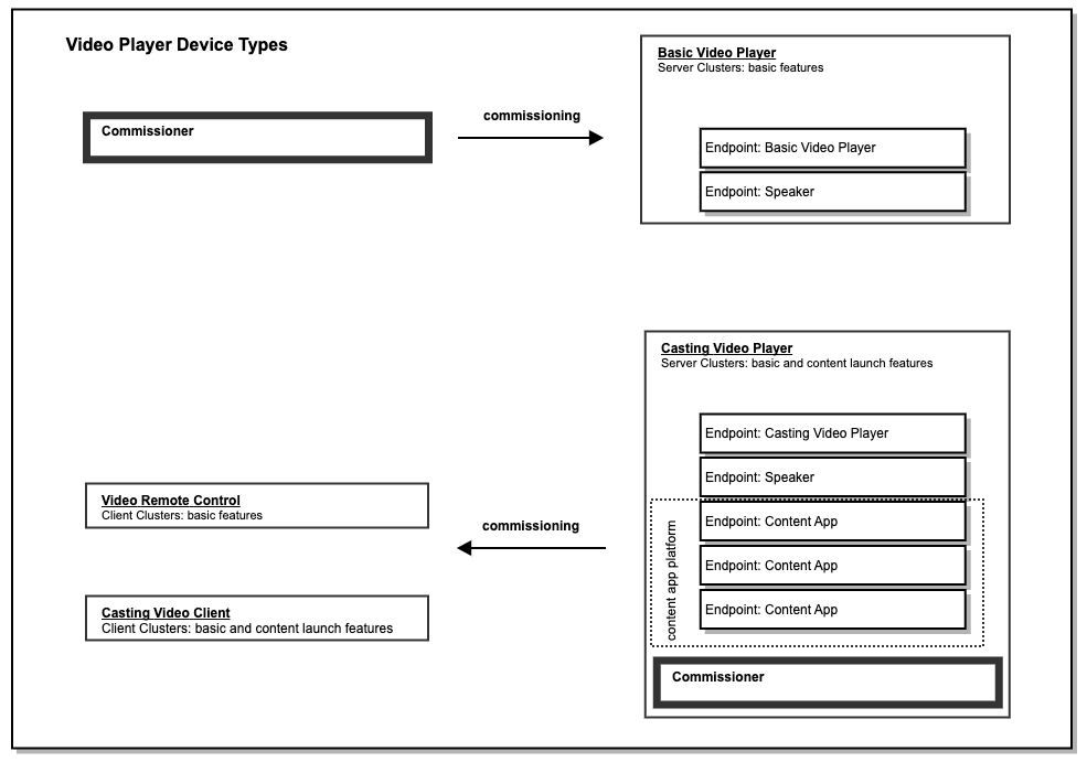
10.1.2. Clients of a Casting Video Player
The clients for a Video Player device can be categorized into 2 high-level groups.
-
Clients controlling the Video Player endpoint such as a remote control (eg : Video Remote device type)
-
Clients controlling specific Content App(s) such as a Phone App casting to a corresponding Content App (eg : Casting Video Client device type)
10.1.3. Endpoint Composition for Content Apps of a Casting Video Player
A Casting Video Player with a Content App Platform SHALL represent each Content App as its own dedicated endpoint where each is identified using the Device ID 0x0024 for "Content App".
The requirements for allocating and deallocating an endpoint address for a Content App SHALL be as described in the System Model specification (see "Dynamic Endpoint allocation").
The following diagram shows a Video Player device containing 3 separate Content Apps:
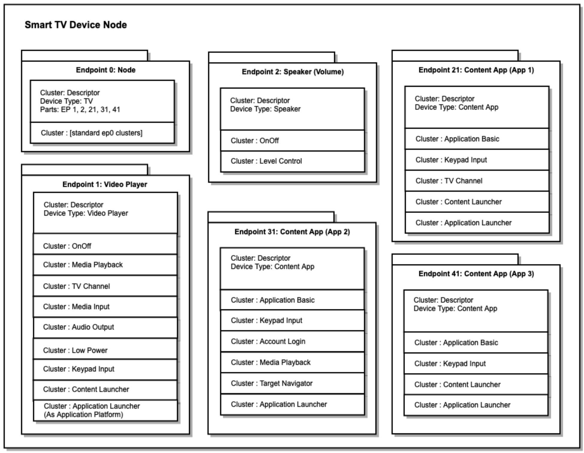
10.1.4. Commissioning
A Basic Video Player SHALL be commissioned like any commissionable node.
A Casting Video Player SHALL be a Commissioner. The primary reason for this requirement is to enable the Casting Video Player to verify, using device attestation, the vendor of a Client for the purpose of controlling content on the Casting Video Player, and to ensure that only clients authorized by a Content App can control it. In this way, a Commissionee associated with a Content App on the Casting Video Player can be commissioned by the Casting Video Player and granted access to the endpoint associated with that Content App.
When a Casting Video Player commissions a Client, such as a Video Remote Control or a Casting Video Client, the Casting Video Player SHALL determine the Content App access for the given Client following the rules defined in this section. Since the Client is being commissioned by the Casting Video Player, the Client, which may be a phone app, SHALL include attestation credentials which are used by the Casting Video Player to determine its Vendor ID.
-
A Casting Video Player SHOULD allow each Content App to specify which clusters it implements, and reflect these clusters in the corresponding endpoint for the given Content App. The method for conveying this information between the Content App and the Casting Video Player is specific to the vendor of the Casting Video Player.
-
A Casting Video Player SHALL allow each Content App to specify values for fields in the Application Basic cluster, such as Vendor ID and Application Name. A Casting Video Player SHALL also use this information to determine access control for Clients commissioned by the Casting Video Player. The method for conveying this information between the Content App and the Casting Video Player is specific to the vendor of the Casting Video Player.
-
A Casting Video Player device SHALL allow each Content App to provide an Allowed Controller Vendor ID list. The Allowed Controller Vendor ID list specifies a list of Vendor IDs for Clients that SHALL be granted access to the endpoint for the given Content App. The Casting Video Player device SHALL use the Allowed Controller Vendor ID list to determine access control for Clients commissioned by the Casting Video Player. Only Clients with a Vendor ID in the Allowed Controller Vendor ID list SHALL be granted access to the given Content App endpoint. The method for conveying this information between the Content App and the Casting Video Player is specific to the vendor of the Casting Video Player. When a Client is commissioned, its attested Vendor ID is used to determine access to Content App endpoints. The Allowed Controller Vendor ID list is contained in the AllowedVendorList attribute of the Application Basic cluster.
A Casting Video Player MAY enable a commissioning flow, which avoids Setup PIN entry by the user, when the following conditions are met: . The Client’s Vendor ID and a Rotating ID (used as a TempAccountIdentifier) are present in its commissionable node advertisement. . The Casting Video Player is able to determine an endpoint corresponding to the given Vendor ID which contains the Account Login cluster (for example, a Content App endpoint). . The Account Login cluster’s GetSetupPIN command returns a SetupPIN which is then used successfully to commission the Client.
A Casting Video Player MAY enable a Content App account login flow, which avoids login name and password entry by the user, when the following conditions are met: . The Client’s Vendor ID and a Rotating ID (used as a TempAccountIdentifier) are present in its commissionable node advertisement. . The Casting Video Player is able to determine an endpoint corresponding to the given Vendor ID which contains the Account Login cluster (for example, a Content App endpoint). . The Account Login cluster’s Login command returns successfully.
In these flows, when the Account Login cluster is located on a Content App endpoint, the Account Login cluster will often be implemented by a different vendor from the Casting Video Player itself. See AccountLoginCluster for further details on the use of these commands.
Since a Client commissioned by the Casting Video Player will only have access to one or more Content App endpoints and the Speaker endpoint (when present), it will not have the ability to access the Application Launcher cluster on the Casting Video Player endpoint. If they do not already exist, the Casting Video Player device SHALL create endpoints for each Content App to which the Client has access and notify the Client of such access by adding an entry for each Content App to the Binding cluster of the Client. The Casting Video Player device SHALL automatically launch the Content App upon commands targeted to a Content App endpoint.
Note: A Client commissioned by the Casting Video Player is able to determine if the corresponding Content App is visible to the user using the Status attribute on the Application Basic cluster for the Content App endpoint. This ensures that the Client cannot access foreground Content App information about any other Content App to which it does not have access. It also ensures that such a client will only need access to specific Content App endpoints and the Speaker endpoint (when present).
10.1.5. Determining Context
A client that controls multiple aspects of the Video Player functionality (like a voice assistant) may have access to multiple endpoints on the Video Player. To determine the current context on the Video Player when the user interacts with the client (for example, when the user interacts with the device using voice), the client can look at the state in the various clusters on the Casting Video Player.
Specifically:
-
Media Input cluster (when CurrentInput does NOT have type INTERNAL, then Video Player is displaying content from a physical input)
-
Application Launcher cluster (CurrentApp indicates the current application endpoint - which may be the Video Player endpoint when no Content App is in the foreground).
-
Target Navigator cluster on current application endpoint (indicates which navigation target the user is in)
The Video Player SHOULD provide a way for the user to view the list of clients with access to control the screen and SHOULD provide a way for the user to revoke this access.
10.1.6. Basic Video Player Features
10.1.6.1. On/Off/Toggle
This feature turns on/off the user-visible power state of the device, corresponding to the on/off/toggle button usually found on a remote or button on the device.
An On/Off cluster on the Video Player endpoint SHALL be used for this feature.
10.1.6.2. Volume Control
This feature controls the speaker volume of the device.
A Speaker endpoint SHALL be used for this feature when the device controls a speaker.
10.1.6.3. Media Playback Control
This feature controls media playback on the device which includes functionality such as Play, Pause, Stop, Rewind, and Fast Forward.
The Media Playback cluster SHALL be used for this functionality.
10.1.6.4. Channel Change
This feature controls channel control functionality on the device which includes functionality such as lineup discovery, change and skip channels.
The Channel cluster SHALL be used for this functionality.
10.1.6.5. Media Input Control
This feature controls the input selection on the device which includes functionality such as input discovery, selection and naming.
The Media Input cluster SHALL be used for this functionality.
10.1.6.6. Audio Output Control
This feature controls audio output selection on the device which includes functionality such as output discovery, selection and naming.
The Audio Output cluster SHALL be used for this functionality.
Note that when the current output is set to an output of type HDMI, adjustments to volume via a Speaker endpoint on the same node MAY cause HDMI volume up/down commands to be sent to the given HDMI output.
10.1.6.7. Sleep/Wake
This feature controls low power mode on the device which includes functionality such as sleep, and declaration of protocols supported for Wakeup.
The Low Power cluster SHALL be used for putting a device into low power (sleep) mode.
The WakeOnLAN cluster SHALL be used for declaring that a device supports the WakeOnLAN protocol.
10.1.6.8. Target Navigation
This feature controls on-screen navigation to custom-named targets, for example, "Settings", "On Demand" and "Search". A list of named targets can be provided for the Video Player endpoint itself, as well as for Content App represented as endpoints.
The Target Navigator cluster SHALL be used for listing navigation targets, invoking navigation to a target, and tracking the current target.
10.1.7. Content Launching Features
Many Video Player devices (traditional TVs, Set Top Boxes, Content Streamers) have advanced features that MAY include any of the following:
-
the ability to search for and playback content such as movies and TV shows
-
a platform for Content Apps that can themselves be launched, and instructed to search and playback content such as movies and TV shows
-
the ability to download and playback basic content referenced by URL
10.1.7.1. Discover and Launch Content App from another Device
This feature allows a client to discover the Content App identification catalogs supported by a Video Player device, and launch an Application based upon a Content App identifier within a given catalog. An example Content App identification catalog is the DIAL registry (http://www.dial-multiscreen.org/).
The Application Launcher cluster SHALL be used for this functionality.
10.1.7.2. Launch Content from another Device
Content search and launch is defined by the Content Launcher cluster which includes feature flags for Content Search and URL Playback which are used to indicate which of these features is supported.
The Content Launcher cluster SHALL be used for this functionality.
10.2. Basic Video Player
This defines conformance to the Basic Video Player device type.
A Video Player (either Basic or Casting) represents a device that is able to play media to a physical output or to a display screen which is part of the device.
A Basic Video Player has playback controls (play, pause, etc.) and keypad remote controls (up, down, number input), but is not able to launch content and is not a content app platform (the Casting Video Player device type is used for these functions).
For example, a Basic Video Player can be a traditional TV device a physical media playback device such as a DVD Player, or a device that provides input to another device like a TV or computer monitor.
Please see Video Player Architecture for additional Basic Video Player requirements relating to Video Player device endpoint composition, commissioning, feature representation in clusters, and UI context.
10.2.1. Revision History
This is the revision history for this device type. The highest revision number in the table below is the revision for this device type.
| Revision | Description |
|---|---|
0 |
Represents device definitions prior to device type revision numbers |
1 |
Initial release of this document |
10.2.2. Classification
| ID | Device Name | Superset | Class | Scope |
|---|---|---|---|---|
0x0028 |
Basic Video Player |
Simple |
Endpoint |
10.2.3. Conditions
This device type SHALL support the following conformance conditions as defined below.
| Feature | Description |
|---|---|
PhysicalInputs |
The device has physical inputs for media. |
Please see the Base Device Type definition for additional conformance tags.
10.2.4. Cluster Requirements
Each endpoint supporting this device type SHALL include these clusters based on the conformance defined below.
| ID | Cluster | Client/Server | Quality | Conformance |
|---|---|---|---|---|
0x0006 |
OnOff |
Server |
M |
|
0x0503 |
WakeOnLAN |
Server |
O |
|
0x0504 |
Channel |
Server |
O |
|
0x0505 |
Target Navigator |
Server |
O |
|
0x0506 |
Media Playback |
Server |
M |
|
0x0507 |
Media Input |
Server |
PhysicalInputs |
|
0x0508 |
Low Power |
Server |
O |
|
0x0509 |
Keypad Input |
Server |
M |
|
0x050B |
Audio Output |
Server |
O |
10.3. Casting Video Player
This defines conformance to the Casting Video Player device type.
A Video Player (either Basic or Casting) represents a device that is able to play media to a physical output or to a display screen which is part of the device.
A Casting Video Player has basic controls for playback (play, pause, etc.) and keypad input (up, down, number input), and is able to launch content.
For example, a Casting Video Player can be a smart TV device, a TV Set Top Box, or a content streaming device that provides input to another device like a TV or computer monitor.
Please see Video Player Architecture for additional Casting Video Player requirements relating to Video Player device endpoint composition, commissioning, feature representation in clusters, and UI context.
10.3.1. Revision History
This is the revision history for this device type. The highest revision number in the table below is the revision for this device type.
| Revision | Description |
|---|---|
0 |
Represents device definitions prior to device type revision numbers |
1 |
Initial release of this document |
10.3.2. Classification
| ID | Device Name | Superset | Class | Scope |
|---|---|---|---|---|
0x0023 |
Casting Video Player |
Simple |
Endpoint |
10.3.3. Conditions
This device type SHALL support the following conformance conditions as defined below.
| Feature | Description |
|---|---|
ContentAppPlatform |
The device includes a Content App Platform. A Content App is usually an application built by a Content Provider. A Casting Video Player with a Content App Platform is able to launch Content Apps and represent these apps as separate endpoints. |
PhysicalInputs |
The device has physical inputs for media. |
Please see the Base Device Type definition for additional conformance tags.
10.3.4. Cluster Requirements
Each endpoint supporting this device type SHALL include these clusters based on the conformance defined below.
| ID | Cluster | Client/Server | Quality | Conformance |
|---|---|---|---|---|
0x0006 |
OnOff |
Server |
M |
|
0x0503 |
WakeOnLAN |
Server |
O |
|
0x0504 |
Channel |
Server |
O |
|
0x0505 |
Target Navigator |
Server |
O |
|
0x0506 |
Media Playback |
Server |
M |
|
0x0507 |
Media Input |
Server |
PhysicalInputs |
|
0x0508 |
Low Power |
Server |
O |
|
0x0509 |
Keypad Input |
Server |
M |
|
0x050A |
Content Launcher |
Server |
M |
|
0x050B |
Audio Output |
Server |
O |
|
0x050C |
Application Launcher |
Server |
ContentAppPlatform |
|
0x050E |
Account Login |
Server |
O |
10.4. Speaker
This defines conformance to the Speaker device type.
This feature controls the speaker volume of the device.
To control unmute/mute, the On/Off cluster SHALL be used. A value of TRUE for the OnOff attribute SHALL represent the volume on (not muted) state, while a value of FALSE SHALL represent the volume off (muted) state. For volume level control, the Level cluster SHALL be used.
A dedicated endpoint is needed because the On/Off cluster can also be used for other purposes, such as for power control.
The decision to use Level and On/Off clusters for volume (rather than defining a new audio control cluster) was made in order to treat volume in a fashion consistent with lighting which also uses these clusters and has matching functional requirements.
10.4.1. Revision History
This is the revision history for this device type. The highest revision number in the table below is the revision for this device type.
| Revision | Description |
|---|---|
0 |
Represents device definitions prior to device type revision numbers |
1 |
Initial release of this document |
10.5. Content App
This defines conformance to the Content App device type.
A Content App is usually an application built by a Content Provider. A Casting Video Player with a Content App Platform is able to launch Content Apps and represent these apps as separate endpoints.
10.5.1. Revision History
This is the revision history for this device type. The highest revision number in the table below is the revision for this device type.
| Revision | Description |
|---|---|
0 |
Represents device definitions prior to device type revision numbers |
1 |
Initial release of this document |
10.5.4. Cluster Requirements
Each endpoint supporting this device type SHALL include these clusters based on the conformance defined below.
| ID | Cluster | Client/Server | Quality | Conformance |
|---|---|---|---|---|
0x0504 |
Channel |
Server |
O |
|
0x0505 |
Target Navigator |
Server |
O |
|
0x0506 |
Media Playback |
Server |
O |
|
0x0509 |
Keypad Input |
Server |
M |
|
0x050A |
Content Launcher |
Server |
O |
|
0x050C |
Application Launcher |
Server |
M |
|
0x050D |
Application Basic |
Server |
M |
|
0x050E |
Account Login |
Server |
O |
10.6. Casting Video Client
This defines conformance to the Casting Video Client device type.
A Casting Video Client is a client that can launch content on a Casting Video Player, for example, a Smart Speaker or a Content Provider phone app.
10.6.1. Revision History
This is the revision history for this device type. The highest revision number in the table below is the revision for this device type.
| Revision | Description |
|---|---|
0 |
Represents device definitions prior to device type revision numbers |
1 |
Initial release of this document |
10.6.2. Classification
| ID | Device Name | Superset | Class | Scope |
|---|---|---|---|---|
0x0029 |
Casting Video Client |
Simple |
Endpoint |
10.6.4. Cluster Requirements
Each endpoint supporting this device type SHALL include these clusters based on the conformance defined below.
| ID | Cluster | Client/Server | Quality | Conformance |
|---|---|---|---|---|
0x0006 |
OnOff |
Client |
M |
|
0x0008 |
Level Control |
Client |
O |
|
0x0503 |
WakeOnLAN |
Client |
O |
|
0x0504 |
Channel |
Client |
O |
|
0x0505 |
Target Navigator |
Client |
O |
|
0x0506 |
Media Playback |
Client |
O |
|
0x0507 |
Media Input |
Client |
O |
|
0x0508 |
Low Power |
Client |
O |
|
0x0509 |
Keypad Input |
Client |
M |
|
0x050A |
Content Launcher |
Client |
M |
|
0x050B |
Audio Output |
Client |
O |
|
0x050C |
Application Launcher |
Client |
O |
|
0x050D |
Application Basic |
Client |
M |
|
0x050E |
Account Login |
Client |
O |
10.7. Video Remote Control
This defines conformance to the Video Remote Control device type.
A Video Remote Control is a client that can control a Video Player, for example, a traditional universal remote control.
10.7.1. Revision History
This is the revision history for this device type. The highest revision number in the table below is the revision for this device type.
| Revision | Description |
|---|---|
0 |
Represents device definitions prior to device type revision numbers |
1 |
Initial release of this document |
10.7.2. Classification
| ID | Device Name | Superset | Class | Scope |
|---|---|---|---|---|
0x002A |
Video Remote Control |
Simple |
Endpoint |
10.7.4. Cluster Requirements
Each endpoint supporting this device type SHALL include these clusters based on the conformance defined below.
| ID | Cluster | Client/Server | Quality | Conformance |
|---|---|---|---|---|
0x0006 |
OnOff |
Client |
M |
|
0x0008 |
Level Control |
Client |
O |
|
0x0503 |
WakeOnLAN |
Client |
O |
|
0x0504 |
Channel |
Client |
O |
|
0x0505 |
Target Navigator |
Client |
O |
|
0x0506 |
Media Playback |
Client |
M |
|
0x0507 |
Media Input |
Client |
O |
|
0x0508 |
Low Power |
Client |
O |
|
0x0509 |
Keypad Input |
Client |
M |
|
0x050A |
Content Launcher |
Client |
O |
|
0x050B |
Audio Output |
Client |
O |
|
0x050C |
Application Launcher |
Client |
O |
|
0x050E |
Account Login |
Client |
O |
11. Generic Device Types
11.1. Mode Select
This defines conformance to the Mode Select device type.
11.1.1. Revision History
This is the revision history for this device type. The highest revision number in the table below is the revision for this device type.
| Revision | Description |
|---|---|
0 |
Represents device definitions prior to device type revision numbers |
1 |
Initial release of this document |
12. Robotic Device Types
12.1. Robotic Vacuum Cleaner Device Type
This defines conformance for the Robotic Vacuum Cleaner device type.
12.1.1. Revision History
This is the revision history for this document.
| Revision | Description |
|---|---|
1 |
Initial release of this document |
12.1.2. Classification
| ID | Device Name | Superset | Class | Scope |
|---|---|---|---|---|
0x0074 |
Robotic Vacuum Cleaner |
Simple |
Endpoint |
12.1.4. Cluster Requirements
Each endpoint supporting this device type SHALL include these clusters based on the conformance defined below.
| ID | Cluster | Client/Server | Quality | Conformance |
|---|---|---|---|---|
0x0003 |
Identify |
Server |
M |
|
0x0054 |
RVC Run Mode |
Server |
M |
|
0x0055 |
RVC Clean Mode |
Server |
O |
|
0x0061 |
RVC Operational State |
Server |
M |
12.1.5. Element Requirements
The table below lists qualities and conformance that override the cluster specification requirements. A blank table cell means there is no change to that item and the value from the cluster specification applies.
| ID | Cluster | Element | Name | Constraint | Access | Conformance |
|---|---|---|---|---|---|---|
0x0054 |
RVC Run Mode |
Feature |
OnOff |
X |
||
0x0055 |
RVC Clean Mode |
Feature |
OnOff |
X |
||
0x0061 |
RVC Operational State |
Command |
Start |
X |
||
0x0061 |
RVC Operational State |
Command |
Stop |
X |
13. Appliances Device Types
13.1. Laundry Washer
A Laundry Washer represents a device that is capable of laundering consumer items. Any laundry washer product may utilize this device type.
A Laundry Washer SHALL be composed of at least one endpoint with the Laundry Washer device type.
13.1.1. Revision History
This is the revision history for this document.
| Revision | Description |
|---|---|
1 |
Initial release |
13.1.4. Cluster Requirements
Each endpoint supporting this device type SHALL include these clusters based on the conformance defined below.
| ID | Cluster | Client/Server | Quality | Conformance |
|---|---|---|---|---|
0x0003 |
Identify |
Server |
O |
|
0x0051 |
Laundry Washer Mode |
Server |
O |
|
0x0006 |
On/Off |
Server |
O |
|
0x0053 |
Laundry Washer Controls |
Server |
O |
|
0x0056 |
Temperature Control |
Server |
O |
|
0x0060 |
Operational State |
Server |
M |
13.1.5. Cluster Restrictions
13.1.5.1. On/Off Cluster (Server) Clarifications
As indicated in the Element Requirements section below, the DF (Dead Front) feature is required for the On/Off cluster in this device type. See the "DeadFrontBehavior feature" section in the On/Off cluster description for detailed requirements. The "dead front" state is linked to the OnOff attribute in the On/Off cluster having the value False. Thus, the Off command of the On/Off cluster SHALL move the device into the "dead front" state, the On command of the On/Off cluster SHALL bring the device out of the "dead front" state, and the device SHALL adhere with the associated requirements on subscription handling and event reporting.
13.1.5.2. Best Effort Attribute Values in "Dead Front" State
When in "dead front", should the operational values of the cluster attributes not be available or accessible, the following are the RECOMMENDED best effort values for per cluster attributes when responding to a new subscription request or a read request. Attributes not listed have no change in their defined or expected values.
| Cluster Name | Attribute | Default |
|---|---|---|
Laundry Washer Mode |
CurrentMode |
MS |
Laundry Washer Controls |
SpinSpeedCurrent |
null |
NumberOfRinses |
null |
|
Temperature Control |
All attributes |
MS |
Operational State |
PhaseList |
null |
CurrentPhase |
null |
|
CountdownTime |
null |
|
OperationalState |
Stopped |
|
OperationalError |
No Error |
13.1.6. Element Requirements
Below list qualities and conformance that override the cluster specification requirements. A blank table cell means there is no change to that item and the value from the cluster specification applies.
| ID | Cluster | Element | Name | Constraint | Access | Conformance |
|---|---|---|---|---|---|---|
0x0006 |
On/Off |
Feature |
DF |
M |
||
0x0051 |
Laundry Washer Mode |
Attribute |
StartUpMode |
X |
||
0x0051 |
Laundry Washer Mode |
Feature |
OnOff |
X |
13.2. Refrigerator
A refrigerator represents a device that contains one or more cabinets that are capable of chilling or freezing food. Examples of consumer products that MAY make use of this device type include refrigerators, freezers, and wine coolers.
13.2.1. Refrigerator Architecture
A Refrigerator is always defined via endpoint composition. See the Section 13.2.5, “Device Type Requirements” section for more details.
A Refrigerator MAY include a semantic tag in the TagList attribute of the Descriptor cluster to describe the primary function of the device, e.g., "Refrigerator" or "Freezer".
An example of a Refrigerator with multiple cabinets is illustrated below.

13.2.2. Revision History
This is the revision history for this document.
| Revision | Description |
|---|---|
1 |
Initial release |
13.2.5. Device Type Requirements
A Refrigerator SHALL be composed of at least one endpoint with the Temperature Controlled Cabinet device type as defined by the conformance below. There MAY be more endpoints with other device types existing in the Refrigerator.
If the Refrigerator contains more than one instance of a Temperature Controlled Cabinet, those instances SHALL include a semantic tag in the TagList attribute of the Descriptor cluster to disambiguate the cabinet, e.g., "freezer" or "refrigerator". Such a semantic tag SHALL be from either the defined Common or Refrigerator namespaces.
| ID | Name | Constraint | Conformance |
|---|---|---|---|
0x0071 |
Temperature Controlled Cabinet |
min 1 |
M |
13.2.6. Cluster Requirements
Each endpoint supporting the refrigerator device type MAY include these clusters based on the conformance defined below.
| ID | Cluster | Client/Server | Quality | Conformance |
|---|---|---|---|---|
0x0003 |
Identify |
Server |
O |
|
0x0052 |
Refrigerator And Temperature Controlled Cabinet Mode |
Server |
O |
|
0x0057 |
Refrigerator Alarm |
Server |
O |
13.2.7. Element Requirements
Below list qualities and conformance that override the cluster specification requirements. A blank table cell means there is no change to that item and the value from the cluster specification applies.
| ID | Cluster | Element | Name | Constraint | Access | Conformance |
|---|---|---|---|---|---|---|
0x0052 |
Refrigerator And Temperature Controlled Cabinet Mode |
Attribute |
StartUpMode |
X |
||
0x0052 |
Refrigerator And Temperature Controlled Cabinet Mode |
Feature |
OnOff |
X |
13.3. Room Air Conditioner
This defines conformance to the Room Air Conditioner device type.
A Room Air Conditioner is a device with the primary function of controlling the air temperature in a single room.
13.3.1. Room Air Conditioner Architecture
A Room Air Conditioner is a device which at a minimum is capable of being turned on and off and of controlling the temperature in the living space.
A Room Air Conditioner MAY also support additional capabilities via endpoint composition. See the Section 13.3.5, “Device Type Requirements” section for typical device types.
The following diagram shows an example Room Air Conditioner consisting of a parent endpoint that is the Room Air Conditioner device type and several child endpoints providing additional capabilities. Note that two of the child endpoints are of the same device type, Temperature Sensor, which are being disambiguated via the requirements of endpoint composition defined in the system model.

13.3.2. Revision History
This is the revision history for this document.
| Revision | Description |
|---|---|
1 |
Initial Release |
13.3.3. Classification
| ID | Device Name | Superset | Class | Scope |
|---|---|---|---|---|
0x0072 |
Room Air Conditioner |
Simple |
Endpoint |
13.3.5. Device Type Requirements
A Room Air Conditioner MAY have zero or more of each device type listed in this table subject to the conformance column of the table. All devices used in compositions SHALL adhere to the disambiguation requirements of the System Model. Additional device types not listed in this table MAY also be included in device compositions.
| ID | Name | Constraint | Conformance |
|---|---|---|---|
0x0302 |
Temperature Sensor |
O |
|
0x0307 |
Humidity Sensor |
O |
13.3.6. Cluster Requirements
Each endpoint supporting this device type SHALL include these clusters based on the conformance defined below.
| ID | Cluster | Client/Server | Conformance |
|---|---|---|---|
0x0003 |
Identify |
Server |
M |
0x0004 |
Groups |
Server |
O |
0x0005 |
Scenes |
Server |
P, O |
0x0006 |
On/Off |
Server |
M |
0x0201 |
Thermostat |
Server |
M |
0x0202 |
Fan Control |
Server |
O |
0x0402 |
Temperature Measurement |
Server |
O |
0x0405 |
Relative Humidity Measurement |
Server |
O |
13.3.7. Cluster Restrictions
13.3.7.1. On/Off Cluster (Server) Clarifications
As indicated in the Element Requirements section below, the DF (Dead Front) feature is required for the On/Off cluster in this device type. See the "DeadFrontBehavior feature" section in the On/Off cluster description for detailed requirements. The "dead front" state is linked to the OnOff attribute in the On/Off cluster having the value False. Thus, the Off command of the On/Off cluster SHALL move the device into the "dead front" state, the On command of the On/Off cluster SHALL bring the device out of the "dead front" state, and the device SHALL adhere with the associated requirements on subscription handling and event reporting.
13.3.7.2. Best Effort Attribute Values in "Dead Front" State
When in "dead front", should the operational values of the cluster attributes not be available or accessible, the following are the RECOMMENDED best effort values for per cluster attributes when responding to a new subscription request or a read request. Attributes not listed have no change in their defined or expected values.
| Cluster Name | Attribute | Default |
|---|---|---|
Thermostat |
LocalTemperature |
null |
Temperature Measurement |
MeasuredValue |
null |
Relative Humidity Measurement |
MeasuredValue |
null |
Fan Control |
SpeedSetting |
null |
PercentSetting |
null |
13.3.8. Element Requirements
This lists qualities and conformance that override the cluster specification requirements. A blank table cell means there is no change to that item and the value from the cluster specification applies.
| ID | Cluster | Element | Name | Constraint | Access | Conformance |
|---|---|---|---|---|---|---|
0x0006 |
On/Off |
Feature |
DF |
M |
13.4. Temperature Controlled Cabinet
A Temperature Controlled Cabinet only exists composed as part of another device type. It represents a single cabinet chilling or freezing food in a refrigerator, freezer, wine chiller or other similar device.
13.4.1. Revision History
This is the revision history for this document.
| Revision | Description |
|---|---|
1 |
Initial release |
13.4.2. Classification
| ID | Device Name | Superset | Class | Scope |
|---|---|---|---|---|
0x0071 |
Temperature Controlled Cabinet |
Simple |
Endpoint |
13.4.4. Cluster Requirements
Each endpoint supporting this device type SHALL include these clusters based on the conformance defined below.
| ID | Cluster | Client/Server | Quality | Conformance |
|---|---|---|---|---|
0x0056 |
Temperature Control |
Server |
M |
|
0x0402 |
Temperature Measurement |
Server |
O |
|
0x0052 |
Refrigerator And Temperature Controlled Cabinet Mode |
Server |
O |
13.4.5. Element Requirements
Below list qualities and conformance that override the cluster specification requirements. A blank table cell means there is no change to that item and the value from the cluster specification applies.
| ID | Cluster | Element | Name | Constraint | Access | Conformance |
|---|---|---|---|---|---|---|
0x0052 |
Refrigerator And Temperature Controlled Cabinet Mode |
Attribute |
StartUpMode |
X |
||
0x0052 |
Refrigerator And Temperature Controlled Cabinet Mode |
Feature |
OnOff |
X |
13.5. Dishwasher
A dishwasher is a device that is generally installed in residential homes and is capable of washing dishes, cutlery, and other items associate with food preparation and consumption. The device can be permanently installed or portable and can have variety of filling and draining methods.
13.5.1. Revision History
This is the revision history for this document.
| Revision | Description |
|---|---|
1 |
Initial Release |
13.5.4. Cluster Requirements
Each endpoint supporting this device type SHALL include these clusters based on the conformance defined below.
| ID | Cluster | Client/Server | Conformance |
|---|---|---|---|
0x0003 |
Identify |
Server |
O |
0x0006 |
On/Off |
Server |
O |
0x0056 |
Temperature Control |
Server |
O |
0x0059 |
Dishwasher Mode |
Server |
O |
0x005D |
Dishwasher Alarm |
Server |
O |
0x0060 |
Operational State |
Server |
M |
Notes
-
A dishwasher cycle is a combination of a mode (if supported) and a temperature (if supported). The operational state cluster is then used to start the cycle once these selections have been made via the client.
13.5.5. Cluster Restrictions
13.5.5.1. On/Off Cluster (Server) Clarifications
As indicated in the Element Requirements section below, the DF (Dead Front) feature is required for the On/Off cluster in this device type. See the "DeadFrontBehavior feature" section in the On/Off cluster description for detailed requirements. The "dead front" state is linked to the OnOff attribute in the On/Off cluster having the value False. Thus, the Off command of the On/Off cluster SHALL move the device into the "dead front" state, the On command of the On/Off cluster SHALL bring the device out of the "dead front" state, and the device SHALL adhere with the associated requirements on subscription handling and event reporting.
13.5.5.2. Best Effort Attribute Values in "Dead Front" State
When in "dead front", should the operational values of the cluster attributes not be available or accessible, the following are the RECOMMENDED best effort values for per cluster attributes when responding to a new subscription request or a read request. Attributes not listed have no change in their defined or expected values.
| Cluster Name | Attribute | Default |
|---|---|---|
Dishwasher Mode |
CurrentMode |
MS |
Temperature Control |
All attributes |
MS |
Dishwasher Operational State |
PhaseList |
null |
CurrentPhase |
null |
|
CountdownTime |
null |
|
OperationalState |
Stopped |
|
OperationalError |
No Error |
13.5.6. Element Requirements
This lists qualities and conformance that override the cluster specification requirements. A blank table cell means there is no change to that item and the value from the cluster specification applies.
| ID | Cluster | Element | Name | Constraint | Access | Conformance |
|---|---|---|---|---|---|---|
0x0006 |
On/Off |
Feature |
DF |
M |
||
0x0059 |
Dishwasher Mode |
Attribute |
StartUpMode |
X |
||
0x0059 |
Dishwasher Mode |
Feature |
OnOff |
X |