Notice
of
Use
Copyright
Notice,
License
and
Disclosure
Disclaimer
Copyright
©
Connectivity
Standards
Alliance
(2021).
(2021-2023).
All
rights
reserved.
This
The
information
within
this
document
is
the
property
of
the
Connectivity
Standards
Alliance
and
its
use
and
disclosure
are
restricted.
restricted,
except
as
expressly
set
forth
herein.
Elements
Connectivity
Standards
Alliance
hereby
grants
you
a
fully-paid,
non-exclusive,
nontransferable,
worldwide,
limited
and
revocable
license
(without
the
right
to
sublicense),
under
Connectivity
Standards
Alliance’s
applicable
copyright
rights,
to
view,
download,
save,
reproduce
and
use
the
document
solely
for
your
own
internal
purposes
and
in
accordance
with
the
terms
of
the
license
set
forth
herein.
This
license
does
not
authorize
you
to,
and
you
expressly
warrant
that
you
shall
not:
(a)
permit
others
(outside
your
organization)
to
use
this
document;
(b)
post
or
publish
this
document;
(c)
modify,
adapt,
translate,
or
otherwise
change
this
document
in
any
manner
or
create
any
derivative
work
based
on
this
document;
(d)
remove
or
modify
any
notice
or
label
on
this
document,
including
this
Copyright
Notice,
License
and
Disclaimer.
The
Connectivity
Standards
Alliance
specifications
does
not
grant
you
any
license
hereunder
other
than
as
expressly
stated
herein.
Elements
of
this
document
may
be
subject
to
third
party
intellectual
property
rights,
including
without
limitation,
patent,
copyright
or
trademark
rights
(such
a
rights,
and
any
such
third
party
may
or
may
not
be
a
member
of
the
Connectivity
Standards
Alliance).
Alliance.
Connectivity
Standards
Alliance
members
grant
other
Connectivity
Standards
Alliance
members
certain
intellectual
property
rights
as
set
forth
in
the
Connectivity
Standards
Alliance
IPR
Policy.
Connectivity
Standards
Alliance
members
do
not
grant
you
any
rights
under
this
license.
The
Connectivity
Standards
Alliance
is
not
responsible
for,
and
shall
not
be
held
responsible
in
any
manner
for
for,
identifying
or
failing
to
identify
any
or
all
such
third
party
intellectual
property
rights.
Please
visit
www.csa-iot.org
for
more
information
on
how
to
become
a
member
of
the
Connectivity
Standards
Alliance.
This
document
and
the
information
contained
herein
are
provided
on
an
"AS
IS"
“AS
IS”
basis
and
the
Connectivity
Standards
Alliance
DISCLAIMS
ALL
WARRANTIES
EXPRESS
OR
IMPLIED,
INCLUDING
BUT
NOT
LIMITED
TO
(A)
ANY
WARRANTY
THAT
THE
USE
OF
THE
INFORMATION
HEREIN
WILL
NOT
INFRINGE
ANY
RIGHTS
OF
THIRD
PARTIES
(INCLUDING
WITHOUT
LIMITATION
ANY
INTELLECTUAL
PROPERTY
RIGHTS
INCLUDING
PATENT,
COPYRIGHT
OR
TRADEMARK
RIGHTS)
RIGHTS);
OR
(B)
ANY
IMPLIED
WARRANTIES
OF
MERCHANTABILITY,
FITNESS
FOR
A
PARTICULAR
PURPOSE,
TITLE
OR
NON-INFRINGEMENT.
NONINFRINGEMENT.
IN
NO
EVENT
WILL
THE
CONNECTIVITY
STANDARDS
ALLIANCE
BE
LIABLE
FOR
ANY
LOSS
OF
PROFITS,
LOSS
OF
BUSINESS,
LOSS
OF
USE
OF
DATA,
INTERRUPTION
OF
BUSINESS,
OR
FOR
ANY
OTHER
DIRECT,
INDIRECT,
SPECIAL
OR
EXEMPLARY,
INCIDENTAL,
PUNITIVE
OR
CONSEQUENTIAL
DAMAGES
OF
ANY
KIND,
IN
CONTRACT
OR
IN
TORT,
IN
CONNECTION
WITH
THIS
DOCUMENT
OR
THE
INFORMATION
CONTAINED
HEREIN,
EVEN
IF
ADVISED
OF
THE
POSSIBILITY
OF
SUCH
LOSS
OR
DAMAGE.
All company, brand and product names in this document may be trademarks that are the sole property of their respective owners.
This
legal
notice
and
disclaimer
must
be
included
on
all
copies
of
this
document
that
are
made.
document.
Connectivity
Standards
Alliance
508
Second
Street,
Suite
206
Davis,
CA
95616,
USA
Revision History
| Revision | Date | Details | Editor |
|---|---|---|---|
01 | September 23, 2022 | Version 1.0 | Robert Szewczyk |
02 | May 17, 2023 | Version 1.1 | Robert Szewczyk |
Introduction
The Matter Application Cluster specification defines generic interfaces that are sufficiently general to be of use across a wide range of application domains.
Scope and Purpose
This document specifies the Matter Application Cluster Library (MACL). The MACL is a repository for cluster functionality that is developed by the Connectivity Standards Alliance, and is a working library with regular updates as new functionality is added. A developer constructing a new application should use the MACL to find relevant cluster functionality that can be incorporated into the new application. Correspondingly, new clusters that are defined for applications should be considered for inclusion in the MACL.
The MACL consists of a number of sets of clusters. Clusters that are generally useful across many application domains are included in the General set. Clusters that are intended for use mainly in specific application domains are grouped together in domain oriented sets.
References
The following standards and specifications contain provisions, which through reference in this document constitute provisions of this specification. All the standards and specifications listed are normative references. At the time of publication, the editions indicated were valid. All standards and specifications are subject to revision, and parties to agreements based on this specification are encouraged to investigate the possibility of applying the most recent editions of the standards and specifications indicated below.
CSA Reference Documents
| Reference | Reference Location/URL | Description |
|---|---|---|
|
https://github.com/CHIP-Specifications/connectedhomeip-spec/raw/build-sample/pdf/main.pdf |
Matter Core Specification - Under development |
|
|
https://github.com/CHIP-Specifications/connectedhomeip-spec/raw/build-sample/pdf/device_library.pdf |
Matter Device Library Specification - Under development |
|
|
Organizational Processes and Procedures, 13-0625, revision 8, November 2021 |
External Reference Documents
| Reference | Reference Location/URL | Description |
|---|---|---|
|
http://www.dial-multiscreen.org/dial-registry/namespace-database |
DIAL Registry |
|
|
https://hdmiforum.org/hdmi-forum-releases-version-2-1-hdmi-specification/ |
HDMI CEC specification |
|
|
Wake on LAN Magic Packet specification |
Provisional
Per [CSA-PNP] , when a specification is completed there may be sections of specification text (or smaller pieces of a section) that are not certifiable at this stage. These sections (or smaller pieces of a section) are marked as provisional prior to publishing the specification. This specification uses well-defined notation to mark Provisional Conformance (see [MatterCore] , Section 7.3) or notes a section of text with the term "provisional".
List of Provisional Items
The following is a list of provisional items:
-
Support for Scenes cluster is provisional.
-
Support for Pulse Width Modulation cluster and for the Frequency feature of the Level control cluster is provisional
-
Support for Ballast Configuration Cluster is provisional.
-
Support for Fan Control cluster is provisional.
1. General
The Cluster Library is made of individual chapters such as this one. See Document Control in the Cluster Library for a list of all chapters and documents. References between chapters are made using a X.Y notation where X is the chapter and Y is the sub-section within that chapter. References to external documents are contained in Chapter 1 and are made using [ Rn ] notation.
1.1. General Description
1.1.1. Introduction
The clusters specified in this document are generic interfaces that are sufficiently general to be of use across a wide range of application domains.
1.1.2. Cluster List
This section lists the general clusters as specified in this chapter.
| ID | Cluster Name | Description |
|---|---|---|
|
0x0003 |
Attributes and commands for putting a device into Identification mode (e.g., flashing a light) |
|
|
0x0004 |
Cluster to manage the associated endpoint’s membership into one or more groups to support groupcast interactions. |
|
|
0x0005 |
Attributes and commands for setting up and recalling a number of scenes for a device. Each scene corresponds to a set of stored values of specified device attributes. |
|
|
0x0006 |
Attributes and commands for switching devices between ‘On’ and ‘Off’ states. |
|
|
0x0008 |
Attributes and commands for controlling a characteristic of devices that can be set to a level between fully ‘On’ and fully ‘Off’. |
|
|
0x0045 |
Attribute and event for a boolean state variable |
|
|
0x0050 |
Allows a user to choose one mode option from several predefined values |
|
|
0x0508 |
This cluster provides an interface for managing low power mode on a device. |
|
|
0x0503 |
This cluster provides an interface for managing low power mode on a device that supports the Wake On LAN protocol. |
|
|
0x003b |
Attributes and events for various types of switch devices. |
1.2. Identify
This cluster supports an endpoint identification state (e.g., flashing a light), that indicates to an observer (e.g., an installer) which of several nodes and/or endpoints it is. It also supports a multicast request that any endpoint that is identifying itself to respond to the initiator.
The state of this cluster MAY be shared on more than one endpoint on a node.
1.2.1. Revision History
The global ClusterRevision attribute value SHALL be the highest revision number in the table below.
| Rev | Description |
|---|---|
|
1 |
global mandatory ClusterRevision attribute added |
|
2 |
CCB 2808 |
|
3 |
All Hubs changes |
|
4 |
new data model format and notation |
1.2.4. Features
This cluster SHALL support the Feature Map global attribute with these bits defined:
| Bit | Code | Name | Description |
|---|---|---|---|
|
0 |
QRY |
Query |
Multicast query for identification state |
1.2.5. Attributes
| ID | Name | Type | Constraint | Quality | Default | Access | Conformance |
|---|---|---|---|---|---|---|---|
|
0x0000 |
IdentifyTime |
uint16 |
all |
0 |
RW VO |
M |
|
|
0x0001 |
IdentifyType |
enum8 |
desc |
0 |
R V |
M * |
* IdentifyType represents a mandatory attribute that was previously not present or optional. Implementers should be aware that older devices may not implement it.
1.2.5.1. IdentifyTime Attribute
This attribute specifies the remaining length of time, in seconds, that the endpoint will continue to identify itself.
If this attribute is set to a value other than 0 then the device SHALL enter its identification state, in order to indicate to an observer which of several nodes and/or endpoints it is. It is RECOMMENDED that this state consists of flashing a light with a period of 0.5 seconds. The IdentifyTime attribute SHALL be decremented every second while in this state.
If this attribute reaches or is set to the value 0 then the device SHALL terminate its identification state.
1.2.5.2. IdentifyType Attribute
This attribute specifies how the identification state is presented to the user.
This field SHALL contain one of the values listed below:
| Value | Presentation | Notes |
|---|---|---|
|
0x00 |
None |
No presentation. |
|
0x01 |
Light output |
Light output of a lighting product. |
|
0x02 |
Visible indicator |
Typically a small LED. |
|
0x03 |
Audible beep |
|
|
0x04 |
Display |
Presentation will be visible on display screen. |
|
0x05 |
Actuator |
Presentation will be conveyed by actuator functionality such as through a window blind operation or in-wall relay. |
1.2.6. Commands
| ID | Name | Direction | Response | Access | Conformance |
|---|---|---|---|---|---|
|
0x00 |
Identify |
client ⇒ server |
Y |
M |
M |
|
0x01 |
IdentifyQuery |
client ⇒ server |
IdentifyQueryResponse |
M |
QRY |
|
0x40 |
TriggerEffect |
client ⇒ server |
Y |
M |
O |
|
0x00 |
IdentifyQueryResponse |
server ⇒ client |
N |
QRY |
1.2.6.1. Identify Command
This command starts or stops the receiving device identifying itself.
This command SHALL have the following data fields:
| ID | Name | Type | Constraint | Quality | Default | Conformance |
|---|---|---|---|---|---|---|
|
0 |
IdentifyTime |
uint16 |
all |
M |
1.2.6.1.1. Effect on Receipt
On receipt of this command, the device SHALL set the IdentifyTime attribute to the value of the IdentifyTime field. This then starts, continues, or stops the device’s identification state as detailed in IdentifyTime Attribute .
1.2.6.2. IdentifyQuery Command
This command allows the sending device to request the target or targets to respond if they are currently identifying themselves.
This command has no data fields.
1.2.6.2.1. Effect on Receipt
On receipt of this command, if the IdentifyTime attribute is not zero, then it SHALL generate a response in the form of an IdentifyQueryResponse command, see IdentifyQueryResponse Command . Otherwise it SHALL take no further action.
1.2.6.3. TriggerEffect Command
This command allows the support of feedback to the user, such as a certain light effect. It is used to allow an implementation to provide visual feedback to the user under certain circumstances such as a color light turning green when it has successfully connected to a network. The use of this command and the effects themselves are entirely up to the implementer to use whenever a visual feedback is useful but it is not the same as and does not replace the identify mechanism used during commissioning.
The TriggerEffect command SHALL have the following data fields:
| ID | Name | Type | Constraint | Quality | Default | Conformance |
|---|---|---|---|---|---|---|
|
0 |
EffectIdentifier |
enum8 |
desc |
M |
||
|
1 |
EffectVariant |
enum8 |
desc |
M |
1.2.6.3.1. EffectIdentifier Field
This field specifies the identify effect to use. All values of the EffectIdentifier SHALL be supported. Implementors MAY deviate from the example light effects in the table below, but they SHOULD indicate during testing how they handle each effect.
This field SHALL contain one of the non-reserved values listed below.
| Value | Effect | Notes |
|---|---|---|
|
0x00 |
Blink |
e.g., Light is turned on/off once. |
|
0x01 |
Breathe |
e.g., Light is turned on/off over 1 second and repeated 15 times. |
|
0x02 |
Okay |
e.g., Colored light turns green for 1 second; non-colored light flashes twice. |
|
0x0b |
Channel change |
e.g., Colored light turns orange for 8 seconds; non-colored light switches to the maximum brightness for 0.5s and then minimum brightness for 7.5s. |
|
0xfe |
Finish effect |
Complete the current effect sequence before terminating. e.g., if in the middle of a breathe effect (as above), first complete the current 1s breathe effect and then terminate the effect. |
|
0xff |
Stop effect |
Terminate the effect as soon as possible. |
1.2.6.3.2. EffectVariant Field
This field is used to indicate which variant of the effect, indicated in the EffectIdentifier field, SHOULD be triggered. If a device does not support the given variant, it SHALL use the default variant. This field SHALL contain one of the values listed below:
| Value | Description |
|---|---|
|
0x00 |
Default |
1.2.6.4. IdentifyQueryResponse Command
This command is generated in response to receiving an IdentifyQuery command, see IdentifyQuery Command , in the case that the device is currently identifying itself.
This command SHALL have the following data fields:
| ID | Name | Type | Constraint | Quality | Default | Conformance |
|---|---|---|---|---|---|---|
|
0 |
Timeout |
uint16 |
all |
M |
1.2.6.4.1. Timeout Field
This field contains the current value of the IdentifyTime attribute, and specifies the length of time, in seconds, that the device will continue to identify itself.
1.2.6.4.2. Effect on Receipt
On receipt of this command, the device is informed of a device in the network which is currently identifying itself. This information MAY be particularly beneficial in situations where there is no commissioning tool. Note that there MAY be multiple responses in case the IdentifyQuery command was sent as a groupcast or multicast, even from a single node in case multiple endpoints on that node are currently identifying themselves.
1.3. Groups
The Groups cluster manages, per endpoint, the content of the node-wide Group Table that is part of the underlying interaction layer.
In a network supporting fabrics, group IDs referenced by attributes or other elements of this cluster are scoped to the accessing fabric.
The Groups cluster is scoped to the endpoint. Groups cluster commands support discovering the endpoint membership in a group, adding the endpoint to a group, removing the endpoint from a group, removing endpoint membership from all groups. All commands defined in this cluster SHALL only affect groups scoped to the accessing fabric.
When group names are supported, the server stores a name string, which is set by the client for each assigned group and indicated in response to a client request.
Note that configuration of group addresses for outgoing commands is achieved using the Message Layer mechanisms where the Group Table is not involved. Hence this cluster does not play a part in that.
1.3.1. Revision History
The global ClusterRevision attribute value SHALL be the highest revision number in the table below.
| Rev | Description |
|---|---|
|
1 |
global mandatory ClusterRevision attribute added; CCB 1745 2100 |
|
2 |
CCB 2289 |
|
3 |
CCB 2310 2704 |
|
4 |
new data model format and notation |
1.3.4. Features
This cluster SHALL support the FeatureMap global attribute:
| Bit | Code | Name | Def | Description |
|---|---|---|---|---|
|
0 |
GN |
Group Names |
0 |
The ability to store a name for a group. |
The following sections describe each feature in some detail. Further details are found within the specification.
1.3.5. Dependencies
For correct operation of the AddGroupIfIdentifying command, any endpoint that supports the Groups server cluster SHALL also support the Identify server cluster.
1.3.6. Attributes
The attribute IDs for the Groups cluster are listed in the table below.
| ID | Name | Type | Constraint | Quality | Default | Access | Conformance |
|---|---|---|---|---|---|---|---|
|
0x0000 |
NameSupport |
map8 |
desc |
F |
0 |
R V |
M |
1.3.6.1. NameSupport Attribute
This attribute provides legacy, read-only access to whether the Group Names feature is supported. The most significant bit, bit 7, SHALL be equal to bit 0 of the FeatureMap attribute. All other bits SHALL be 0.
| Bit | Code | Name | Def | Description |
|---|---|---|---|---|
|
7 |
GN |
Group Names |
0 |
The ability to store a name for a group. |
1.3.7. Commands
The command IDs for the Groups cluster are listed in the table below.
| ID | Name | Direction | Response | Access | Conformance |
|---|---|---|---|---|---|
|
0x00 |
AddGroup |
client ⇒ server |
AddGroupResponse |
F M |
M |
|
0x01 |
ViewGroup |
client ⇒ server |
ViewGroupResponse |
F O |
M |
|
0x02 |
GetGroupMembership |
client ⇒ server |
GetGroupMembershipResponse |
F O |
M |
|
0x03 |
RemoveGroup |
client ⇒ server |
RemoveGroupResponse |
F M |
M |
|
0x04 |
RemoveAllGroups |
client ⇒ server |
Y |
F M |
M |
|
0x05 |
AddGroupIfIdentifying |
client ⇒ server |
Y |
F M |
M |
|
0x00 |
AddGroupResponse |
server ⇒ client |
N |
M |
|
|
0x01 |
ViewGroupResponse |
server ⇒ client |
N |
M |
|
|
0x02 |
GetGroupMembershipResponse |
server ⇒ client |
N |
M |
|
|
0x03 |
RemoveGroupResponse |
server ⇒ client |
N |
M |
1.3.7.1. AddGroup Command
The AddGroup command allows a client to add group membership in a particular group for the server endpoint.
The AddGroup command SHALL have the following data fields:
| Id | Name | Type | Constraint | Quality | Default | Conformance |
|---|---|---|---|---|---|---|
|
0 |
GroupID |
group-id |
1 to max |
M |
||
|
1 |
GroupName |
string |
max 16 |
M |
1.3.7.1.1. When Generated
The GroupID field SHALL be used to identify the group and any associated key material to which the server endpoint is to be added. The GroupName field MAY be set to a human-readable name for the group. If the client has no name for the group, the GroupName field SHALL be set to the empty string.
1.3.7.1.2. Effect on Receipt
If the server does not support group names, the GroupName field SHALL be ignored.
On receipt of the AddGroup command, the server SHALL perform the following procedure:
-
If the command fields are not within constraints, the status SHALL be CONSTRAINT_ERROR, and the server continues from step 6.
-
If the receiving node requires security material to support the group ID and that material does not exist for this group ID, the status SHALL be UNSUPPORTED_ACCESS and the server continues from step 6.
-
If the server endpoint is a member of the group indicated by the GroupID, the group name SHALL be updated (if supported) to GroupName, the status SHALL be SUCCESS, and the server continues from step 6.
-
If there are no available resources to add the membership for the server endpoint, the status SHALL be RESOURCE_EXHAUSTED, and the server continues from step 6.
-
The server SHALL add the server endpoint as a member of the group indicated by the GroupID, the group name SHALL be updated (if supported) to GroupName, and the status SHALL be SUCCESS.
-
If the GroupID had already been added to the Group Table because of a previous AddGroup or AddGroupIfIdentifying command and a GroupName is provided and the server supports GroupName storage, then the GroupName associated with the GroupID in the Group Table SHALL be updated to reflect the new GroupName provided for the Group, such that subsequent ViewGroup commands yield the same name for all endpoints which have a group association to the given GroupID.
-
-
If the AddGroup command was received as a unicast, the server SHALL generate an AddGroupResponse command with the Status field set to the evaluated status. If the AddGroup command was received as a groupcast, the server SHALL NOT generate an AddGroupResponse command.
See AddGroupResponse Command for a description of the AddGroupResponse command.
1.3.7.2. ViewGroup Command
The ViewGroup command allows a client to request that the server responds with a ViewGroupResponse command containing the name string for a particular group.
The ViewGroup command SHALL have the following data fields:
| Id | Name | Type | Constraint | Quality | Default | Conformance |
|---|---|---|---|---|---|---|
|
0 |
GroupID |
group-id |
1 to max |
M |
1.3.7.2.1. Effect on Receipt
On receipt of the ViewGroup command, the server SHALL perform the following procedure:
-
If the command fields are not within constraints, the status SHALL be CONSTRAINT_ERROR and the server continues from step 4.
-
If the server endpoint is a member of the group indicated by the GroupID, the status SHALL be SUCCESS, and the server continues from step 4.
-
Else the status SHALL be NOT_FOUND.
-
If the ViewGroup command was received as a unicast, the server SHALL generate a ViewGroupResponse command for the group, and the Status field set to the evaluated status. If the ViewGroup command was received as a groupcast, the server SHALL NOT generate a ViewGroupResponse command.
See ViewGroupResponse Command for a description of the ViewGroupResponse command.
1.3.7.3. GetGroupMembership Command
The GetGroupMembership command allows a client to inquire about the group membership of the server endpoint, in a number of ways.
The GetGroupMembership command SHALL have the following data fields:
| Id | Name | Type | Constraint | Quality | Default | Conformance |
|---|---|---|---|---|---|---|
|
0 |
GroupList |
list[group-id] |
all[1 to max] |
M |
1.3.7.3.1. Effect on Receipt
On receipt of the GetGroupMembership command, the server SHALL respond with group membership information using the GetGroupMembershipResponse command as follows:
If the GroupList field is empty, the server SHALL respond with all group IDs indicating the groups of which the server endpoint is a member.
If the GroupList field contains at least one group ID indicating a group of which the server endpoint is a member, the server SHALL respond with each group ID indicating a group of which the server endpoint is a member that matches a group in the GroupList field.
If the GroupList field contains one or more group IDs but does not contain any group ID indicating a group of which the server endpoint is a member, the server SHALL only respond if the command is unicast. The response SHALL return with an empty GroupList field.
1.3.7.4. RemoveGroup Command
The RemoveGroup command allows a client to request that the server removes the membership for the server endpoint, if any, in a particular group.
The RemoveGroup command SHALL have the following data fields:
| Id | Name | Type | Constraint | Quality | Default | Conformance |
|---|---|---|---|---|---|---|
|
0 |
GroupID |
group-id |
1 to max |
M |
1.3.7.4.1. Effect on Receipt
On receipt of the RemoveGroup command, the server SHALL perform the following procedure:
-
If the command fields are not within constraints, the status SHALL be CONSTRAINT_ERROR and the server continues from step 4.
-
If the server endpoint is a member of the group indicated by the GroupID, the server SHALL remove the server endpoint membership in the group, the status SHALL be SUCCESS, and the server continues from step 4.
-
Else the status SHALL be NOT_FOUND.
-
If the RemoveGroup command was received as a unicast, the server SHALL generate a RemoveGroupResponse command with the Status field set to the evaluated status. If the RemoveGroup command was received as a groupcast, the server SHALL NOT generate a RemoveGroupResponse command.
See RemoveGroupResponse Command for a description of the RemoveGroupResponse command.
Additionally, if the Scenes cluster is supported on the same endpoint, scenes associated with the indicated group SHALL be removed on that endpoint.
1.3.7.5. RemoveAllGroups Command
The RemoveAllGroups command allows a client to direct the server to remove all group associations for the server endpoint.
The RemoveAllGroups command has no data fields.
1.3.7.5.1. Effect on Receipt
On receipt of this command, the server SHALL remove all group memberships for the server endpoint from the Group Table. If the RemoveAllGroups command was received as unicast and a response is not suppressed, the server SHALL generate a response with the Status field set to SUCCESS.
Additionally, if the Scenes cluster is supported on the same endpoint, all scenes, except for scenes associated with group ID 0, SHALL be removed on that endpoint.
1.3.7.6. AddGroupIfIdentifying Command
The AddGroupIfIdentifying command allows a client to add group membership in a particular group for the server endpoint, on condition that the endpoint is identifying itself. Identifying functionality is controlled using the Identify cluster, (see Identify ).
This command might be used to assist configuring group membership in the absence of a commissioning tool.
The AddGroupIfIdentifying command SHALL have the following data fields:
| Id | Name | Type | Constraint | Quality | Default | Conformance |
|---|---|---|---|---|---|---|
|
0 |
GroupID |
group-id |
1 to max |
M |
||
|
1 |
GroupName |
string |
max 16 |
M |
1.3.7.6.1. When Generated
The GroupID field SHALL be used to identify the group and any associated key material to which the server endpoint is to be added. The GroupName field MAY be set to a human-readable name for the group. If the client has no name for the group, the GroupName field SHALL be set to the empty string.
1.3.7.6.2. Effect on Receipt
If the server does not support group names, the GroupName field SHALL be ignored.
On receipt of the AddGroupIfIdentifying command, the server SHALL perform the following procedure:
-
The server verifies that it is currently identifying itself. If the server it not currently identifying itself, the status SHALL be SUCCESS, and the server continues from step 7.
-
If the command fields are not within constraints, the status SHALL be CONSTRAINT_ERROR and the server continues from step 7.
-
If the receiving node requires security material to support the group ID, and that material does not exist for this group ID, the status SHALL be UNSUPPORTED_ACCESS and the server continues from step 7.
-
If the server endpoint is a member of the group indicated by the GroupID, the status SHALL be SUCCESS and the server continues from step 7.
-
If there are no available resources to add the membership for the server endpoint, the status SHALL be RESOURCE_EXHAUSTED and the server continues from step 7.
-
The server SHALL add the server endpoint as a member of the group indicated by the GroupID, the group name SHALL be updated (if supported) to GroupName, and the status SHALL be SUCCESS.
-
If the GroupID had already been added to the Group Table because of a previous AddGroup or AddGroupIfIdentifying command and a GroupName is provided and the server supports GroupName storage, then the GroupName associated with the GroupID in the Group Table SHALL be updated to reflect the new GroupName provided for the Group, such that subsequent ViewGroup commands yield the same name for all endpoints which have a group association to the given GroupID.
-
-
If the AddGroupIfIdentifying command was received as unicast and the evaluated status is not SUCCESS, or if the AddGroupIfIdentifying command was received as unicast and the evaluated status is SUCCESS and a response is not suppressed, the server SHALL generate a response with the Status field set to the evaluated status.
1.3.7.7. AddGroupResponse Command
The AddGroupResponse is sent by the Groups cluster server in response to an AddGroup command.
The AddGroupResponse command SHALL have the following data fields:
| Id | Name | Type | Constraint | Quality | Default | Conformance |
|---|---|---|---|---|---|---|
|
0 |
Status |
enum8 |
desc |
M |
||
|
1 |
GroupID |
group-id |
1 to max |
M |
1.3.7.8. ViewGroupResponse Command
The ViewGroupResponse command is sent by the Groups cluster server in response to a ViewGroup command.
The ViewGroupResponse command SHALL have the following data fields:
| Id | Name | Type | Constraint | Quality | Default | Conformance |
|---|---|---|---|---|---|---|
|
0 |
Status |
enum8 |
desc |
M |
||
|
1 |
GroupID |
group-id |
1 to max |
M |
||
|
2 |
GroupName |
string |
max 16 |
M |
1.3.7.8.1. When Generated
This command is generated in response to a received ViewGroup command. The Status field is according to the Effect on Receipt section of the ViewGroup command. The GroupID field is set to the GroupID field of the received ViewGroup command. If the status is SUCCESS, and group names are supported, the GroupName field is set to the group name associated with that group in the Group Table; otherwise it is set to the empty string.
1.3.7.9. GetGroupMembershipResponse Command
The GetGroupMembershipResponse command is sent by the Groups cluster server in response to a GetGroupMembership command.
The GetGroupMembershipResponse command SHALL have the following data fields:
| Id | Name | Type | Constraint | Quality | Default | Conformance |
|---|---|---|---|---|---|---|
|
0 |
Capacity |
uint8 |
all |
X |
M |
|
|
1 |
GroupList |
list[group-id] |
all[1 to max] |
M |
The fields of the GetGroupMembershipResponse command have the following semantics:
The Capacity field SHALL contain the remaining capacity of the Group Table of the node. The following values apply:
-
0 - No further groups MAY be added.
-
0 < Capacity < 0xfe - Capacity holds the number of groups that MAY be added.
-
0xfe - At least 1 further group MAY be added (exact number is unknown).
-
null - It is unknown if any further groups MAY be added.
The
GroupList
field
SHALL
contain
either
the
group
IDs
of
all
the
groups
in
the
Group
Table
for
which
the
server
endpoint
is
a
member
of
the
group
(in
the
case
where
the
GroupList
field
of
the
received
GetGroupMembership
command
was
empty),
or
the
group
IDs
of
all
the
groups
in
the
Group
Table
for
which
the
server
endpoint
is
a
member
of
the
group
and
for
which
the
group
ID
was
included
in
the
the
GroupList
field
of
the
received
GetGroupMembership
command
(in
the
case
where
the
GroupList
field
of
the
received
GetGroupMembership
command
was
not
empty).
Zigbee:
If
the
total
number
of
groups
will
cause
the
maximum
payload
length
of
a
frame
to
be
exceeded,
then
the
GroupList
field
SHALL
contain
only
as
many
groups
as
will
fit.
1.3.7.9.1. When Generated
See GetGroupMembership Command Effect on Receipt .
1.3.7.10. RemoveGroupResponse Command
The RemoveGroupResponse command is generated by the server in response to the receipt of a RemoveGroup command.
The RemoveGroupResponse command SHALL have the following data fields:
| Id | Name | Type | Constraint | Quality | Default | Conformance |
|---|---|---|---|---|---|---|
|
0 |
Status |
enum8 |
desc |
M |
||
|
1 |
GroupID |
group-id |
1 to max |
M |
1.4. Scenes
The Scenes cluster provides attributes and commands for setting up and recalling scenes. Each scene corresponds to a set of stored values of specified attributes for one or more clusters on the same end point as the Scenes cluster.
In most cases scenes are associated with a particular group identifier. Scenes MAY also exist without a group, in which case the value 0 replaces the group identifier. Note that extra care is required in these cases to avoid a scene identifier collision, and that commands related to scenes without a group MAY only be unicast, i.e., they MAY not be multicast or broadcast.
In a network supporting fabrics, scenes are scoped to the accessing fabric. When storing scene information, implementations need to take care of this.
|
Note
|
Support for Scenes cluster is provisional. |
1.4.1. Revision History
The global ClusterRevision attribute value SHALL be the highest revision number in the table below.
| Rev | Description |
|---|---|
|
1 |
global mandatory ClusterRevision attribute added; CCB 1745 |
|
2 |
TransitionTime field added to the RecallScene command |
|
3 |
CCB 2427 3026 |
|
4 |
new data model format and notation |
1.4.2. Classification
| Hierarchy | Role | PICS Code | Primary Transaction |
|---|---|---|---|
|
Base |
Application |
S |
Type 1 (client to server) |
1.4.4. Features
This cluster SHALL support the FeatureMap global attribute:
| Bit | Code | Name | Def | Description |
|---|---|---|---|---|
|
0 |
SN |
Scene Names |
0 |
The ability to store a name for a scene. |
The following sections describe each feature in some detail. Further details are found within the specification.
1.4.5. Dependencies
Any endpoint that implements the Scenes server cluster SHALL also implement the Groups server cluster.
Note that the RemoveGroup command and the RemoveAllGroups command of the Groups cluster also remove scenes.
1.4.6. Data Types
1.4.6.1. AttributeValuePair
This data type indicates a combination of an identifier and the value of an attribute.
| ID | Name | Type | Constraint | Quality | Access | Default | Conformance |
|---|---|---|---|---|---|---|---|
|
0 |
AttributeID |
attribute-id |
all |
RW |
Matter
|
||
|
1 |
AttributeValue |
variable |
RW |
M |
1.4.6.1.1. AttributeID
This field SHALL be present or not present, for all instances in the Scenes cluster. If this field is not present, then the data type of AttributeValue SHALL be determined by the order and data type defined in the cluster specification. Otherwise the data type of AttributeValue SHALL be the data type of the attribute indicated by AttributeID.
1.4.6.2. ExtensionFieldSet
This data type indicates for a given cluster a set of attributes and their values. Only attributes which have the "S" designation in the Quality column of the cluster specification SHALL be used in the AttributeValueList field.
| ID | Name | Type | Constraint | Quality | Access | Default | Conformance |
|---|---|---|---|---|---|---|---|
|
0 |
ClusterID |
cluster-id |
all |
RW |
M |
||
|
1 |
AttributeValueList |
list[AttributeValuePair] |
RW |
M |
1.4.7. Attributes
The attribute IDs for the Scene cluster are listed in the table below.
| ID | Name | Type | Constraint | Quality | Default | Access | Conformance |
|---|---|---|---|---|---|---|---|
|
0x0000 |
SceneCount |
uint8 |
all |
0 |
R V |
M |
|
|
0x0001 |
CurrentScene |
uint8 |
all |
0 |
R V |
M |
|
|
0x0002 |
CurrentGroup |
group-id |
all |
0 |
R V |
M |
|
|
0x0003 |
SceneValid |
bool |
all |
FALSE |
R V |
M |
|
|
0x0004 |
NameSupport |
map8 |
desc |
0 |
R V |
M |
|
|
0x0005 |
LastConfiguredBy |
node-id |
- |
X |
null |
R V |
O |
1.4.7.1. SceneCount Attribute
The SceneCount attribute specifies the number of scenes currently in the server’s Scene Table.
1.4.7.2. CurrentScene Attribute
The CurrentScene attribute holds the scene identifier of the scene last invoked.
1.4.7.3. CurrentGroup Attribute
The CurrentGroup attribute holds the group identifier of the scene last invoked, or 0 if the scene last invoked is not associated with a group.
1.4.7.4. SceneValid Attribute
The SceneValid attribute indicates whether the state of the server corresponds to that associated with the CurrentScene and CurrentGroup attributes. TRUE indicates that these attributes are valid, FALSE indicates that they are not valid.
Before a scene has been stored or recalled, this attribute is set to FALSE. After a successful StoreScene or RecallScene command it is set to TRUE. If, after a scene is stored or recalled, the state of the server is modified, this attribute is set to FALSE.
1.4.7.5. NameSupport Attribute
This attribute provides legacy, read-only access to whether the Scene Names feature is supported. The most significant bit, bit 7, SHALL be equal to bit 0 of the FeatureMap attribute. All other bits SHALL be 0.
| Bit | Code | Name | Def | Description |
|---|---|---|---|---|
|
7 |
SN |
Scene Names |
0 |
The ability to store a name for a scene. |
1.4.7.6. LastConfiguredBy Attribute
The LastConfiguredBy attribute holds the Node ID (the IEEE address in case of Zigbee) of the node that last configured the Scene Table.
The null value indicates that the server has not been configured, or that the identifier of the node that last configured the Scenes cluster is not known.
1.4.8. Scene Table
The Scene Table is used to store information for each scene capable of being invoked on the server. Each scene is defined for a particular group.
The fields of each Scene Table entry consist of a number of sets. The base set consists of the first four fields of Fields of a Scene Table Entry . A set of extension fields can be added by each additional cluster implemented on the same endpoint.
| Name | Type | Constraint | Description |
|---|---|---|---|
|
SceneGroupID |
group-id |
all |
The group identifier for which this scene applies, or 0 if the scene is not associated with a group. |
|
SceneID |
uint8 |
all |
The identifier, unique within this group, which is used to identify this scene. |
|
SceneName |
string |
0 to 16 bytes |
The name of the scene (optional) |
|
SceneTransitionTime |
uint16 |
all |
The amount of time, in seconds, it will take for a cluster to change from its current state to the requested state. |
|
ExtensionFieldSets |
Variable |
Variable |
See the Scene Table Extensions subsections of individual clusters. A Scene Table Extension SHALL only use attributes marked with "S" in the Quality column of the cluster definition. Each extension field set holds a set of values of these attributes for a cluster implemented on the same endpoint. The sum of all such sets defines a scene. |
|
TransitionTime100ms |
uint8 |
0 to 9 |
Together with the SceneTransitionTime field, this field allows the transition time to be specified in tenths of a second. |
1.4.8.1. Scene Names
Scene
names
are
between
0
and
16
bytes
long.
Support
of
scene
names
is
optional,
and
is
indicated
by
the
NameSupport
attribute.
If
scene
names
are
not
supported,
any
commands
that
write
a
scene
name
SHALL
simply
discard
the
name,
and
any
command
that
returns
a
scene
names
SHALL
return
an
empty
string.
Zigbee:
Note
older
implementations
may
return
the
null
string.
1.4.9. Commands
The command IDs for the Scenes cluster are listed in the table below.
| ID | Name | Direction | Response | Access | Conformance |
|---|---|---|---|---|---|
|
0x00 |
AddScene |
client ⇒ server |
AddSceneResponse |
M |
M |
|
0x01 |
ViewScene |
client ⇒ server |
ViewSceneResponse |
O |
M |
|
0x02 |
RemoveScene |
client ⇒ server |
RemoveSceneResponse |
M |
M |
|
0x03 |
RemoveAllScenes |
client ⇒ server |
RemoveAllScenesResponse |
M |
M |
|
0x04 |
StoreScene |
client ⇒ server |
StoreSceneResponse |
M |
M |
|
0x05 |
RecallScene |
client ⇒ server |
Y |
O |
M |
|
0x06 |
GetSceneMembership |
client ⇒ server |
GetSceneMembershipResponse |
O |
M |
|
0x40 |
EnhancedAddScene |
client ⇒ server |
EnhancedAddSceneResponse |
M |
O |
|
0x41 |
EnhancedViewScene |
client ⇒ server |
EnhancedViewSceneResponse |
O |
O |
|
0x42 |
CopyScene |
client ⇒ server |
CopySceneResponse |
M |
O |
|
0x00 |
AddSceneResponse |
server ⇒ client |
N |
M |
|
|
0x01 |
ViewSceneResponse |
server ⇒ client |
N |
M |
|
|
0x02 |
RemoveSceneResponse |
server ⇒ client |
N |
M |
|
|
0x03 |
RemoveAllScenesResponse |
server ⇒ client |
N |
M |
|
|
0x04 |
StoreSceneResponse |
server ⇒ client |
N |
M |
|
|
0x06 |
GetSceneMembershipResponse |
server ⇒ client |
N |
M |
|
|
0x40 |
EnhancedAddSceneResponse |
server ⇒ client |
N |
O |
|
|
0x41 |
EnhancedViewSceneResponse |
server ⇒ client |
N |
O |
|
|
0x42 |
CopySceneResponse |
server ⇒ client |
N |
O |
1.4.9.1. Generic Usage Notes
Scene identifier 0, along with group identifier 0, is reserved for the global scene used by the On/Off cluster.
On receipt of the AddScene command, the SceneTransitionTime field of the Scene Table SHALL be updated with the value of the TransitionTime field and the TransitionTime100ms field SHALL be set to zero.
1.4.9.2. AddScene Command
The AddScene command SHALL have the following data fields:
| Id | Name | Type | Constraint | Quality | Default | Conformance |
|---|---|---|---|---|---|---|
|
0 |
GroupID |
group-id |
all |
M |
||
|
1 |
SceneID |
uint8 |
all |
M |
||
|
2 |
TransitionTime |
uint16 |
all |
M |
||
|
3 |
SceneName |
string |
max 16 |
M |
||
|
4 |
ExtensionFieldSets |
list[ExtensionFieldSet] |
M |
It is not mandatory for an extension field set to be included in the command for every cluster on that endpoint that has a defined extension field set. Extension field sets MAY be omitted, including the case of no extension field sets at all.
1.4.9.2.1. Effect on Receipt
On receipt of the AddScene command, the server SHALL perform the following procedure:
-
If the value of the GroupID field is non-zero, the server verifies that the endpoint has an entry for that GroupID in the Group Table. If there is no such entry in the Group Table, the status SHALL be ILLEGAL_COMMAND and the server continues from step 4.
-
The server verifies that it has free entries in its Scene Table. If the server has no further free entries in its Scene Table, the status SHALL be RESOURCE_EXHAUSTED and the server continues from step 4.
-
The server adds the scene entry into its Scene Table with fields copied from the AddScene command data fields and the status SHALL be SUCCESS. If there is already a scene in the Scene Table with the same scene identifier and group identifier, it SHALL overwrite it.
-
If the AddScene command was received as a unicast, the server SHALL then generate an AddSceneResponse command with the Status field set to the evaluated status. If the AddScene command was received as a groupcast, the server SHALL NOT generate an AddSceneResponse command.
See AddSceneResponse Command for a description of the AddSceneResponse command.
1.4.9.3. ViewScene Command
The ViewScene command SHALL have the following data fields:
| Id | Name | Type | Constraint | Quality | Default | Conformance |
|---|---|---|---|---|---|---|
|
0 |
GroupID |
group-id |
all |
M |
||
|
1 |
SceneID |
uint8 |
all |
M |
1.4.9.3.1. Effect on Receipt
On receipt of the ViewScene command, the server SHALL perform the following procedure:
-
If the value of the GroupID field is non-zero, the server verifies that the endpoint has an entry for that GroupID in the Group Table. If there is no such entry in the Group Table, the status SHALL be ILLEGAL_COMMAND and the server continues from step 4.
-
The server verifies that the scene entry corresponding to the GroupID and SceneID fields exists in its Scene Table. If there is no such entry in its Scene Table, the status SHALL be NOT_FOUND and the server continues from step 4.
-
The server retrieves the requested scene entry from its Scene Table and the status SHALL be SUCCESS.
-
If the ViewScene command was received as a unicast, the server SHALL then generate a ViewSceneResponse command with the retrieved scene entry and the Status field set to the evaluated status. If the ViewScene command was received as a groupcast, the server SHALL NOT generate a ViewSceneResponse command.
See ViewSceneResponse Command for a description of the ViewSceneResponse command.
1.4.9.4. RemoveScene Command
The RemoveScene command SHALL have the following data fields:
| Id | Name | Type | Constraint | Quality | Default | Conformance |
|---|---|---|---|---|---|---|
|
0 |
GroupID |
group-id |
all |
M |
||
|
1 |
SceneID |
uint8 |
all |
M |
1.4.9.4.1. Effect on Receipt
On receipt of the RemoveScene command, the server SHALL perform the following procedure:
-
If the value of the GroupID field is non-zero, the server verifies that the endpoint has an entry for that GroupID in the Group Table. If there is no such entry in the Group Table, the status SHALL be ILLEGAL_COMMAND and the server continues from step 4.
-
The server verifies that the scene entry corresponding to the GroupID and SceneID fields exists in its Scene Table. If there is no such entry in its Scene Table, the status SHALL be NOT_FOUND and the server continues from step 4.
-
The server removes the requested scene entry from its Scene Table and the status SHALL be SUCCESS.
-
If the RemoveScene command was received as a unicast, the server SHALL then generate a RemoveSceneResponse command with the Status field set to the evaluated status. If the RemoveScene command was received as a groupcast, the server SHALL NOT generate a RemoveSceneResponse command.
See RemoveSceneResponse Command for a description of the RemoveSceneResponse command.
1.4.9.5. RemoveAllScenes Command
The RemoveAllScenes command SHALL have the following data fields:
| Id | Name | Type | Constraint | Quality | Default | Conformance |
|---|---|---|---|---|---|---|
|
0 |
GroupID |
group-id |
all |
M |
1.4.9.5.1. Effect on Receipt
On receipt of the RemoveAllScenes command, the server SHALL perform the following procedure:
-
If the value of the GroupID field is non-zero, the server verifies that the endpoint has an entry for that GroupID in the Group Table. If there is no such entry in the Group Table, the status SHALL be ILLEGAL_COMMAND and the server continues from step 3.
-
The server SHALL remove all scenes, corresponding to the value of the GroupID field, from its Scene Table and the status SHALL be SUCCESS.
-
If the RemoveAllScenes command was received as a unicast, the server SHALL then generate a RemoveAllScenesResponse command with the Status field set to the evaluated status. If the RemoveAllScenes command was received as a groupcast, the server SHALL NOT generate a RemoveAllScenesResponse command.
See RemoveAllScenesResponse Command for a description of the RemoveAllScenesResponse command.
1.4.9.6. StoreScene Command
The StoreScene command SHALL have the following data fields:
| Id | Name | Type | Constraint | Quality | Default | Conformance |
|---|---|---|---|---|---|---|
|
0 |
GroupID |
group-id |
all |
M |
||
|
1 |
SceneID |
uint8 |
all |
M |
1.4.9.6.1. Effect on Receipt
On receipt of the StoreScene command, the server SHALL perform the following procedure:
-
If the value of the GroupID field is non-zero, the server verifies that the endpoint has an entry for that GroupID in the Group Table. If there is no such entry in the Group Table, the status SHALL be ILLEGAL_COMMAND and the server continues from step 4.
-
The server verifies that it has free entries in its Scene Table. If the server has no further free entries in its Scene Table, the status SHALL be RESOURCE_EXHAUSTED and the server continues from step 4.
-
The server adds the scene entry into its Scene Table along with all extension field sets corresponding to the current state of other clusters on the same endpoint and with the SceneTransitionTime and SceneName fields set to 0 and the empty string, respectively. If there is already a scene in the Scene Table with the same SceneID and GroupID, it SHALL overwrite it, i.e., it SHALL first remove all information included in the original scene entry except for the SceneTransitionTime and SceneName fields, which are left unaltered. The status SHALL be SUCCESS.
-
If the StoreScene command was received as a unicast, the server SHALL then generate a StoreSceneResponse command with the Status field set to the evaluated status. If the StoreScene command was received as a groupcast, the server SHALL NOT generate a StoreSceneResponse command.
Note that if a scene to be stored requires a TransitionTime field and/or a SceneName field, these must be set up by a prior AddScene command, e.g., with no scene extension field sets.
See StoreSceneResponse Command for a description of the StoreSceneResponse command.
1.4.9.7. RecallScene Command
The RecallScene command SHALL have the following data fields:
| Id | Name | Type | Constraint | Quality | Default | Conformance |
|---|---|---|---|---|---|---|
|
0 |
GroupID |
group-id |
all |
M |
||
|
1 |
SceneID |
uint8 |
all |
M |
||
|
2 |
TransitionTime |
uint16 |
all |
X |
O |
1.4.9.7.1. Effect on Receipt
On receipt of the RecallScene command, the server SHALL perform the following procedure:
-
If the value of the GroupID field is non-zero, the server verifies that the endpoint has an entry for that GroupID in the Group Table. If there is no such entry in the Group Table, the status SHALL be ILLEGAL_COMMAND and the server continues from step 4.
-
The server verifies that the scene entry corresponding to the GroupID and SceneID fields exists in its Scene Table. If there is no such entry in its Scene Table, the status SHALL be NOT_FOUND and the server continues from step 4.
-
The server retrieves the requested scene entry from its Scene Table. For each other cluster implemented on the endpoint, it SHALL retrieve any corresponding extension fields from the Scene Table and set the attributes and corresponding state of the cluster accordingly. If there is no extension field set for a cluster, the state of that cluster SHALL remain unchanged. If an extension field set omits the values of any trailing attributes, the values of these attributes SHALL remain unchanged.
-
The server SHALL then generate a response with the Status field set to the evaluated status.
If the TransitionTime data field is present in the command and its value is not equal to null, this field SHALL indicate the transition time in 1/10ths of a second. In all other cases (command data field not present or value equal to null), the SceneTransitionTime field of the Scene Table entry SHALL indicate the transition time. The transition time determines how long the transition takes from the old cluster state to the new cluster state. It is recommended that, where possible (e.g., it is not possible for attributes with Boolean data type), a gradual transition SHOULD take place from the old to the new state over this time. However, the exact transition is manufacturer dependent.
1.4.9.8. GetSceneMembership Command
The GetSceneMembership command can be used to find an unused scene identifier within a certain group when no commissioning tool is in the network, or for a commissioning tool to get the used scene identifiers within a certain group, for the endpoint that implements this cluster.
The GetSceneMembership command SHALL have the following data fields:
| Id | Name | Type | Constraint | Quality | Default | Conformance |
|---|---|---|---|---|---|---|
|
0 |
GroupID |
group-id |
all |
M |
1.4.9.8.1. Effect on Receipt
On receipt of the GetSceneMembership command, the server SHALL perform the following procedure:
-
If the value of the GroupID field is non-zero, the server verifies that the endpoint has an entry for that GroupID in the Group Table. If there is no such entry in the Group Table, the status SHALL be ILLEGAL_COMMAND and the server continues from step 2.
-
If the GetSceneMembership command was received as a unicast, the server SHALL then generate a GetSceneMembershipResponse command with the Status field set to the evaluated status. If the GetSceneMembership command was not received as a unicast, the server SHALL only generate a GetSceneMembershipResponse command with the Status field set to the evaluated status if an entry within the Scene Table corresponds to the GroupID.
See GetSceneMembershipResponse Command for a description of the GetSceneMembershipResponse command.
1.4.9.9. EnhancedAddScene Command
The EnhancedAddScene command allows a scene to be added using a finer scene transition time than the AddScene command.
This command SHALL have the same data fields as the AddScene command, with the following difference:
The TransitionTime data field SHALL be measured in tenths of a second rather than in seconds.
1.4.9.9.1. Effect on Receipt
On receipt of the EnhancedAddScene command, the server SHALL perform the following procedure:
-
If the value of the GroupID field is non-zero, the server verifies that the endpoint has an entry for that GroupID in the Group Table. If there is no such entry in the Group Table, the status SHALL be ILLEGAL_COMMAND and the server continues from step 4.
-
The server verifies that it has free entries in its Scene Table. If the server has no further free entries in its Scene Table, the status SHALL be RESOURCE_EXHAUSTED and the server continues from step 4.
-
The server adds the scene entry into its Scene Table with fields copied from the EnhancedAddScene command data fields and the status SHALL be SUCCESS. If there is already a scene in the Scene Table with the same SceneID and GroupID, it SHALL overwrite it, i.e., it SHALL first remove all information included in the original scene entry. The TransitionTime field (measured in tenths of a second) SHALL be separated into whole seconds for the SceneTransitionTime field and tenths of a second for the TransitionTime100ms field of the Scene Table entry, as specified.
-
If the EnhancedAddScene command was received as a unicast, the server SHALL then generate an EnhancedAddSceneResponse command with the Status field set to the evaluated status. If the EnhancedAddScene command was received as a groupcast, the server SHALL NOT generate an EnhancedAddSceneResponse command.
See EnhancedAddSceneResponse Command for a description of the EnhancedAddSceneResponse command.
1.4.9.10. EnhancedViewScene Command
The EnhancedViewScene command allows a scene to be retrieved using a finer scene transition time than the ViewScene command.
This command SHALL have the same data fields as the ViewScene command.
1.4.9.10.1. Effect on Receipt
On receipt of the EnhancedViewScene command, the server SHALL perform the following procedure:
-
If the value of the GroupID field is non-zero, the server verifies that the endpoint has an entry for that GroupID in the Group Table. If there is no such entry in the Group Table, the status SHALL be ILLEGAL_COMMAND and the server continues from step 4.
-
The server verifies that the scene entry corresponding to the GroupID and SceneID fields exists in its Scene Table. If there is no such entry in its Scene Table, the status SHALL be NOT_FOUND and the server continues from step 4.
-
The server retrieves the requested scene entry from its Scene Table and the status SHALL be SUCCESS.
-
If the EnhancedViewScene command was received as a unicast, the server SHALL then generate an EnhancedViewSceneResponse command with the Status field set to the evaluated status. If the EnhancedViewScene command was received as a groupcast, the server SHALL NOT generate an EnhancedViewSceneResponse command.
See EnhancedViewSceneResponse Command for a description of the EnhancedViewSceneResponse command.
1.4.9.11. CopyScene Command
The CopyScene command allows a client to efficiently copy scenes from one group/scene identifier pair to another group/scene identifier pair.
The CopyScene command SHALL have the following data fields:
| Id | Name | Type | Constraint | Quality | Default | Conformance |
|---|---|---|---|---|---|---|
|
0 |
Mode |
map8 |
desc |
M |
||
|
1 |
GroupIdentifierFrom |
group-id |
all |
M |
||
|
2 |
SceneIdentifierFrom |
uint8 |
all |
M |
||
|
3 |
GroupIdentifierTo |
group-id |
all |
M |
||
|
4 |
SceneIdentifierTo |
uint8 |
all |
M |
1.4.9.11.1. Mode Field
The Mode field contains information of how the scene copy is to proceed. This field SHALL be formatted as illustrated in Format of the Mode Field of the CopyScene Command .
| Bit | Description |
|---|---|
|
0 |
CopyAllScenes |
|
1-7 |
(Reserved) |
The CopyAllScenes subfield is 1-bit in length and indicates whether all scenes are to be copied. If this value is set to 1, all scenes are to be copied and the SceneIdentifierFrom and SceneIdentifierTo fields SHALL be ignored. Otherwise this field is set to 0.
1.4.9.11.2. GroupIdentifierFrom Field
The GroupIdentifierFrom field specifies the identifier of the group from which the scene is to be copied. Together with the SceneIdentifierFrom field, this field uniquely identifies the scene to copy from the Scene Table.
1.4.9.11.3. SceneIdentifierFrom Field
The SceneIdentifierFrom field specifies the identifier of the scene from which the scene is to be copied. Together with the GroupIdentifierFrom field, this field uniquely identifies the scene to copy from the Scene Table.
1.4.9.11.4. GroupIdentifierTo Field
The GroupIdentifierTo field specifies the identifier of the group to which the scene is to be copied. Together with the SceneIdentifierTo field, this field uniquely identifies the scene to copy to the Scene Table.
1.4.9.11.5. SceneIdentifierTo Field
The SceneIdentifierTo field specifies the identifier of the scene to which the scene is to be copied. Together with the GroupIdentifierTo field, this field uniquely identifies the scene to copy to the Scene Table.
1.4.9.11.6. Effect on Receipt
On receipt of the CopyScene command, the server SHALL perform the following procedure:
-
If the value of either the GroupIdentifierFrom field or the Group Identifier To field is non-zero, the server verifies that the endpoint has an entry for these non-zero group identifiers in the Group Table. If there are no such entries in the Group Table, the status SHALL be ILLEGAL_COMMAND and the server continues from step 5.
-
The server verifies that the scene entry corresponding to the Group Identifier From and SceneIdentifierFrom fields exists in its Scene Table. If there is no such entry in its Scene Table, the status SHALL be NOT_FOUND and the server continues from step 5.
-
If the CopyAllScenes sub-field of the Mode field is set to 1 or the scene entry corresponding to the GroupIdentifierTo and SceneIdentifierTo fields does not exist in the Scene Table and if the server has no further free entries in its Scene Table, the status SHALL be RESOURCE_EXHAUSTED and the server continues from step 5.
-
The status SHALL be SUCCESS. If the CopyAllScenes sub-field of the Mode field is set to 1, the server SHALL copy all its available scenes with group identifier equal to the GroupIdentifierFrom field under the group identifier specified in the GroupIdentifierTo field, leaving the scene identifiers the same. In this case, the SceneIdentifierFrom and SceneIdentifierTo fields are ignored. If the CopyAllScenes sub-field of the Mode field is set to 0, the server SHALL copy the Scene Table entry corresponding to the GroupIdentifierFrom and SceneIdentifierFrom fields to the Scene Table entry corresponding to the GroupIdentifierTo and SceneIdentifierTo fields. If a scene already exists under the same group/scene identifier pair, it SHALL be overwritten.
-
If the CopyScene command was received as a unicast, the server SHALL then generate a CopySceneResponse command with the Status field set to the evaluated status. If the CopyScene command was received as a groupcast, the server SHALL NOT generate an CopySceneResponse command.
See CopySceneResponse Command for a description of the CopySceneResponse command.
1.4.9.12. AddSceneResponse Command
The AddSceneResponse command SHALL have the following data fields:
| Id | Name | Type | Constraint | Quality | Default | Conformance |
|---|---|---|---|---|---|---|
|
0 |
Status |
enum8 |
desc |
M |
||
|
1 |
GroupID |
group-id |
all |
M |
||
|
2 |
SceneID |
uint8 |
all |
M |
1.4.9.12.1. When Generated
This command is generated in response to a received AddScene command, see AddScene Command . The Status field is set according to the Effect on Receipt section for AddScene. The GroupID and SceneID fields are set to the corresponding fields of the received AddScene command.
1.4.9.13. ViewSceneResponse Command
The ViewSceneResponse command SHALL have the following data fields:
| Id | Name | Type | Constraint | Quality | Default | Conformance |
|---|---|---|---|---|---|---|
|
0 |
Status |
enum8 |
desc |
M |
||
|
1 |
GroupID |
group-id |
all |
M |
||
|
2 |
SceneID |
uint8 |
all |
M |
||
|
3 |
TransitionTime |
uint16 |
all |
desc |
||
|
4 |
SceneName |
string |
max 16 |
desc |
||
|
5 |
ExtensionFieldSets |
list[ExtensionFieldSet] |
desc |
1.4.9.13.1. When Generated
This command is generated in response to a received ViewScene command, see ViewScene Command .
The entry in the Scene Table with SceneID and GroupID given in the received ViewScene command is located (if possible). The Status field is set according to the Effect on Receipt section for ViewScene. The GroupID and SceneID fields are set to the corresponding fields in the received ViewScene command.
If the status is SUCCESS, the TransitionTime, SceneName and ExtensionFieldSets fields are copied from the corresponding fields in the Scene Table entry, otherwise they are omitted.
1.4.9.14. RemoveSceneResponse Command
The RemoveSceneResponse command SHALL have the following data fields:
| Id | Name | Type | Constraint | Quality | Default | Conformance |
|---|---|---|---|---|---|---|
|
0 |
Status |
enum8 |
desc |
M |
||
|
1 |
GroupID |
group-id |
all |
M |
||
|
2 |
SceneID |
uint8 |
all |
M |
1.4.9.14.1. When Generated
This command is generated in response to a received RemoveScene command, see RemoveScene Command . The Status field is set according to the Effect on Receipt section for RemoveScene. The GroupID and SceneID fields are set to the corresponding fields of the received RemoveScene command.
1.4.9.15. RemoveAllScenesResponse Command
The RemoveAllScenesResponse command SHALL have the following data fields:
| Id | Name | Type | Constraint | Quality | Default | Conformance |
|---|---|---|---|---|---|---|
|
0 |
Status |
enum8 |
desc |
M |
||
|
1 |
GroupID |
group-id |
all |
M |
1.4.9.15.1. When Generated
This command is generated in response to a received RemoveAllScenes command, see RemoveAllScenes Command . The Status field is according to the Effect on Receipt section for RemoveAllScenes. The GroupID field is set to the corresponding field of the received RemoveAllScenes command.
1.4.9.16. StoreSceneResponse Command
The StoreSceneResponse command SHALL have the following data fields:
| Id | Name | Type | Constraint | Quality | Default | Conformance |
|---|---|---|---|---|---|---|
|
0 |
Status |
enum8 |
desc |
M |
||
|
1 |
GroupID |
group-id |
all |
M |
||
|
2 |
SceneID |
uint8 |
all |
M |
1.4.9.16.1. When Generated
This command is generated in response to a received StoreScene command, see StoreScene Command . The Status field is set to SUCCESS, RESOURCE_EXHAUSTED or ILLEGAL_COMMAND (the endpoint is not a member of the group) as appropriate. The GroupID and SceneID fields are set to the corresponding fields of the received StoreScene command.
1.4.9.17. GetSceneMembershipResponse Command
The GetSceneMembershipResponse command SHALL have the following data fields:
| Id | Name | Type | Constraint | Quality | Default | Conformance |
|---|---|---|---|---|---|---|
|
0 |
Status |
enum8 |
desc |
M |
||
|
1 |
Capacity |
uint8 |
all |
X |
M |
|
|
2 |
GroupID |
group-id |
all |
M |
||
|
3 |
SceneList |
list[uint8] |
O |
The fields of the get scene membership response command have the following semantics:
The Capacity field SHALL contain the remaining capacity of the Scene Table of the server (for all groups). The following values apply:
-
0 - No further scenes MAY be added.
-
0 < Capacity < 0xfe - Capacity holds the number of scenes that MAY be added.
-
0xfe - At least 1 further scene MAY be added (exact number is unknown).
-
null - It is unknown if any further scenes MAY be added.
The Status field SHALL contain SUCCESS or ILLEGAL_COMMAND (the endpoint is not a member of the group) as appropriate.
The GroupID field SHALL be set to the corresponding field of the received GetSceneMembership command.
If
the
status
is
not
SUCCESS
then
the
SceneList
field
SHALL
be
omitted,
else
the
SceneList
field
SHALL
contain
the
identifiers
of
all
the
scenes
in
the
Scene
Table
with
the
corresponding
Group
ID.
Zigbee: If the total number of scenes associated with this Group ID will cause the maximum payload length of a frame to be exceeded, then the SceneList field SHALL contain only as many scenes as will fit.
1.4.9.17.1. When Generated
This command is generated in response to a received GetSceneMembership command, see GetSceneMembership Command .
1.4.9.18. EnhancedAddSceneResponse Command
The EnhancedAddSceneResponse command allows a server to respond to an EnhancedAddScene command, see EnhancedAddScene Command .
This command SHALL have the same data fields as the AddSceneResponse command.
1.4.9.19. EnhancedViewSceneResponse Command
The EnhancedViewSceneResponse command allows a server to respond to an EnhancedViewScene command using a finer scene transition time.
This command SHALL have the same data fields as the ViewSceneResponse command, with the following difference:
The TransitionTime field SHALL be measured in tenths of a second rather than in seconds.
1.4.9.19.1. When Generated
The EnhancedViewSceneResponse command is generated in response to a received EnhancedViewScene command. The entry in the Scene Table with scene identifier and group identifier given in the received EnhancedViewScene command is located (if possible). The Status field is set to SUCCESS, CONSTRAINT_ERROR (the group identifier is not in range), NOT_FOUND (the scene is not present in the Scene Table) or ILLEGAL_COMMAND (the endpoint is not a member of the group) as appropriate. The GroupID and SceneID fields are set to the corresponding fields in the received EnhancedViewScene command.
If the status is SUCCESS, the TransitionTime, SceneName and ExtensionFieldSets fields are copied from the corresponding fields in the Scene Table entry, otherwise they are omitted.
The TransitionTime field (measured in tenths of a second) SHALL be calculated from the SceneTransitionTime field (measured in seconds) and the TransitionTime100ms field of the Scene Table entry, as specified.
1.4.9.20. CopySceneResponse Command
The CopySceneResponse command allows a server to respond to a CopyScene command.
The CopySceneResponse command SHALL have the following data fields:
| Id | Name | Type | Constraint | Quality | Default | Conformance |
|---|---|---|---|---|---|---|
|
0 |
Status |
enum8 |
desc |
M |
||
|
1 |
GroupIdentifierFrom |
group-id |
all |
M |
||
|
2 |
SceneIdentifierFrom |
uint8 |
all |
M |
1.4.9.20.1. Status field
The Status field contains the status of the copy scene attempt. This field SHALL be set to one of the non-reserved values listed in Values of the Status Field of the CopySceneResponse Command .
| Status Field Value | Description |
|---|---|
|
SUCCESS |
Success |
|
ILLEGAL_COMMAND |
Invalid scene specified |
|
RESOURCE_EXHAUSTED |
Insufficient space in the Scene Table |
1.4.9.20.2. GroupIdentifierFrom Field
The GroupIdentifierFrom field specifies the identifier of the group from which the scene was copied, as specified in the CopyScene command. Together with the SceneIdentifierFrom field, this field uniquely identifies the scene that was copied from the Scene Table.
1.4.9.20.3. SceneIdentifierFrom Field
The SceneIdentifierFrom field is specifies the identifier of the scene from which the scene was copied, as specified in the CopyScene command. Together with the GroupIdentifierFrom field, this field uniquely identifies the scene that was copied from the Scene Table.
1.4.9.20.4. When Generated
The CopySceneResponse command is generated in response to a received CopyScene command, see CopyScene Command . If, during the copy, there is no more space in the Scene Table for the entire next scene to be copied, the Status field SHALL be set to RESOURCE_EXHAUSTED and the scenes already copied SHALL be kept. If either the GroupIdentifierFrom field or the GroupIdentifierTo field are not in the correct range, the Status field SHALL be set to CONSTRAINT_ERROR. If the GroupIdentifierFrom and SceneIdentifierFrom fields do not specify a scene that exists in the Scene Table, the Status field SHALL be set to ILLEGAL_COMMAND. Otherwise, if the copy was successful, the Status field SHALL be set to SUCCESS. The GroupIdentifierFrom and SceneIdentifierFrom fields SHALL be set to the same values as in the corresponding fields of the received CopyScene command.
1.5. On/Off
Attributes and commands for turning devices on and off.
1.5.1. Revision History
The global ClusterRevision attribute value SHALL be the highest revision number in the table below.
| Rev | Description |
|---|---|
|
1 |
global mandatory ClusterRevision attribute added; CCB 1555 |
|
2 |
ZLO 1.0: StartUpOnOff |
|
3 |
FeatureMap global attribute support with Level Control and Lighting feature |
|
4 |
new data model format and notation |
1.5.2. Classification
| Hierarchy | Role | PICS Code | Primary Transaction |
|---|---|---|---|
|
Base |
Application |
OO |
Type 1 (client to server) |
1.5.4. Features
This cluster SHALL support the FeatureMap global attribute.
| Bit | Code | Feature | Description |
|---|---|---|---|
|
0 |
LT |
Level Control for Lighting |
Behavior that supports lighting applications. |
The following sections describe each feature in some detail. Further details are found within the specification.
1.5.4.1. Level Control for Lighting Feature
This cluster is used for a lighting application.
On receipt of a Level Control cluster command that causes the OnOff attribute to be set to FALSE, the OnTime attribute SHALL be set to 0.
On receipt of a Level Control cluster command that causes the OnOff attribute to be set to TRUE, if the value of the OnTime attribute is equal to 0, the server SHALL set the OffWaitTime attribute to 0.
1.5.5. Data Types
1.5.5.1. StartUpOnOffEnum
The data type StartUpOnOffEnum is derived from enum8. The values of the StartUpOnOffEnum data type are listed below.
| Value | Name | Conformance | Description |
|---|---|---|---|
|
0 |
Off |
M |
Set the OnOff attribute to FALSE |
|
1 |
On |
M |
Set the OnOff attribute to TRUE |
|
2 |
Toggle |
M |
If the previous value of the OnOff attribute is equal to FALSE, set the OnOff attribute to TRUE. If the previous value of the OnOff attribute is equal to TRUE, set the OnOff attribute to FALSE (toggle). |
1.5.6. Attributes
The server supports the attributes shown in Attributes of the On/Off Server Cluster .
| ID | Name | Type | Constraint | Quality | Default | Access | Conformance |
|---|---|---|---|---|---|---|---|
|
0x0000 |
OnOff |
bool |
all |
SN |
FALSE |
R V |
M |
|
0x4000 |
GlobalSceneControl |
bool |
all |
TRUE |
R V |
LT |
|
|
0x4001 |
OnTime |
uint16 |
all |
X |
0 |
RW VO |
LT |
|
0x4002 |
OffWaitTime |
uint16 |
all |
X |
0 |
RW VO |
LT |
|
0x4003 |
StartUpOnOff |
desc |
XN |
MS |
RW VM |
LT |
If the Scenes server cluster is implemented on the same endpoint, the following extension field SHALL be added to the Scene Table:
-
OnOff
1.5.6.1. OnOff Attribute
The OnOff attribute indicates whether the device type implemented on the endpoint is turned off or turned on, in these cases the value of the OnOff attribute equals FALSE, or TRUE respectively.
1.5.6.2. GlobalSceneControl Attribute
In order to support the use case where the user gets back the last setting of a set of devices (e.g. level settings for lights), a global scene is introduced which is stored when the devices are turned off and recalled when the devices are turned on. The global scene is defined as the scene that is stored with group identifier 0 and scene identifier 0.
The GlobalSceneControl attribute is defined in order to prevent a second Off command storing the all-devices-off situation as a global scene, and to prevent a second On command destroying the current settings by going back to the global scene.
The GlobalSceneControl attribute SHALL be set to TRUE after the reception of a command which causes the OnOff attribute to be set to TRUE, such as a standard On command, a MoveToLevel(WithOnOff) command, a RecallScene command or a OnWithRecallGlobalScene command (see OnWithRecallGlobalScene Command ).
The GlobalSceneControl attribute is set to FALSE after reception of a OffWithEffect command.
These concepts are illustrated in Explanation of the Behavior of Store and Recall Global Scene functionality using a State Diagram .

1.5.6.3. OnTime Attribute
The OnTime attribute specifies the length of time (in 1/10ths second) that the ‘On’ state SHALL be maintained before automatically transitioning to the ‘Off’ state when using the OnWithTimedOff command. This attribute can be written at any time, but writing a value only has effect when in the ‘Timed On’ state. See OnWithTimedOff Command for more details.
1.5.6.4. OffWaitTime Attribute
The OffWaitTime attribute specifies the length of time (in 1/10ths second) that the ‘Off’ state SHALL be guarded to prevent another OnWithTimedOff command turning the server back to its ‘On’ state (e.g., when leaving a room, the lights are turned off but an occupancy sensor detects the leaving person and attempts to turn the lights back on). This attribute can be written at any time, but writing a value only has an effect when in the ‘Timed On’ state followed by a transition to the ‘Delayed Off' state, or in the ‘Delayed Off’ state. See OnWithTimedOff Command for more details.
1.5.6.5. StartUpOnOff Attribute
The StartUpOnOff attribute SHALL define the desired startup behavior of a device when it is supplied with power and this state SHALL be reflected in the OnOff attribute. If the value is null, the OnOff attribute is set to its previous value. Otherwise, the behavior is defined in the table defining StartUpOnOffEnum .
This behavior does not apply to reboots associated with OTA. After an OTA restart, the OnOff attribute shall return to its value prior to the restart.
1.5.7. Commands
The command IDs for the On/Off cluster are listed below.
| ID | Name | Direction | Response | Access | Conformance |
|---|---|---|---|---|---|
|
0x00 |
Off |
client ⇒ server |
Y |
O |
M |
|
0x01 |
On |
client ⇒ server |
Y |
O |
M |
|
0x02 |
Toggle |
client ⇒ server |
Y |
O |
M |
|
0x40 |
OffWithEffect |
client ⇒ server |
Y |
O |
LT |
|
0x41 |
OnWithRecallGlobalScene |
client ⇒ server |
Y |
O |
LT |
|
0x42 |
OnWithTimedOff |
client ⇒ server |
Y |
O |
LT |
1.5.7.3. Toggle Command
This command does not have any data fields.
1.5.7.3.1. Effect on Receipt
On receipt of the Toggle command, if the value of the OnOff attribute is equal to FALSE, the server SHALL set the OnOff attribute to TRUE, otherwise, the server SHALL set the OnOff attribute to FALSE.
Additionally, when the OnTime and OffWaitTime attributes are both supported, if the value of the OnOff attribute is equal to FALSE and if the value of the OnTime attribute is equal to 0, the server SHALL set the OffWaitTime attribute to 0. If the value of the OnOff attribute is equal to TRUE, the server SHALL set the OnTime attribute to 0.
1.5.7.4. OffWithEffect Command
The OffWithEffect command allows devices to be turned off using enhanced ways of fading.
The OffWithEffect command SHALL have the following data fields:
| Id | Name | Type | Constraint | Quality | Default | Conformance |
|---|---|---|---|---|---|---|
|
0 |
EffectIdentifier |
uint8 |
desc |
M |
||
|
1 |
EffectVariant |
uint8 |
desc |
M |
1.5.7.4.1. EffectIdentifier Field
The EffectIdentifier field specifies the fading effect to use when turning the device off. This field SHALL contain one of the non-reserved values listed in Values of the EffectIdentifier Field of the OffWithEffect Command .
| Effect Identifier Field Value | Description |
|---|---|
|
0x00 |
Delayed All Off |
|
0x01 |
Dying Light |
|
0x02 to 0xfe |
Reserved |
1.5.7.4.2. EffectVariant Field
The EffectVariant field is used to indicate which variant of the effect, indicated in the EffectIdentifier field, SHOULD be triggered. If the server does not support the given variant, it SHALL use the default variant. This field is dependent on the value of the EffectIdentifier field and SHALL contain one of the non-reserved values listed in Values of the EffectVariant Field of the OffWithEffect Command .
| EffectIdentifier Field Value | EffectVariant Field Value | Description |
|---|---|---|
|
0x00 |
0x00 (default) |
Fade to off in 0.8 seconds |
|
0x01 |
No fade |
|
|
0x02 |
50% dim down in 0.8 seconds then fade to off in 12 seconds |
|
|
0x03 to 0xfe |
Reserved |
|
|
0x01 |
0x00 (default) |
20% dim up in 0.5s then fade to off in 1 second |
|
0x01 to 0xfe |
Reserved |
|
|
0x02 to 0xfe |
0x00 to 0xfe |
Reserved |
1.5.7.4.3. Effect on Receipt
On receipt of the OffWithEffect command the server SHALL check the value of the GlobalSceneControl attribute.
If the GlobalSceneControl attribute is equal to TRUE, the server SHALL store its settings in its global scene then set the GlobalSceneControl attribute to FALSE, then set the OnOff attribute to FALSE and if the OnTime attribute is supported set the OnTime attribute to 0.
If the GlobalSceneControl attribute is equal to FALSE, the server SHALL only set the OnOff attribute to FALSE.
1.5.7.5. OnWithRecallGlobalScene Command
The OnWithRecallGlobalScene command allows the recall of the settings when the device was turned off.
The OnWithRecallGlobalScene command SHALL have no parameters.
1.5.7.5.1. Effect on Receipt
On receipt of the OnWithRecallGlobalScene command, if the GlobalSceneControl attribute is equal to TRUE, the server SHALL discard the command.
If the GlobalSceneControl attribute is equal to FALSE, the Scene cluster server on the same endpoint SHALL recall its global scene, updating the OnOff attribute accordingly. The OnOff server SHALL then set the GlobalSceneControl attribute to TRUE.
Additionally, when the OnTime and OffWaitTime attributes are both supported, if the value of the OnTime attribute is equal to 0, the server SHALL set the OffWaitTime attribute to 0.
1.5.7.6. OnWithTimedOff Command
The OnWithTimedOff command allows devices to be turned on for a specific duration with a guarded off duration so that SHOULD the device be subsequently turned off, further OnWithTimedOff commands, received during this time, are prevented from turning the devices back on. Further OnWithTimedOff commands received while the server is turned on, will update the period that the device is turned on.
The OnWithTimedOff command SHALL have the following data fields:
| Id | Name | Type | Constraint | Quality | Default | Conformance |
|---|---|---|---|---|---|---|
|
0 |
OnOffControl |
map8 |
0000 000x |
M |
||
|
1 |
OnTime |
uint16 |
all |
X |
M |
|
|
2 |
OffWaitTime |
uint16 |
all |
X |
M |
1.5.7.6.1. OnOffControl Field
The OnOffControl field contains information on how the server is to be operated. This field SHALL be formatted as illustrated in Format of the OnOffControl Field of the OnWithTimedOff Command .
| Bit | Description |
|---|---|
|
0 |
AcceptOnlyWhenOn |
|
1-7 |
(Reserved) |
The AcceptOnlyWhenOn sub-field is 1 bit in length and specifies whether the OnWithTimedOff command is to be processed unconditionally or only when the OnOff attribute is equal to TRUE. If this sub-field is set to 1, the OnWithTimedOff command SHALL only be accepted if the OnOff attribute is equal to TRUE. If this sub-field is set to 0, the OnWithTimedOff command SHALL be processed unconditionally.
1.5.7.6.3. OffWaitTime Field
The OffWaitTime field is used to adjust the value of the OffWaitTime attribute.
1.5.7.6.4. Effect on Receipt
On receipt of this command, if the AcceptOnlyWhenOn sub-field of the OnOffControl field is set to 1, and the value of the OnOff attribute is equal to FALSE, the command SHALL be discarded.
If the value of the OffWaitTime attribute is greater than zero and the value of the OnOff attribute is equal to FALSE, then the server SHALL set the OffWaitTime attribute to the minimum of the OffWaitTime attribute and the value specified in the OffWaitTime field.
In all other cases, the server SHALL set the OnTime attribute to the maximum of the OnTime attribute and the value specified in the OnTime field, set the OffWaitTime attribute to the value specified in the OffWaitTime field and set the OnOff attribute to TRUE.
If the values of the OnTime and OffWaitTime attributes are both not equal to null, the server SHALL then update these attributes every 1/10 th second until both the OnTime and OffWaitTime attributes are equal to 0, as follows:
-
If the value of the OnOff attribute is equal to TRUE and the value of the OnTime attribute is greater than zero, the server SHALL decrement the value of the OnTime attribute. If the value of the OnTime attribute reaches 0, the server SHALL set the OffWaitTime and OnOff attributes to 0 and FALSE, respectively.
-
If the value of the OnOff attribute is equal to FALSE and the value of the OffWaitTime attribute is greater than zero, the server SHALL decrement the value of the OffWaitTime attribute. If the value of the OffWaitTime attribute reaches 0, the server SHALL terminate the update.
1.5.8. State Description
The operation of the On/Off cluster with respect to the On, Off, and OnWithTimedOff commands is illustrated in On/Off Cluster Operation State Machine . In this diagram, the values X and Y correspond to the OnTime and OffWaitTime fields, respectively, of the OnWithTimedOff command. In the ‘Timed On’ state, the OnTime attribute is decremented every 1/10 th second, unless its value equals null. Similarly, in the ‘Delayed Off’ state, the OffWaitTime attribute is decremented every 1/10 th second, unless its value equals null.

1.6. Level Control
This cluster provides an interface for controlling a characteristic of a device that can be set to a level, for example the brightness of a light, the degree of closure of a door, or the power output of a heater.
1.6.1. Revision History
The global ClusterRevision attribute value SHALL be the highest revision number in the table below.
| Rev | Description |
|---|---|
|
1 |
global mandatory ClusterRevision attribute added |
|
2 |
added Options attribute, state change table; ZLO 1.0; Base cluster (no change) CCB 2085 1775 2281 2147 |
|
3 |
CCB 2574 2616 2659 2702 2814 2818 2819 2898 |
|
4 |
FeatureMap support with On/Off, Lighting and Frequency features |
|
5 |
new data model format and notation |
1.6.2. Classification
| Hierarchy | Role | PICS Code | Primary Transaction |
|---|---|---|---|
|
Base |
Application |
LVL |
Type 1 (client to server) |
1.6.3. Cluster Identifiers
Derived cluster specifications are defined elsewhere. This base cluster specification MAY be used for generic level control; however, it is recommended to derive another cluster to better define the application and domain requirements. If one of more derived cluster identifiers and the base identifier exists on a device endpoint, then they SHALL all represent a single instance of the device level control.
| Identifier | Hierarchy | Name |
|---|---|---|
|
0x0008 |
Base |
Level (this cluster specification) |
|
0x0008 |
Derived |
Level Control for Lighting |
|
0x001c |
Derived |
Pulse Width Modulation |
|
Note
|
Pulse Width Modulation cluster is provisional. |
1.6.4. Features
This cluster SHALL support the FeatureMap global attribute:
| Bit | Code | Name | Def | Description |
|---|---|---|---|---|
|
0 |
OO |
On/Off |
1 |
Dependency with the On/Off cluster |
|
1 |
LT |
Lighting |
0 |
Behavior that supports lighting applications |
|
2 |
FQ |
Frequency |
0 |
Supports frequency attributes and behavior. The Pulse Width Modulation cluster was created for frequency control. |
The following sections describe each feature in some detail. Further details are found within the specification.
1.6.4.1. On/Off Feature
For many applications, a close relationship between this cluster and the On/Off cluster is needed. This section describes the dependencies that are required when an endpoint that implements this server cluster and also implements the On/Off server cluster. Before the On/Off feature bit in the FeatureMap existed, there was a dependency between this cluster and the On/Off cluster.
The OnOff attribute of the On/Off cluster and the CurrentLevel attribute of the Level Control cluster are intrinsically independent variables, as they are on different clusters. However, when both clusters are implemented on the same endpoint, dependencies MAY be introduced between them. Facilities are provided to introduce dependencies if required.
1.6.4.1.1. Effect of On/Off Commands on the CurrentLevel Attribute
The attribute OnLevel (see OnLevel Attribute ) determines whether commands of the On/Off cluster have a permanent effect on the CurrentLevel attribute or not. If this attribute is defined (i.e., implemented and not equal to null) they do have a permanent effect, otherwise they do not. There is always a temporary effect, due to fading up / down.
The effect on the Level Control cluster on receipt of the various commands of the On/Off cluster are as detailed in Actions on Receipt for On/Off Commands, when Associated with Level Control . In this table, and throughout this cluster specification, 'level' means the value of the CurrentLevel attribute.
| Command | Action On Receipt |
|---|---|
|
On |
Temporarily
store
CurrentLevel.
|
|
Off |
Temporarily
store
CurrentLevel.
|
|
Toggle |
If the OnOff attribute has the value FALSE, proceed as for the On command. Otherwise proceed as for the Off command. |
Intention of the actions described in the table above is that CurrentLevel, which was in effect before any of the On, Off or Toggle commands were issued, SHALL be restored, after the transition is completed. If another of these commands is received, before the transition is completed, the originally stored CurrentLevel SHALL be preserved and restored.
1.6.4.1.2. Effect of Level Control Commands on the OnOff Attribute
There are two sets of commands provided in the Level Control cluster. These are identical, except that the first set (MoveToLevel, Move and Step commands) SHALL NOT affect the OnOff attribute, whereas the second set ('with On/Off' variants) SHALL.
The first set is used to maintain independence between the CurrentLevel and OnOff attributes, so changing CurrentLevel has no effect on the OnOff attribute. As examples, this represents the behavior of a volume control with a separate mute button, or a 'turn to set level and press to turn on/off' light dimmer.
The second set is used to link the CurrentLevel and OnOff attributes. When the level is reduced to its minimum the OnOff attribute is automatically turned to FALSE, and when the level is increased above its minimum the OnOff attribute is automatically turned to TRUE. As an example, this represents the behavior of a light dimmer with no independent on/off switch.
For the Stop command, the StopWithOnOff is included solely for symmetry, to allow easy choice of one or other set of commands – both Stop commands are identical, because the dependency on On/Off is determined by the original command that is being stopped.
1.6.4.1.3. Effect of Level Control Commands Depends on OnOff
Before the Options attribute was introduced, all commands except those postfixed with ‘with On/Off’, had no effect if the OnOff attribute of the On/Off cluster, on the same endpoint, was FALSE. Even if the On/Off (OO) feature set bit is set to zero, this is still true. To allow such commands to function, please see the Options attribute below.
1.6.4.1.4. GlobalSceneControl and Commands with On/Off
If a MoveToLevel(WithOnOff), Move(WithOnOff) or Step(WithOnOff) command is received that causes a change to the value of the OnOff attribute of the On/Off cluster, the value of the GlobalSceneControl attribute of the On/Off cluster SHALL be updated according to section GlobalSceneControl Attribute .
1.6.4.2. Lighting Feature
This feature supports an interface for controlling the level of a light source.
For the CurrentLevel attribute:
-
A value of 0x00 SHALL NOT be used.
-
A value of 0x01 SHALL indicate the minimum level that can be attained on a device.
-
A value of 0xfe SHALL indicate the maximum level that can be attained on a device.
-
A value of null SHALL represent an undefined value.
-
All other values are application specific gradations from the minimum to the maximum level.
1.6.5. Attributes
The attributes of the Level Control server cluster are summarized in Attributes of the Level Control Server Cluster .
| ID | Name | Type | Constraint | Quality | Default | Access | Conformance |
|---|---|---|---|---|---|---|---|
|
0x0000 |
CurrentLevel |
uint8 |
MinLevel to MaxLevel |
SNX |
null |
R V |
M |
|
0x0001 |
RemainingTime |
uint16 |
all |
0 |
R V |
LT |
|
|
0x0002 |
MinLevel |
uint8 |
!LT
:
0
to
MaxLevel
|
!LT
:
0
|
R V |
O |
|
|
0x0003 |
MaxLevel |
uint8 |
MinLevel to 254 |
254 |
R V |
O |
|
|
0x0004 |
CurrentFrequency |
uint16 |
MinFrequency to MaxFrequency |
PS |
0 |
R V |
FQ |
|
0x0005 |
MinFrequency |
uint16 |
0 to MaxFrequency |
0 |
R V |
FQ |
|
|
0x0006 |
MaxFrequency |
uint16 |
MinFrequency to max |
0 |
R V |
FQ |
|
|
0x0010 |
OnOffTransitionTime |
uint16 |
all |
0 |
RW VO |
O |
|
|
0x0011 |
OnLevel |
uint8 |
MinLevel to MaxLevel |
X |
null |
RW VO |
M |
|
0x0012 |
OnTransitionTime |
uint16 |
all |
X |
null |
RW VO |
O |
|
0x0013 |
OffTransitionTime |
uint16 |
all |
X |
null |
RW VO |
O |
|
0x0014 |
DefaultMoveRate |
uint8 |
all |
X |
MS |
RW VO |
O |
|
0x000F |
Options |
map8 |
desc |
0 |
RW VO |
M |
|
|
0x4000 |
StartUpCurrentLevel |
uint8 |
desc |
XN |
MS |
RW VM |
LT |
If the Scenes server cluster is implemented on the same endpoint, the following extension fields SHALL be added to the Scene Table in the given order, i.e., the attribute listed as 1 is added first:
-
CurrentLevel
-
CurrentFrequency
Attributes in the scene table that are not supported by the device (according to the FeatureMap attribute) SHALL be present in the scene table but ignored.
OnLevel represents a mandatory field that was previously not present or optional. Implementers should be aware that older devices may not implement it.
1.6.5.1. CurrentLevel Attribute
The CurrentLevel attribute represents the current level of this device. The meaning of 'level' is device dependent.
1.6.5.2. RemainingTime Attribute
The RemainingTime attribute represents the time remaining until the current command is complete - it is specified in 1/10ths of a second.
1.6.5.3. MinLevel Attribute
The MinLevel attribute indicates the minimum value of CurrentLevel that is capable of being assigned.
1.6.5.4. MaxLevel Attribute
The MaxLevel attribute indicates the maximum value of CurrentLevel that is capable of being assigned.
1.6.5.5. CurrentFrequency Attribute
The CurrentFrequency attribute represents the frequency at which the device is at CurrentLevel. A CurrentFrequency of 0 is unknown.
1.6.5.6. MinFrequency Attribute
The MinFrequency attribute indicates the minimum value of CurrentFrequency that is capable of being assigned. MinFrequency SHALL be less than or equal to MaxFrequency. A value of 0 indicates undefined.
1.6.5.7. MaxFrequency Attribute
The MaxFrequency attribute indicates the maximum value of CurrentFrequency that is capable of being assigned. MaxFrequency SHALL be greater than or equal to MinFrequency. A value of 0 indicates undefined.
1.6.5.8. Options Attribute
The Options attribute is meant to be changed only during commissioning. The Options attribute is a bitmap that determines the default behavior of some cluster commands. Each command that is dependent on the Options attribute SHALL first construct a temporary Options bitmap that is in effect during the command processing. The temporary Options bitmap has the same format and meaning as the Options attribute, but includes any bits that may be overridden by command fields.
Below is the format and description of the Options attribute and temporary Options bitmap and the effect on dependent commands.
| Bit | Name | Summary Description | Conformance |
|---|---|---|---|
|
0 |
ExecuteIfOff |
Dependency on On/Off cluster |
LT | OO |
|
1 |
CoupleColorTempToLevel |
Dependency on Color Control cluster |
LT |
1.6.5.8.1. ExecuteIfOff Options Bit
Command execution SHALL NOT continue beyond the Options processing if all of these criteria are true:
-
The command is one of the ‘without On/Off’ commands: Move, Move to Level, Step, or Stop.
-
The On/Off cluster exists on the same endpoint as this cluster.
-
The OnOff attribute of the On/Off cluster, on this endpoint, is FALSE.
-
The value of the ExecuteIfOff bit is 0.
1.6.5.8.2. CoupleColorTempToLevel Options Bit
Valid values are:
0 - Do not couple changes to the CurrentLevel attribute with the color temperature.
1 - Couple changes to the CurrentLevel attribute with the color temperature set in the Color Control cluster.
When not supporting the Lighting feature, this bit SHALL be zero and ignored.
1.6.5.9. OnOffTransitionTime Attribute
The OnOffTransitionTime attribute represents the time taken to move to or from the target level when On or Off commands are received by an On/Off cluster on the same endpoint. It is specified in 1/10ths of a second.
The actual time taken SHOULD be as close to OnOffTransitionTime as the device is able. Please note that if the device is not able to move at a variable rate, the OnOffTransitionTime attribute SHOULD NOT be implemented.
1.6.5.10. OnLevel Attribute
The OnLevel attribute determines the value that the CurrentLevel attribute is set to when the OnOff attribute of an On/Off cluster on the same endpoint is set to TRUE, as a result of processing an On/Off cluster command. If the OnLevel attribute is not implemented, or is set to the null value, it has no effect. For more details see Effect of On/Off Commands on the CurrentLevel Attribute .
1.6.5.11. OnTransitionTime Attribute
The OnTransitionTime attribute represents the time taken to move the current level from the minimum level to the maximum level when an On command is received by an On/Off cluster on the same endpoint. It is specified in 10ths of a second. If this attribute is not implemented, or contains a null value, the OnOffTransitionTime will be used instead.
1.6.5.12. OffTransitionTime Attribute
The OffTransitionTime attribute represents the time taken to move the current level from the maximum level to the minimum level when an Off command is received by an On/Off cluster on the same endpoint. It is specified in 10ths of a second. If this attribute is not implemented, or contains a null value, the OnOffTransitionTime will be used instead.
1.6.5.13. DefaultMoveRate Attribute
The DefaultMoveRate attribute determines the movement rate, in units per second, when a Move command is received with a null value Rate parameter.
1.6.5.14. StartUpCurrentLevel Attribute
The StartUpCurrentLevel attribute SHALL define the desired startup level for a device when it is supplied with power and this level SHALL be reflected in the CurrentLevel attribute. The values of the StartUpCurrentLevel attribute are listed below:
| Value | Action on power up |
|---|---|
|
0x00 |
Set the CurrentLevel attribute to the minimum value permitted on the device |
|
null |
Set the CurrentLevel attribute to its previous value |
|
other values |
Set the CurrentLevel attribute to this value |
This behavior does not apply to reboots associated with OTA. After an OTA restart, the CurrentLevel attribute SHALL return to its value prior to the restart.
1.6.6. Commands
The command IDs for the Level Control cluster are listed below.
| ID | Name | Direction | Response | Access | Conformance |
|---|---|---|---|---|---|
|
0x00 |
MoveToLevel |
client ⇒ server |
Y |
O |
M |
|
0x01 |
Move |
client ⇒ server |
Y |
O |
M |
|
0x02 |
Step |
client ⇒ server |
Y |
O |
M |
|
0x03 |
Stop |
client ⇒ server |
Y |
O |
M |
|
0x04 |
MoveToLevelWithOnOff |
client ⇒ server |
Y |
O |
M |
|
0x05 |
MoveWithOnOff |
client ⇒ server |
Y |
O |
M |
|
0x06 |
StepWithOnOff |
client ⇒ server |
Y |
O |
M |
|
0x07 |
StopWithOnOff |
client ⇒ server |
Y |
O |
M |
|
0x08 |
MoveToClosestFrequency |
client ⇒ server |
Y |
O |
FQ |
1.6.6.1. MoveToLevel Command
The MoveToLevel command SHALL have the following data fields:
| ID | Name | Type | Constraint | Quality | Default | Conformance |
|---|---|---|---|---|---|---|
|
0 |
Level |
uint8 |
0 to 254 |
M |
||
|
1 |
TransitionTime |
uint16 |
all |
X |
M |
|
|
2 |
OptionsMask |
map8 |
desc |
0 |
M |
|
|
3 |
OptionsOverride |
map8 |
desc |
0 |
M |
1.6.6.1.1. Effect on Receipt
The OptionsMask and OptionsOverride fields SHALL both be present. Default values are provided to interpret missing fields from legacy devices. A temporary Options bitmap SHALL be created from the Options attribute, using the OptionsMask and OptionsOverride fields. Each bit of the temporary Options bitmap SHALL be determined as follows:
Each bit in the Options attribute SHALL determine the corresponding bit in the temporary Options bitmap, unless the OptionsMask field is present and has the corresponding bit set to 1, in which case the corresponding bit in the OptionsOverride field SHALL determine the corresponding bit in the temporary Options bitmap.
The resulting temporary Options bitmap SHALL then be processed as defined in section Options Attribute .
On receipt of this command, a device SHALL move from its current level to the value given in the Level field. The meaning of ‘level’ is device dependent – e.g., for a light it MAY mean brightness level.
The movement SHALL be as continuous as technically practical, i.e., not a step function, and the time taken to move to the new level SHALL be equal to the value of the TransitionTime field, in tenths of a second, or as close to this as the device is able.
If the TransitionTime field takes the value null then the time taken to move to the new level SHALL instead be determined by the OnOffTransitionTime attribute. If OnOffTransitionTime, which is an optional attribute, is not present, the device SHALL move to its new level as fast as it is able.
If the device is not able to move at a variable rate, the TransitionTime field MAY be disregarded.
1.6.6.2. Move Command
The Move command SHALL have the following data fields:
| ID | Name | Type | Constraint | Quality | Default | Conformance |
|---|---|---|---|---|---|---|
|
0 |
MoveMode |
enum8 |
desc |
M |
||
|
1 |
Rate |
uint8 |
all |
X |
M |
|
|
2 |
OptionsMask |
map8 |
desc |
0 |
M |
|
|
3 |
OptionsOverride |
map8 |
desc |
0 |
M |
1.6.6.2.1. MoveMode Field
The MoveMode field SHALL be one of the non-reserved values in Values of the MoveMode Field .
|
MoveMode Value |
Description |
|
0x00 |
Up |
|
0x01 |
Down |
1.6.6.2.2. Rate Field
The Rate field specifies the rate of movement in units per second. The actual rate of movement SHOULD be as close to this rate as the device is able. If the Rate field is equal to null, then the value in DefaultMoveRate attribute SHALL be used. However, if the Rate field is equal to null and the DefaultMoveRate attribute is not supported, or if the Rate field is equal to null and the value of the DefaultMoveRate attribute is equal to null, then the device SHOULD move as fast as it is able. If the device is not able to move at a variable rate, this field MAY be disregarded.
1.6.6.2.3. Effect on Receipt
On receipt of this command, a device SHALL first create and process a temporary Options bitmap as described in section Effect on Receipt .
On receipt of this command, a device SHALL move from its current level in an up or down direction in a continuous fashion, as detailed in Actions on Receipt for Move Command .
| MoveMode | Action on Receipt |
|---|---|
|
Up |
Increase the device’s level at the rate given in the Rate field. If the level reaches the maximum allowed for the device, stop. |
|
Down |
Decrease the device’s level at the rate given in the Rate field. If the level reaches the minimum allowed for the device, stop. |
1.6.6.3. Step Command
The Step command SHALL have the following data fields:
| ID | Name | Type | Constraint | Quality | Default | Conformance |
|---|---|---|---|---|---|---|
|
0 |
StepMode |
enum8 |
desc |
M |
||
|
1 |
StepSize |
uint8 |
all |
M |
||
|
2 |
TransitionTime |
uint16 |
all |
X |
M |
|
|
3 |
OptionsMask |
map8 |
desc |
0 |
M |
|
|
4 |
OptionsOverride |
map8 |
desc |
0 |
M |
The StepMode field SHALL be one of the non-reserved values in Values of the StepMode Field .
|
StepMode Value |
Description |
|
0x00 |
Up |
|
0x01 |
Down |
The TransitionTime field specifies the time that SHALL be taken to perform the step, in tenths of a second. A step is a change in the CurrentLevel of StepSize units. The actual time taken SHOULD be as close to this as the device is able. If the TransitionTime field is equal to null, the device SHOULD move as fast as it is able.
If the device is not able to move at a variable rate, the TransitionTime field MAY be disregarded.
1.6.6.3.1. Effect on Receipt
On receipt of this command, a device SHALL first create and process a temporary Options bitmap as described in section Effect on Receipt .
On receipt of this command, a device SHALL move from its current level in an up or down direction as detailed in Actions on Receipt for Step Command .
| StepMode | Action on Receipt |
|---|---|
|
Up |
Increase CurrentLevel by StepSize units, or until it reaches the maximum level allowed for the device if this reached in the process. In the latter case, the transition time SHALL be proportionally reduced. |
|
Down |
Decrease CurrentLevel by StepSize units, or until it reaches the minimum level allowed for the device if this reached in the process. In the latter case, the transition time SHALL be proportionally reduced. |
1.6.6.4. Stop Command
The Stop command SHALL have the following data fields:
| ID | Name | Type | Constraint | Quality | Default | Conformance |
|---|---|---|---|---|---|---|
|
0 |
OptionsMask |
map8 |
desc |
0 |
M |
|
|
1 |
OptionsOverride |
map8 |
desc |
0 |
M |
1.6.6.4.1. Effect of Receipt
On receipt of this command, a device SHALL first create and process a temporary Options bitmap as described in section Effect on Receipt .
Upon receipt of this command, any MoveToLevel, Move or Step command (and their 'with On/Off' variants) currently in process SHALL be terminated. The value of CurrentLevel SHALL be left at its value upon receipt of the Stop command, and RemainingTime SHALL be set to zero.
This command has two entries in Command IDs for the Level Control Cluster , one for the MoveToLevel, Move and Step commands, and one for their 'with On/Off' counterparts. This is solely for symmetry, to allow easy choice of one or other set of commands – the Stop commands are identical, because the dependency on On/Off is determined by the original command that is being stopped.
1.6.6.5. MoveToClosestFrequency Command
The MoveToClosestFrequency command SHALL have the following data fields:
| ID | Name | Type | Constraint | Quality | Default | Conformance |
|---|---|---|---|---|---|---|
|
0 |
Frequency |
uint16 |
all |
0 |
M |
1.6.6.5.1. Effect of Receipt
Upon receipt of this command, the device SHALL change its current frequency to the requested frequency, or to the closest frequency that it can generate. If the device cannot approximate the frequency, then it SHALL return a default response with an error code of CONSTRAINT_ERROR. Determining if a requested frequency can be approximated by a supported frequency is a manufacturer-specific decision.
1.6.6.6. 'With On/Off' Commands
The MoveToLevelWithOnOff, MoveWithOnOff and StepWithOnOff commands have identical data fields compared to the MoveToLevel, Move and Step commands respectively. They also have the same effects, except for the following additions.
Before commencing any command that has the effect of setting the CurrentLevel attribute above the minimum level allowed by the device, the OnOff attribute of the On/Off cluster on the same endpoint, if implemented, SHALL be set to TRUE (‘On’).
If any command that has the effect of setting the CurrentLevel attribute to the minimum level allowed by the device, the OnOff attribute of the On/Off cluster on the same endpoint, if implemented, SHALL be set to to FALSE (‘Off’).
The StopWithOnOff command has identical data fields compared to the Stop command. Both Stop commands are identical, because the dependency on On/Off is determined by the original command that is being stopped.
1.6.7. State Change Table for Lighting
Below is a table of examples of state changes when Level Control and On/Off clusters are on the same endpoint and the Lighting feature is set.
-
EiO - ExecuteIfOff field in the Options attribute
-
OnOff – attribute value of On/Off cluster: FALSE=‘Off’, TRUE=‘On’
-
MIN - MinLevel
-
MAX - MaxLevel
-
MID – midpoint between MinLevel and MaxLevel
|
CurrentLevel |
EiO |
OnOff |
Physical Device |
Command Before After |
CurrentLevel |
OnOff |
Physical Device |
Device Output Result |
|
any |
0 |
FALSE |
Off |
MoveToLevel(l= MID , t=2 sec) |
same |
FALSE |
Off |
stays off |
|
any |
0 |
FALSE |
Off |
MoveToLevelWithOnOff(l= MID , t=2 sec |
MID |
TRUE |
On (mid-point brightness) |
turns on and output level adjusts or stays at half |
|
any |
1 |
FALSE |
Off |
MoveToLevel(l= MID , t=2 sec) |
MID |
FALSE |
Off |
stays off |
|
any |
1 |
FALSE |
Off |
MoveToLevelWithOnOff(l= MID , t=2 sec) |
MID |
TRUE |
On |
turns on and output level adjusts to or stays at half |
|
any |
1 |
FALSE |
Off |
Move(up, rate=64/s) |
MAX |
FALSE |
Off |
stays off |
|
any |
1 |
FALSE |
Off |
MoveWithOnOff(up, rate=64/s) |
MAX |
TRUE |
On |
turn on and output level adjusts to or stays at full |
|
any |
1 |
FALSE |
Off |
MoveWithOnOff(down, rate=64/s) |
MIN |
FALSE |
Off |
stays off |
|
any |
any |
TRUE |
On (any brightness) |
MoveToLevelWithOnOff(l= MID , t=2 sec) |
MID |
TRUE |
On (mid-point brightness) |
output level adjusts to or stays at half |
|
any |
any |
TRUE |
On (any brightness) |
MoveWithOnOff(up, rate=64/s) |
MAX |
TRUE |
On (full brightness) |
output level adjusts to or stays at full |
|
any |
any |
TRUE |
On (any brightness) |
Move(down, rate=64/s) |
MIN |
TRUE |
On (at minimum brightness) |
output level adjusts to minimum |
|
any |
any |
TRUE |
On (any brightness) |
MoveWithOnOff(down, rate=64/s) |
MIN |
FALSE |
Off |
output level adjusts to off |
1.7. Boolean State
This cluster provides an interface to a boolean state called StateValue.
1.7.1. Revision History
The global ClusterRevision attribute value SHALL be the highest revision number in the table below.
| Revision | Description |
|---|---|
|
1 |
Initial release |
1.7.3. Cluster Identifiers
| ID | Name | Meaning of StateValue |
|---|---|---|
|
0x0045 |
Boolean State |
current value of a boolean state variable |
The semantics of this boolean state are defined by the device type using this cluster. For example, in a Contact Sensor device type, FALSE=open or no contact, TRUE=closed or contact.
1.7.4. Attributes
| ID | Name | Type | Constraint | Quality | Default | Access | Conformance |
|---|---|---|---|---|---|---|---|
|
0x0000 |
StateValue |
bool |
P |
R V |
M |
1.8. Mode Select
This cluster provides an interface for controlling a characteristic of a device that can be set to one of several predefined values. For example, the light pattern of a disco ball, the mode of a massage chair, or the wash cycle of a laundry machine.
The server allows the client to set a mode on the server. A mode is one of a list of options that may be presented by a client for a user choice, or understood by the client, via the semantic tags on the mode.
A semantic tag is either a standard tag within a standard category namespace, or a manufacturer specific tag, within the namespace of the vendor ID of the manufacturer. If there is no semantic tag, the mode is anonymous, and the selection is made by the user solely based on the Label string.
Each cluster ID that indicates this specification SHALL define a distinct purpose for the cluster instance. For example: A LightBlinking cluster ID supports blinking modes for a light (and is described that way).
An anonymous mode SHALL support the derived cluster purpose. A manufacturer specific semantic tag SHALL support the derived cluster purpose. An anonymous mode SHALL NOT replace the meaning of a standard semantic tag, when one exists, for the cluster purpose.
1.8.1. Revision History
The global ClusterRevision attribute value SHALL be the highest revision number in the table below.
| Rev | Description |
|---|---|
|
1 |
Initial version |
1.8.2. Classification
| Hierarchy | Role | PICS Code | Primary Transaction |
|---|---|---|---|
|
Base |
Application |
MOD |
Type 1 (client to server) |
1.8.4. Features
This cluster SHALL support the FeatureMap global attribute:
| ID | Code | Name | Description |
|---|---|---|---|
|
0 |
DEPONOFF |
On/Off |
Dependency with the On/Off cluster |
1.8.4.1. On/Off Feature
This feature creates a dependency between an On/Off cluster instance and this cluster instance on the same endpoint. See OnMode Attribute for more information.
1.8.5. Attributes
| ID | Name | Type | Constraint | Quality | Default | Access | Conformance |
|---|---|---|---|---|---|---|---|
|
0x0000 |
Description |
string |
max 64 |
F |
MS |
R V |
M |
|
0x0001 |
StandardNamespace |
enum16 |
desc |
FX |
null |
R V |
M |
|
0x0002 |
SupportedModes |
list[ ModeOptionStruct ] |
max 255 |
F |
MS |
R V |
M |
|
0x0003 |
CurrentMode |
uint8 |
desc |
SN |
MS |
R V |
M |
|
0x0004 |
StartUpMode |
uint8 |
desc |
NX |
MS |
RW VO |
O |
|
0x0005 |
OnMode |
uint8 |
desc |
NX |
null |
RW VO |
DEPONOFF |
If the Scenes server cluster is implemented on the same endpoint, the following extension field SHALL be added to the Scene Table:
-
CurrentMode
1.8.5.1. Description Attribute
This attribute describes the purpose of the server, in readable text.
For
example,
a
coffee
machine
may
have
a
Mode
Select
cluster
for
the
amount
of
milk
to
add,
and
another
Mode
Select
cluster
for
the
amount
of
sugar
to
add.
In
this
case,
the
first
instance
can
have
the
description
Milk
and
the
second
instance
can
have
the
description
Sugar
.
This
allows
the
user
to
tell
the
purpose
of
each
of
the
instances.
1.8.5.2. StandardNamespace Attribute
This attribute, when not null, SHALL indicate a single standard namespace for any standard semantic tag value supported in this or any other cluster instance with the same value of this attribute. A null value indicates no standard namespace, and therefore, no standard semantic tags are provided in this cluster instance. Each standard namespace and corresponding values and value meanings SHALL be defined in another document.
1.8.5.3. SupportedModes Attribute
This attribute is the list of supported modes that may be selected for the CurrentMode attribute. Each item in this list represents a unique mode as indicated by the Mode field of the ModeOptionStruct. Each entry in this list SHALL have a unique value for the Mode field.
1.8.5.4. CurrentMode Attribute
This attribute represents the current mode of the server.
The
value
of
this
field
must
match
the
Mode
field
of
one
of
the
entries
in
the
SupportedModes
attribute.
1.8.5.5. StartUpMode Attribute
The StartUpMode attribute value indicates the desired startup mode for the server when it is supplied with power.
If this attribute is not null, the CurrentMode attribute SHALL be set to the StartUpMode value, when the server is powered up, except in the case when the OnMode attribute overrides the StartUpMode attribute .
This behavior does not apply to reboots associated with OTA. After an OTA restart, the CurrentMode attribute SHALL return to its value prior to the restart.
The
value
of
this
field
SHALL
match
the
Mode
field
of
one
of
the
entries
in
the
SupportedModes
attribute.
If this attribute is not implemented, or is set to the null value, it SHALL have no effect.
1.8.5.6. OnMode Attribute
This attribute SHALL indicate the value of CurrentMode that depends on the state of the On/Off cluster on the same endpoint. If this attribute is not present or is set to null, it SHALL NOT have an effect, otherwise the CurrentMode attribute SHALL depend on the OnOff attribute of the On/Off cluster as described in the table below:
| OnOff Change | CurrentMode Change |
|---|---|
|
ON → OFF |
No change |
|
OFF → ON |
Change CurrentMode to OnMode |
|
OFF → OFF |
No change |
|
ON → ON |
No change |
The value of this field SHALL match the Mode field of one of the entries in the SupportedModes attribute.
1.8.5.6.1. OnMode with Power Up
If the On/Off feature is supported and the On/Off cluster attribute StartUpOnOff is present, with a value of On (turn on at power up), then the CurrentMode attribute SHALL be set to the OnMode attribute value when the server is supplied with power, except if the OnMode attribute is null.
1.8.6. Commands
| ID | Name | Direction | Response | Access | Conformance |
|---|---|---|---|---|---|
|
0x00 |
ChangeToMode |
client ⇒ server |
Y |
O |
M |
1.8.6.1. ChangeToMode Command
On
receipt
of
this
command,
if
the
NewMode
field
matches
the
Mode
field
in
an
entry
of
indicates
a
valid
mode
transition
within
the
SupportedModes
supported
list,
the
server
SHALL
set
the
CurrentMode
attribute
to
the
NewMode
value,
otherwise,
the
server
SHALL
respond
with
an
INVALID_COMMAND
status
response.
| Id | Name | Type | Constraint | Quality | Default | Conformance |
|---|---|---|---|---|---|---|
|
0 |
NewMode |
uint8 |
desc |
M |
1.8.8. Data Types
1.8.8.1. ModeOptionStruct
This is a struct representing a possible mode of the server.
| Id | Name | Type | Constraint | Quality | Access | Default | Conformance |
|---|---|---|---|---|---|---|---|
|
0 |
Label |
string |
max 64 |
F |
R |
MS |
M |
|
1 |
Mode |
uint8 |
F |
R |
MS |
M |
|
|
2 |
SemanticTags |
list[ SemanticTagStruct ] |
max 64 |
F |
R |
MS |
M |
1.8.8.1.1. Label Field
This field is readable text that describes the mode option that can be used by a client to indicate to the user what this option means. This field is meant to be readable and understandable by the user.
1.8.8.1.2. Mode Field
The Mode field is used to identify the mode option. The value SHALL be unique for every item in the SupportedModes attribute.
1.8.8.1.3. SemanticTags Field
This field is a list of semantic tags that map to the mode option. This MAY be used by clients to determine the meaning of the mode option as defined in a standard or manufacturer specific namespace. Semantic tags can help clients look for options that meet certain criteria. A semantic tag SHALL be either a standard tag or manufacturer specific tag as defined in each SemanticTagStruct list entry.
A mode option MAY have more than one semantic tag. A mode option MAY be mapped to a mixture of standard and manufacturer specific semantic tags.
All standard semantic tags are from a single namespace indicated by the StandardNamespace attribute.
For
example:
A
mode
labeled
"100%"
can
have
both
the
HIGH
(MS)
and
MAX
(standard)
semantic
tag.
Clients
seeking
the
option
for
either
HIGH
or
MAX
will
find
the
same
option
in
this
case.
1.8.8.2. SemanticTagStruct
A Semantic Tag is meant to be interpreted by the client for the purpose the cluster serves.
| Id | Name | Type | Constraint | Quality | Access | Default | Conformance |
|---|---|---|---|---|---|---|---|
|
0 |
|
|
|
|
R |
M |
|
|
1 |
|
|
|
|
R |
M |
1.8.8.2.1. Value Field
This field SHALL indicate the semantic tag within a semantic tag namespace which is either manufacturer specific or standard. For semantic tags in a standard namespace, see Standard Namespace .
1.8.8.2.2. MfgCode Field
If this field is null, the Value field SHALL be defined in a standard namespace as indicated by the StandardNamespace attribute. If this field is not null, it SHALL indicate a manufacturer code (Vendor ID), and the Value field SHALL indicate a semantic tag defined by the manufacturer. Each manufacturer code supports a single namespace of values. The same manufacturer code and semantic tag value in separate cluster instances are part of the same namespace and have the same meaning. For example: a manufacturer tag meaning "pinch", has the same meaning in a cluster whose purpose is to choose the amount of sugar, or amount of salt.
1.9. Low Power
This cluster provides an interface for managing low power mode on a device.
1.9.1. Overview
This cluster would be supported on an endpoint that represents a physical device with a low power mode. This cluster provides a sleep() command to allow clients to manually put the device into low power mode. There is no command here to wake up a sleeping device because that operation often involves other protocols such as Wake On LAN . Most devices automatically enter low power mode based upon inactivity.
The cluster server for Low Power is implemented by a device that supports a low power mode, such as a TV, Set-top box, or Smart Speaker.
|
Note
|
we have considered a “DisableLowPowerMode” command but have not added it due to suspected issues with energy consumption regulations. This can be added in the future. |
1.10. Wake On LAN
This cluster provides an interface for managing low power mode on a device that supports the Wake On LAN or Wake On Wireless LAN (WLAN) protocol (see [ Wake On LAN ]).
1.10.1. Overview
This cluster would be supported on IP devices that have a low power mode AND support the ability to be woken up using the Wake on LAN or Wake on WLAN protocol. This cluster provides the device MAC address which is a required input to the Wake on LAN protocol. Besides the MAC address, this cluster provides an optional link-local IPv6 address which is useful to support "Wake on Direct Packet" used by some Ethernet and Wi-Fi devices.
Acting on the MAC address or link-local IPv6 address information does require the caller to be in the same broadcast domain as the destination. To wake the destination up, the caller sends a multicast-based magic UDP packet that contains destination’s MAC address in the UDP payload to FF02::1, the IPv6 all-nodes link-local multicast group address. If the optional link-local address is provided by the destination through this cluster, the caller also sends the magic UDP packet in unicast to that link-local address. This unicast-based method is particularly useful for Wi-Fi devices, since due to lack of MAC layer retransmission mechanism, multicast over Wi-Fi is not as reliable as unicast. If a device provides the link-local address in this cluster, its Ethernet controller or Wi-Fi radio shall respond to the IPv6 neighbor solicitation message for the link-local address without the need to wake host CPU up. In order to receive the magic or neighbor solicitation packets in multicast, the Wi-Fi devices must support Group Temporal Key (GTK) rekey operation in low power mode.
Most devices automatically enter low power mode based upon inactivity.
The cluster server for Wake on LAN or Wake on WLAN is implemented by a device that supports the Wake on LAN/WLAN protocol, such as a TV, Set-top Box, or Smart Speaker.
1.10.2. Attributes
| Id | Name | Type | Constraint | Quality | Default | Access | Conformance |
|---|---|---|---|---|---|---|---|
|
0x0000 |
MACAddress |
hwadr |
desc |
F |
R V |
O |
|
|
0x0001 |
LinkLocalAddress |
ipv6adr |
desc |
F |
R V |
O |
1.10.2.1. MACAddress Attribute
This SHALL indicate the current MAC address of the device. Only 48-bit MAC Addresses SHALL be used for this attribute as required by the Wake on LAN protocol.
1.10.2.2. LinkLocalAddress Attribute
This SHALL indicate the current link-local address of the device. Only 128-bit IPv6 link-local addresses SHALL be used for this attribute.
|
Note
|
Some companies may consider MAC Address to be protected data subject to PII handling considerations and will therefore choose not to include it or read it. The MAC Address can often be determined using ARP in IPv4 or NDP in IPv6. |
1.11. Switch
This
cluster
exposes
interactions
with
a
switch
device,
for
the
purpose
of
using
those
interactions
by
other
devices.
Two
types
of
switch
devices
are
supported:
latching
switch
(e.g.
rocker
switch)
and
momentary
switch
(e.g.
push
button),
distinguished
with
their
feature
flags.
Interactions
with
the
switch
device
are
exposed
as
attributes
(for
the
latching
switch)
and
as
events
(for
both
types
of
switches).
An
interested
client
MAY
subscribe
to
these
attributes/events
and
thus
be
informed
of
the
interactions,
and
can
perform
actions
based
on
this,
for
example
by
sending
commands
to
perform
an
action
such
as
controlling
a
light
or
a
window
shade.
1.11.1. Revision History
The global ClusterRevision attribute value SHALL be the highest revision number in the table below.
| Revision | Description |
|---|---|
|
1 |
Initial Release |
1.11.4. Features
This cluster SHALL support the FeatureMap bitmap attribute as defined below. These feature flags SHALL be used to indicate the physics as well as the detection/reporting capabilities of the device represented by the cluster, and hence the attributes and events exposed.
| Bit | Code | Feature | Conformance |
|---|---|---|---|
|
0 |
LS |
Latching Switch |
O.a |
|
1 |
MS |
Momentary Switch |
O.a |
|
2 |
MSR |
Momentary Switch Release |
[MS] |
|
3 |
MSL |
Momentary Switch LongPress |
[MS & MSR] |
|
4 |
MSM |
Momentary Switch MultiPress |
[MS & MSR] |
The
use
of
LS
and
MS
feature
flags
is
mandatory
and
mutually
exclusive:
each
implementation
of
this
cluster
As
indicated
in
the
table,
a
server
SHALL
support
either
the
exactly
one
of
LS
or
the
MS
feature
flag
but
not
both.
flags
to
reflect
the
type
of
switch
it
represents.
1.11.4.1. Latching Switch
This feature is for a switch that maintains its position after being pressed (or turned).
1.11.4.2. Momentary Switch
This feature is for a switch that does not maintain its position after being pressed (or turned). After releasing, it goes back to its idle position.
1.11.4.3. Momentary Switch Release
This
feature
is
for
a
momentary
switch
that
can
distinguish
and
report
release
events.
When
this
feature
flag
MSR
is
present,
MS
SHALL
be
present
as
well.
1.11.5. Attributes
| Id | Name | Type | Constraint | Quality | Default | Access | Conformance |
|---|---|---|---|---|---|---|---|
|
0x0000 |
NumberOfPositions |
uint8 |
2 to max |
F |
2 |
R |
M |
|
0x0001 |
CurrentPosition |
uint8 |
0
to
|
N |
0 |
R |
M |
|
0x0002 |
MultiPressMax |
uint8 |
2 to max |
F |
2 |
R |
MSM |
1.11.5.1. NumberOfPositions Attribute
This attribute SHALL indicate the maximum number of positions the switch has. Any kind of switch has a minimum of 2 positions. Also see Section 1.11.10, “NumberOfPositions > 2” for the case NumberOfPositions>2.
1.11.5.2. CurrentPosition Attribute
This attribute SHALL indicate the position of the switch. The valid range is zero to NumberOfPositions-1. CurrentPosition value 0 SHALL be assigned to the default position of the switch: for example the "open" state of a rocker switch, or the "idle" state of a push button switch.
1.11.7. Events
This cluster SHALL support these events:
| Id | Name | Access | Conformance |
|---|---|---|---|
|
0 |
SwitchLatched |
V |
LS |
|
1 |
InitialPress |
V |
MS |
|
2 |
LongPress |
V |
MSL |
|
3 |
ShortRelease |
V |
MSR |
|
4 |
LongRelease |
V |
MSL |
|
5 |
MultiPressOngoing |
V |
MSM |
|
6 |
MultiPressComplete |
V |
MSM |
1.11.7.1. SwitchLatched Event
This
event
SHALL
be
generated,
when
the
latching
switch
is
moved
to
a
new
position.
It
MAY
have
been
delayed
by
debouncing
within
the
switch.
The data of this event SHALL contain the following information:
| Id | Name | Type | Constraint | Quality | Default | Conformance |
|---|---|---|---|---|---|---|
|
0 |
NewPosition |
uint8 |
0
to
|
M |
The
NewPosition
field
SHALL
indicate
the
new
value
of
the
CurrentPosition
attribute,
i.e.
after
the
move.
1.11.7.2. InitialPress Event
This event SHALL be generated, when the momentary switch starts to be pressed (after debouncing).
The data of this event SHALL contain the following information:
| Id | Name | Type | Constraint | Quality | Default | Conformance |
|---|---|---|---|---|---|---|
|
0 |
NewPosition |
uint8 |
0
to
|
M |
The
NewPosition
field
SHALL
indicate
the
new
value
of
the
CurrentPosition
attribute,
i.e.
while
pressed.
1.11.7.3. LongPress Event
This event SHALL be generated, when the momentary switch has been pressed for a "long" time (this time interval is manufacturer determined (e.g. since it depends on the switch physics)).
The data of this event SHALL contain the following information:
| Id | Name | Type | Constraint | Quality | Default | Conformance |
|---|---|---|---|---|---|---|
|
0 |
NewPosition |
uint8 |
0
to
|
M |
The
NewPosition
field
SHALL
indicate
the
new
value
of
the
CurrentPosition
attribute,
i.e.
while
pressed.
1.11.7.4. ShortRelease Event
This event SHALL be generated, when the momentary switch has been released (after debouncing).
-
If the server supports the Momentary Switch LongPress (MSL) feature, this event SHALL be generated when the switch is released if no
LongPressevent had been generated since the previousInitialPressevent. -
If the server does not support the Momentary Switch LongPress (MSL) feature, this event SHALL be generated when the switch is released - even when the switch was pressed for a long time.
The data of this event SHALL contain the following information:
| Id | Name | Type | Constraint | Quality | Default | Conformance |
|---|---|---|---|---|---|---|
|
0 |
PreviousPosition |
uint8 |
0
to
|
M |
The
PreviousPosition
field
SHALL
indicate
the
previous
value
of
the
CurrentPosition
attribute,
i.e.
just
prior
to
release.
1.11.7.5. LongRelease Event
This
event
SHALL
be
generated,
when
the
momentary
switch
has
been
released
(after
debouncing)
and
after
having
been
pressed
for
a
long
time,
i.e.
this
event
SHALL
be
generated
when
the
switch
is
released
if
a
LongPress
event
has
been
generated
since
since
the
previous
InitialPress
event.
Also
see
Section
1.11.8,
“Sequence
of
generated
events”
.
The data of this event SHALL contain the following information:
| Id | Name | Type | Constraint | Quality | Default | Conformance |
|---|---|---|---|---|---|---|
|
0 |
PreviousPosition |
uint8 |
0
to
|
M |
The
PreviousPosition
field
SHALL
indicate
the
previous
value
of
the
CurrentPosition
attribute,
i.e.
just
prior
to
release.
1.11.7.6. MultiPressOngoing Event
This
event
SHALL
be
generated
to
indicate
how
many
times
the
momentary
switch
has
been
pressed
in
a
multi-press
sequence,
during
that
sequence.
See
Section
1.11.9,
“Sequence
of
events
for
MultiPress”
below.
The data of this event SHALL contain the following information:
| Id | Name | Type | Constraint | Quality | Default | Conformance |
|---|---|---|---|---|---|---|
|
0 |
NewPosition |
uint8 |
0
to
|
M |
||
|
1 |
CurrentNumberOfPressesCounted |
uint8 |
2
to
|
M |
The
NewPosition
field
SHALL
indicate
the
new
value
of
the
CurrentPosition
attribute,
i.e.
while
pressed.
The
CurrentNumberOfPressesCounted
field
SHALL
contain:
-
a value of 2 when the second press of a multi-press sequence has been detected,
-
a value of 3 when the third press of a multi-press sequence has been detected,
-
a value of N when the N th press of a multi-press sequence has been detected.
1.11.7.7. MultiPressComplete Event
This
event
SHALL
be
generated
to
indicate
how
many
times
the
momentary
switch
has
been
pressed
in
a
multi-press
sequence,
after
it
has
been
detected
that
the
sequence
has
ended
.
See
Section
1.11.9,
“Sequence
of
events
for
MultiPress”
below.
The data of this event SHALL contain the following information:
| Id | Name | Type | Constraint | Quality | Default | Conformance |
|---|---|---|---|---|---|---|
|
0 |
PreviousPosition |
uint8 |
0
to
|
M |
||
|
1 |
TotalNumberOfPressesCounted |
uint8 |
1
to
|
M |
The
PreviousPosition
field
SHALL
indicate
the
previous
value
of
the
CurrentPosition
attribute,
i.e.
just
prior
to
release.
The
TotalNumberOfPressesCounted
field
SHALL
contain:
-
a value of 1 when there was one press in a multi-press sequence (and the sequence has ended), i.e. there was no double press (or more),
-
a value of 2 when there were exactly two presses in a multi-press sequence (and the sequence has ended),
-
a value of 3 when there were exactly three presses in a multi-press sequence (and the sequence has ended),
-
a value of N when there were exactly N presses in a multi-press sequence (and the sequence has ended).
1.11.8. Sequence of generated events
This section describes the sequence of events that will be generated by three types of momentary switches (distinguished by their feature flags). For each switch type, we will define the sequence of generated events for these three interactions:
-
Sequence for a switch which is pressed briefly.
-
Sequence for a switch pressed for a long time.
-
Sequence for a switch pressed for a very long time.
In
the
three
interactions
described
in
the
subsections
below,
if
the
NumberOfPositions
attribute
is
equal
to
2,
the
InitialPress
and
LongPress
events
have
the
NewPosition
field
set
to
1
and
the
ShortRelease
and
LongRelease
events
have
the
PreviousPosition
field
set
to
1.
For
larger
values
of
the
NumberOfPositions
attribute,
see
Section
1.11.10,
“NumberOfPositions
>
2”
.
1.11.8.1. Supports InitialPress + LongPress + ShortRelease + LongRelease
This
switch
(with
feature
flags
MS
&
MSR
&
MSL
)
SHALL
generate
either
a
sequence
of
two
or
three
(depending
on
how
long
the
switch
is
pressed)
events
for
one
interaction
cycle,
in
the
order
given
below
and
illustrated
in
the
figure
below.
-
short press:
InitialPress, thenShortRelease -
long press (or very long press):
InitialPress, thenLongPress, and finallyLongRelease. Please note that theLongPressevent SHALL be generated exactly once for this case and SHALL not be repeated, irrespective how long the switch is pressed.
The image shows a time representation of the state of the switch (low=not pressed, high=pressed) with the colored dots indicating the various events generated at that moment in time.

1.11.8.2. Supports InitialPress + ShortRelease (but not LongPress, LongRelease)
This
switch
(with
feature
flags
MS
&
MSR
&
!MSL
)
does
not
generate
events
for
the
"longpress"
case
and
therefore
it
SHALL
generate
a
sequence
of
two
events
for
one
interaction
cycle,
irrespective
of
how
long
the
switch
is
pressed,
in
the
order
given
and
illustrated
below.
-
any press length:
InitialPress, thenShortRelease
Please
note
that
even
after
a
"long"
period
being
pressed,
the
release
event
is
ShortRelease
.
A
device
with
this
set
of
feature
flags
SHALL
NOT
generate
the
LongPress
and
LongRelease
events.

1.11.8.3. Supports InitialPress (but not LongPress, ShortRelease and LongRelease)
This
switch
(with
feature
flags
MS
&
!MSR
&
!MSL
)
SHALL
generate
a
single
InitialPress
event
for
one
interaction
cycle,
irrespective
of
how
long
the
switch
is
pressed,
as
illustrated
in
the
figure
below.
A
device
with
this
set
of
feature
flags
SHALL
NOT
generate
any
of
the
ShortRelease
,
LongPress
and
LongRelease
events.

1.11.9. Sequence of events for MultiPress
Multi-press
detection
is
a
feature
of
momentary
switches
(indicated
with
feature
flag
MSM
)
that
they
can
count
and
report
sequences
of
press-release
cycles
within
a
certain
time
frame,
for
example
to
indicate
that
the
user
has
pressed
the
switch
once,
twice
or
three
(or
even
more)
times
in
succession.
The
definition
of
the
time
window
for
this
detection
is
manufacturer-specific
since
it
depends
on
the
switch
physics.
The
maximum
number
of
presses
which
can
be
detected
and
reported
SHALL
be
indicated
in
attribute
MultiPressMax
.
The
minimum
value
and
default
value
for
MultiPressMax
are
both
2.
A
switch
supporting
MultiPress
SHALL
set
feature
flags
MS
&
MSR
&
MSM
,
and
optionally
also
feature
flag
MSL
.
It
SHALL
generate
the
MultiPressOngoing
and
MultiPressFinished
events
in
addition
to
the
other
events
defined
for
momentary
switches
(i.e.
InitialPress
,
ShortRelease
,
and
in
case
of
MSL
,
LongPress
and
LongRelease
).
The
MultiPressOngoing
event
is
provided
for
parties
interested
in
keeping
track
of
the
actual
presses
during
the
multi-press
sequence.
The
MultiPressComplete
event
is
provided
for
parties
interested
in
the
outcome
of
the
whole
sequence:
after
the
multi-press
sequence
has
ended,
they
will
receive
the
MultiPressComplete
event
indicating
how
many
times
the
switch
was
pressed.
In
the
figure
below,
three
sequences
of
user
interaction
are
indicated:
-
single press sequence: after the press and release moments, the
InitialPressandShortReleaseevents SHALL be generated. After some further time, when the switch has detected that there is no second press, it SHALL generateMultiPressComplete(1)since it has detected that the sequence consisted of one press. NoMultiPressOngoingevent SHALL be generated for this case. -
double press sequence: after each of the press and release moments, the
InitialPressandShortReleaseevents SHALL be generated. Additionally, when the switch is pressed for the second time, theMultiPressOngoing(2)event SHALL be generated, as the switch has detected the second press. Note that this event coincides with the secondInitialPressevent; both SHALL be generated. After some further time, when the switch has detected that there is no third press, it SHALL generateMultiPressComplete(2)since it has detected that the sequence consisted of two presses. -
third press sequence: after each press and release moments, the
InitialPressandShortReleaseevents SHALL be generated. Additionally, when the switch is pressed for the second time, theMultiPressOngoing(2)event SHALL be generated, as the switch has detected the second press. Note that this event coincides with the secondInitialPressevent; both SHALL be generated. Additionally, when the switch is pressed for the third time, theMultiPressOngoing(3)event SHALL be generated, as the switch has detected the third press. Note that this event coincides with the thirdInitialPressevent; both SHALL be generated. After some further time, when the switch has detected that there is no fourth press, it SHALL generateMultiPressComplete(3)since it has detected that the sequence consisted of three presses.
For
the
above
cases
where
multiple
events
need
to
be
generated
at
the
same
time,
the
MultiPressOngoing
event
SHALL
be
generated
directly
after
the
InitialPress
event.
|
Note
|
The
numbers
in
parentheses
in
the
bulleted
text
above
and
in
the
figure
below
indicate
the
value
of
the
CurrentNumberOfPressesCounted
resp.
TotalNumberOfPressesCounted
field
in
the
event
data.
|
|
Note
|
As with the other figures, sufficient debounce time needs to be take into account for the detection of press and release events. This is included in the figure, and has been left out of the description above for readability, but SHALL be applied. |

1.11.10. NumberOfPositions > 2
This section will discuss some archetypes of switch devices with more than 2 positions and how they SHALL set attribute values and generate events matching their characteristics.
For
the
SwitchLatched
,
InitialPress
,
LongPress
and
MultiPressOngoing
events,
the
field
NewPosition
SHALL
be
set
to
the
value
corresponding
to
the
new
position
to
which
the
switch
was
moved.
For
the
ShortRelease
,
LongRelease
and
MultiPressComplete
events,
the
field
PreviousPosition
SHALL
be
set
to
the
value
corresponding
to
the
position
of
the
switch
just
preceding
the
(latest)
release.
1.11.10.1. Latching Switch with N stable positions (N>2) with fixed sequence
With
such
a
device,
the
user
can
move
the
switch
from
a
position
M
to
positions
M-1
and
M+1
(either
with
a
wraparound
between
the
end
positions,
or
fixed
stop
at
the
end
positions).
On
each
interaction
with
the
switch
device,
it
SHALL
generate
a
SwitchLatched
event
with
the
NewPosition
field
set
to
the
value
associated
with
the
new
position.
Due
to
the
physical
constraints,
such
an
event
will
have
a
NewPosition
field
which
is
equal
to
the
previous
NewPosition
field
plus
or
minus
1
(modulo
NumPositions
if
the
switch
does
not
have
end
stops).
In a first example, a switch has 3 positions, associated with values 0, 1 and 2. In this case, wraparound is not possible: from position 0 it can only be moved to position 1.

In another example, a switch has 8 positions, associated with values 0 through 7. In this case, the physics of the switch allow wraparound: from position 0 it can be moved to position 1 or to position 7.

1.11.10.2. Latching Switch with N stable positions (N>2) with random sequence (example: radio buttons)
With
such
a
device,
the
user
can
press
any
of
the
available
buttons,
so
this
switch
does
not
show
the
incrementing
or
decrementing
behavior
of
NewPosition
which
we
discussed
for
the
latching
switch
with
fixed
sequence.
In
the
example
in
the
figure
below,
the
5
buttons
are
labelled
"A"
through
"E"
for
the
user
and
are
associated
with
values
0
through
4.
The
user
first
presses
the
"A"
button,
and
the
switch
device
generates
a
SwitchLatched
event
with
NewPosition
set
to
0.
Then
the
user
first
presses
the
"D"
button,
and
the
switch
device
generates
a
SwitchLatched
event
with
NewPosition
set
to
4.

1.11.10.3. Momentary Switch with 2 or more non-stable positions
For a Momentary Switch with more than 1 stable position, it depends on the physics of the switch device which sequence of events will be generated.
|
Note
|
In
this
section
we
will
mention
only
the
InitialPress
and
ShortRelease
events.
The
switch
device
could
also
generate
the
other
events
defined
above
for
a
momentary
switch,
depending
on
the
capabilities
of
the
switch
device
and
the
interaction
with
the
switch
device.
|
The
first
variant
(figure
below,
example:
up/down
control
for
window
blinds)
shows
a
switch
in
neutral
position
(left
figure)
which
corresponds
to
CurrentPosition=0
.
The
user
can
press
the
top
side
(position
value
1)
or
the
bottom
side
(position
value
2).
It
is
not
possible
to
go
directly
from
position
1
to
position
2
or
vice
versa
-
the
switch
will
always
need
to
go
through
the
neutral
position
0.
So
when
the
user
presses
the
top
side
of
the
switch,
the
InitialPress
(NewPosition=1)
event
will
be
generated.
When
they
release
the
top
side,
the
ShortRelease
(PreviousPosition=1)
event
will
be
generated.
The
user
continues
to
press
the
bottom
side,
and
the
event
InitialPress
(NewPosition=2)
is
generated.
Upon
release
of
the
bottom
side,
the
event
ShortRelease
(PreviousPosition=2)
is
generated.

Another
variant
(figure
below,
example:
joystick)
has
a
control
handle
with
a
neutral
position
in
the
middle
(left
figure)
which
corresponds
to
CurrentPosition=0
.
The
handle
can
be
moved
along
the
dotted
lines.
In the middle figure, the user moves the handle to the East position and then releases it (which makes it return to the neutral middle position). This generates this sequence of events:
InitialPress (NewPosition=3)       // move to East
ShortRelease
(PreviousPosition=3)
//
back
to
middle
(from
East)
In the righthand figure, the user moves the handle to the SouthWest position, then to the South position and then releases it (which makes it return to the neutral middle position). This generates this sequence of events:
InitialPress (NewPosition=6)       // move to SouthWest
InitialPress (NewPosition=5)       // move to South
ShortRelease
(PreviousPosition=5)
//
back
to
middle
(from
South)

Therefore,
in
the
"joystick"
variation,
there
could
be
a
succession
of
InitialPress
events
without
an
intermediate
ShortRelease
events
-
unlike
the
"window
blinds
control"
variation
which
will
always
have
such
an
intermediate
ShortRelease
event.
2. Measurement and Sensing
The Cluster Library is made of individual chapters such as this one. See Document Control in the Cluster Library for a list of all chapters and documents. References between chapters are made using a X.Y notation where X is the chapter and Y is the sub-section within that chapter. References to external documents are contained in Chapter 1 and are made using [ Rn ] notation.
2.1. General Description
2.1.1. Introduction
The clusters specified in this document are generic measurement and sensing interfaces that are sufficiently general to be of use across a wide range of application domains.
2.1.2. Cluster List
This section lists the measurement and sensing clusters as specified in this chapter.
| Cluster ID | Cluster Name | Description |
|---|---|---|
|
0x0400 |
Attributes and commands for configuring the measurement of illuminance, and reporting illuminance measurements |
|
|
0x0402 |
Attributes and commands for configuring the measurement of temperature, and reporting temperature measurements |
|
|
0x0403 |
Attributes and commands for configuring the measurement of pressure, and reporting pressure measurements |
|
|
0x0404 |
Attributes and commands for configuring the measurement of flow, and reporting flow rates |
|
|
0x0405 |
Supports configuring the measurement of relative humidity, and reporting relative humidity measurements of water in the air |
|
|
0x0407 |
Supports configuring the measurement of relative humidity, and reporting relative humidity measurements of water on the leaves of plants |
|
|
0x0408 |
Supports configuring the measurement of relative humidity, and reporting relative humidity measurements of water in the soil |
|
|
0x0406 |
Attributes and commands for configuring occupancy sensing, and reporting occupancy status |
2.1.3. Measured Value
This section provides requirements on the attributes MeasuredValue, MinMeasuredValue, MaxMeasuredValue, Tolerance as used in various clusters defined in this chapter.
2.1.3.1. Constraint
Where MinMeasuredValue or MaxMeasuredValue attributes are mandatory the null value MAY be used to indicate that a limit is unknown.
For any measurement cluster with MeasuredValue, MinMeasuredValue and MaxMeasuredValue attributes, the following SHALL be always be true:
-
If MinMeasuredValue and MaxMeasuredValue are both known, then MaxMeasuredValue SHALL be greater than MinMeasuredValue.
-
If MaxMeasuredValue is known, then MeasuredValue SHALL be less than or equal to MaxMeasuredValue.
-
If MinMeasuredValue is known, then MeasuredValue SHALL be greater than or equal to MinMeasuredValue.
2.1.3.2. Tolerance
For any measurement cluster with a MeasuredValue and Tolerance attribute, when Tolerance is implemented the following SHALL always be true:
-
The Tolerance attribute SHALL indicate the magnitude of the possible error that is associated with MeasuredValue attribute, using the same units and resolution. The true value SHALL be in the range (MeasuredValue – Tolerance) to (MeasuredValue + Tolerance).
-
If known, the true value SHALL never be outside the possible physical range. Some examples:
-
a temperature SHALL NOT be below absolute zero
-
a concentration SHALL NOT be negative
-
2.2. Illuminance Measurement
2.2.1. Introduction
The Illuminance Measurement cluster provides an interface to illuminance measurement functionality, including configuration and provision of notifications of illuminance measurements.
2.2.2. Revision History
The global ClusterRevision attribute value SHALL be the highest revision number in the table below.
| Rev | Description |
|---|---|
|
1 |
mandatory global ClusterRevision attribute added; CCB 2048 2049 2050 |
|
2 |
CCB 2167 |
|
3 |
new data model format and notation |
2.2.3. Classification
| Hierarchy | Role | PICS Code | Primary Transaction |
|---|---|---|---|
|
Base |
Application |
ILL |
Type 2 (server to client) |
2.2.5. Attributes
The Illuminance Measurement attributes are summarized in Illuminance Measurement Attributes .
| ID | Name | Type | Constraint | Quality | Default | Access | Conformance |
|---|---|---|---|---|---|---|---|
|
0x0000 |
MeasuredValue |
uint16 |
0, MinMeasuredValue to MaxMeasuredValue |
PX |
0 |
R V |
M |
|
0x0001 |
MinMeasuredValue |
uint16 |
1 to MaxMeasuredValue-1 |
X |
R V |
M |
|
|
0x0002 |
MaxMeasuredValue |
uint16 |
MinMeasuredValue+1 to 65534 |
X |
R V |
M |
|
|
0x0003 |
Tolerance |
uint16 |
0 to 2048 |
R V |
O |
||
|
0x0004 |
LightSensorType |
enum8 |
all |
X |
null |
R V |
O |
2.2.5.1. MeasuredValue Attribute
The MeasuredValue attribute represents the illuminance in Lux (symbol lx) as follows:
-
MeasuredValue = 10,000 x log 10 (illuminance) + 1,
where 1 lx ≤ illuminance ≤ 3.576 Mlx, corresponding to a MeasuredValue in the range 1 to 0xfffe.
The MeasuredValue attribute can take the following values:
-
0 indicates a value of illuminance that is too low to be measured,
-
MinMeasuredValue ≤ MeasuredValue ≤ MaxMeasuredValue under normal circumstances,
-
null indicates that the illuminance measurement is invalid.
The MeasuredValue attribute is updated continuously as new measurements are made.
2.2.5.2. MinMeasuredValue Attribute
The MinMeasuredValue attribute indicates the minimum value of MeasuredValue that can be measured. A value of null indicates that this attribute is not defined. See Measured Value for more details.
2.2.5.3. MaxMeasuredValue Attribute
The MaxMeasuredValue attribute indicates the maximum value of MeasuredValue that can be measured. A value of null indicates that this attribute is not defined. See Measured Value for more details.
2.2.5.4. Tolerance Attribute
See Measured Value .
2.2.5.5. LightSensorType Attribute
The LightSensorType attribute specifies the electronic type of the light sensor. This attribute shall be set to one of the non-reserved values listed in Values of the LightSensorType Attribute .
| Value | Description |
|---|---|
|
0 |
Photodiode |
|
1 |
CMOS |
|
0x40 to 0xfe |
Reserved for manufacturer specific light sensor types |
|
null |
Unknown |
2.3. Temperature Measurement
This cluster provides an interface to temperature measurement functionality, including configuration and provision of notifications of temperature measurements.
2.3.1. Revision History
The global ClusterRevision attribute value SHALL be the highest revision number in the table below.
| Revision | Description |
|---|---|
|
1 |
mandatory global ClusterRevision attribute added |
|
2 |
CCB 2241 2370 |
|
3 |
CCB 2823 |
|
4 |
New data model format and notation |
2.3.2. Classification
| Hierarchy | Role | Context | PICS Code |
|---|---|---|---|
|
Base |
Application |
Type 2 (server to client) |
TMP |
2.3.4. Attributes
| ID | Name | Type | Constraint | Quality | Default | Access | Conformance |
|---|---|---|---|---|---|---|---|
|
0x0000 |
MeasuredValue |
int16 |
MinMeasuredValue to MaxMeasuredValue |
XP |
R V |
M |
|
|
0x0001 |
MinMeasuredValue |
int16 |
-27315 to MaxMeasuredValue-1 |
X |
R V |
M |
|
|
0x0002 |
MaxMeasuredValue |
int16 |
MinMeasuredValue+1 to 32767 |
X |
R V |
M |
|
|
0x0003 |
Tolerance |
uint16 |
0 to 2048 |
0 |
R V |
O |
2.3.4.1. MeasuredValue Attribute
Represents the temperature in degrees Celsius as follows:
MeasuredValue = 100 x temperature [°C]
Where -273.15°C ≤ temperature ≤ 327.67°C, with a resolution of 0.01°C.
The null value indicates that the temperature is unknown.
2.3.4.2. MinMeasuredValue Attribute
The MinMeasuredValue attribute indicates the minimum value of MeasuredValue that is capable of being measured. See Measured Value for more details.
The null value indicates that the value is not available.
2.3.4.3. MaxMeasuredValue Attribute
The MaxMeasuredValue attribute indicates the maximum value of MeasuredValue that is capable of being measured. See Measured Value for more details.
The null value indicates that the value is not available.
2.3.4.4. Tolerance Attribute
See Measured Value .
2.4. Pressure Measurement
This cluster provides an interface to pressure measurement functionality, including configuration and provision of notifications of pressure measurements.
2.4.1. Revision History
The global ClusterRevision attribute value SHALL be the highest revision number in the table below.
| Revision | Description |
|---|---|
|
1 |
Mandatory global ClusterRevision attribute added |
|
2 |
CCB 2241 2370 |
|
3 |
New data model format and notation |
2.4.2. Classification
| Hierarchy | Role | Context | PICS Code |
|---|---|---|---|
|
Base |
Application |
Type 2 (server to client) |
PRS |
2.4.4. Features
This cluster SHALL support the FeatureMap bitmap attribute as defined below.
| Bit | Code | Feature | Description | Conformance |
|---|---|---|---|---|
|
0 |
EXT |
Extended |
The cluster is capable of extended range and resolution |
O |
2.4.5. Attributes
| ID | Name | Type | Constraint | Quality | Default | Access | Conformance |
|---|---|---|---|---|---|---|---|
|
0x0000 |
MeasuredValue |
int16 |
MinMeasuredValue to MaxMeasuredValue |
XP |
R V |
M |
|
|
0x0001 |
MinMeasuredValue |
int16 |
-32767 to MaxMeasuredValue-1 |
X |
R V |
M |
|
|
0x0002 |
MaxMeasuredValue |
int16 |
MinMeasuredValue+1 to 32767 |
X |
R V |
M |
|
|
0x0003 |
Tolerance |
uint16 |
0 to 2048 |
0 |
R V |
O |
|
|
0x0010 |
ScaledValue |
int16 |
MinScaledValue to MaxScaledValue |
X |
0 |
R V |
EXT |
|
0x0011 |
MinScaledValue |
int16 |
-32767 to MaxScaledValue-1 |
X |
0 |
R V |
EXT |
|
0x0012 |
MaxScaledValue |
int16 |
MinScaledValue+1 to 32767 |
X |
0 |
R V |
EXT |
|
0x0013 |
ScaledTolerance |
uint16 |
0 to 2048 |
0 |
R V |
[EXT] |
|
|
0x0014 |
Scale |
int8 |
-127 to 127 |
0 |
R V |
EXT |
2.4.5.1. MeasuredValue Attribute
This attribute represents the pressure in kPa as follows:
MeasuredValue = 10 x Pressure [kPa]
The null value indicates that the value is not available.
2.4.5.2. MinMeasuredValue Attribute
This attribute indicates the minimum value of MeasuredValue that can be measured. See Measured Value for more details.
The null value indicates that the value is not available.
2.4.5.3. MaxMeasuredValue Attribute
This attribute indicates the maximum value of MeasuredValue that can be measured. See Measured Value for more details.
The null value indicates that the value is not available.
2.4.5.4. Tolerance Attribute
This attribute indicates the magnitude of the possible error that is associated with ScaledValue.
See Measured Value .
2.4.5.5. ScaledValue Attribute
ScaledValue represents the pressure in Pascals as follows:
ScaledValue = 10 Scale x Pressure [Pa]
The null value indicates that the value is not available.
2.4.5.6. MinScaledValue Attribute
The MinScaledValue attribute indicates the minimum value of ScaledValue that can be measured.
The null value indicates that the value is not available.
2.4.5.7. MaxScaledValue Attribute
This attribute indicates the maximum value of ScaledValue that can be measured.
MaxScaledValue SHALL be greater than MinScaledValue.
The null value indicates that the value is not available.
2.4.5.8. ScaledTolerance Attribute
This attribute indicates the magnitude of the possible error that is associated with ScaledValue. The true value is located in the range
(ScaledValue – ScaledTolerance) to (ScaledValue + ScaledTolerance).
2.4.5.9. Scale Attribute
This attribute indicates the base 10 exponent used to obtain ScaledValue (see ScaledValue Attribute ).
2.5. Flow Measurement
This cluster provides an interface to flow measurement functionality, including configuration and provision of notifications of flow measurements.
2.5.1. Revision History
The global ClusterRevision attribute value SHALL be the highest revision number in the table below.
| Revision | Description |
|---|---|
|
1 |
Mandatory global ClusterRevision attribute added |
|
2 |
CCB 2241 2370 |
|
3 |
New data model format and notation |
2.5.2. Classification
| Hierarchy | Role | Context | PICS Code |
|---|---|---|---|
|
Base |
Application |
Type 2 (server to client) |
FLW |
2.5.4. Attributes
The Flow Measurement Information attribute set contains the attributes summarized in the following table.
| ID | Name | Type | Constraint | Quality | Default | Access | Conformance |
|---|---|---|---|---|---|---|---|
|
0x0000 |
MeasuredValue |
uint16 |
MinMeasuredValue to MaxMeasuredValue |
XP |
null |
R V |
M |
|
0x0001 |
MinMeasuredValue |
uint16 |
0 to MaxMeasuredValue-1 |
X |
R V |
M |
|
|
0x0002 |
MaxMeasuredValue |
uint16 |
MinMeasuredValue+1 to 65534 |
X |
R V |
M |
|
|
0x0003 |
Tolerance |
uint16 |
0 to 2048 |
0 |
R V |
O |
2.5.4.1. MeasuredValue Attribute
MeasuredValue represents the flow in m 3 /h as follows:
MeasuredValue = 10 x Flow
The null value indicates that the flow measurement is unknown, otherwise the range SHALL be as described in Measured Value .
2.5.4.2. MinMeasuredValue Attribute
The MinMeasuredValue attribute indicates the minimum value of MeasuredValue that can be measured. See Measured Value for more details.
The null value indicates that the value is not available.
2.5.4.3. MaxMeasuredValue Attribute
The MaxMeasuredValue attribute indicates the maximum value of MeasuredValue that can be measured. See Measured Value for more details.
The null value indicates that the value is not available.
2.5.4.4. Tolerance Attribute
See Measured Value .
2.6. Water Content Measurement
This is a base cluster. The server cluster provides an interface to water content measurement functionality. The measurement is reportable and may be configured for reporting. Water content measurements include, but are not limited to, leaf wetness, relative humidity, and soil moisture.
2.6.1. Revision History
The global ClusterRevision attribute value SHALL be the highest revision number in the table below.
| Revision | Description |
|---|---|
|
1 |
Mandatory global ClusterRevision attribute added |
|
2 |
CCB 2241 |
|
3 |
New data model format and notation |
2.6.3. Cluster Identifiers
| Identifier | Name | Description |
|---|---|---|
|
0x0405 |
Relative Humidity Measurement |
Percentage of water in the air |
|
0x0407 |
Leaf Wetness Measurement |
Percentage of water on the leaves of plants |
|
0x0408 |
Soil Moisture Measurement |
Percentage of water in the soil |
2.6.4. Attributes
| ID | Name | Type | Constraint | Quality | Default | Access | Conformance |
|---|---|---|---|---|---|---|---|
|
0x0000 |
MeasuredValue |
uint16 |
MinMeasuredValue to MaxMeasuredValue |
XP |
R V |
M |
|
|
0x0001 |
MinMeasuredValue |
uint16 |
0 to MaxMeasuredValue-1 |
X |
R V |
M |
|
|
0x0002 |
MaxMeasuredValue |
uint16 |
MinMeasuredValue+1 to 10000 |
X |
R V |
M |
|
|
0x0003 |
Tolerance |
uint16 |
0 to 2048 |
R V |
O |
2.6.4.1. MeasuredValue Attribute
MeasuredValue represents the water content in % as follows:
MeasuredValue = 100 x water content
Where 0% < = water content < = 100%, corresponding to a MeasuredValue in the range 0 to 10000.
The maximum resolution this format allows is 0.01%.
MinMeasuredValue and MaxMeasuredValue define the range of the sensor.
The null value indicates that the measurement is unknown, otherwise the range SHALL be as described in Measured Value .
MeasuredValue is updated continuously as new measurements are made.
2.6.4.2. MinMeasuredValue Attribute
The MinMeasuredValue attribute indicates the minimum value of MeasuredValue that can be measured. The null value means this attribute is not defined. See Measured Value for more details.
2.6.4.3. MaxMeasuredValue Attribute
The MaxMeasuredValue attribute indicates the maximum value of MeasuredValue that can be measured. The null value means this attribute is not defined. See Measured Value for more details.
2.6.4.4. Tolerance Attribute
See Measured Value .
2.7. Occupancy Sensing
2.7.1. Introduction
The server cluster provides an interface to occupancy sensing functionality, including configuration and provision of notifications of occupancy status.
2.7.2. Revision History
The global ClusterRevision attribute value SHALL be the highest revision number in the table below.
| Rev | Description |
|---|---|
|
1 |
mandatory global ClusterRevision attribute added |
|
2 |
Physical Contact Occupancy feature with mandatory OccupancySensorTypeBitmap |
|
3 |
new data model format and notation |
2.7.3. Classification
| Hierarchy | Role | PICS Code | Primary Transaction |
|---|---|---|---|
|
Base |
Application |
OCC |
Type 2 (server to client) |
2.7.5. Data Types
2.7.5.1. OccupancyBitmap
This data type is derived from bitmap8.
| Bit | Name | Summary | Conformance |
|---|---|---|---|
0 | Occupied | Indicates the sensed occupancy state; 1 = occupied, 0 = unoccupied. | M |
All other bits are reserved.
2.7.5.2. OccupancySensorTypeEnum
This data type is derived from enum8.
| Value | Name | Summary | Conformance |
|---|---|---|---|
0 | PIR | Indicates a passive infrared sensor. | M |
1 | Ultrasonic | Indicates a ultrasonic sensor. | M |
2 | PIRAndUltrasonic | Indicates a passive infrared and ultrasonic sensor. | M |
3 | PhysicalContact | Indicates a physical contact sensor. | M |
2.7.5.
2.7.6.
Occupancy
Sensor
Information
Attribute
Set
For convenience, the attributes defined in this specification are arranged into sets of related attributes.
The occupancy sensor information attribute set contains the attributes summarized in Occupancy Sensor Information Attribute Set .
| ID | Name | Type | Constraint | Quality | Default | Access | Conformance |
|---|---|---|---|---|---|---|---|
|
0x0000 |
Occupancy |
|
0b0000 000x |
P |
R V |
M |
|
|
0x0001 |
OccupancySensorType |
|
desc |
MS |
R V |
M |
|
|
0x0002 |
OccupancySensorTypeBitmap |
0b0000 0xxx |
R V |
M |
2.7.5.1.
2.7.6.1.
Occupancy
Attribute
The
Occupancy
attribute
is
a
bitmap.
Bit
0
specifies
indicates
the
sensed
occupancy
as
follows:
1
=
occupied,
0
=
unoccupied.
All
other
bits
are
reserved.
status
of
occupancy.
2.7.5.2.
2.7.6.2.
OccupancySensorType
Attribute
The
OccupancySensorType
attribute
specifies
the
type
of
the
occupancy
sensor.
This
attribute
shall
be
set
to
one
of
the
non-reserved
values
listed
in
Values
of
the
OccupancySensorType
Attribute
.
2.7.5.3.
2.7.6.3.
OccupancySensorTypeBitmap
Attribute
The
OccupancySensorTypeBitmap
attribute
specifies
the
types
of
the
occupancy
sensor,
as
listed
below;
a
sensor.
A
‘1’
in
each
bit
position
indicates
this
type
the
capability
is
implemented.
The value of the OccupancySensorTypeBitmap attribute and the OccupancySensorType attribute SHALL be aligned as defined below.
|
|
OccupancySensorType |
|---|---|
|
PIR |
|
|
Ultrasonic |
|
|
PIR
|
|
|
|
|
|
|
|
|
|
|
|
|
|
2.7.6.
2.7.7.
PIR
Configuration
Attribute
Set
The PIR sensor configuration attribute set contains the attributes summarized in Attributes of the PIR Configuration Attribute Set .
| ID | Name | Type | Constraint | Quality | Default | Access | Conformance |
|---|---|---|---|---|---|---|---|
|
0x0010 |
PIROccupiedToUnoccupiedDelay |
uint16 |
all |
0 |
RW VM |
O |
|
|
0x0011 |
PIRUnoccupiedToOccupiedDelay |
uint16 |
all |
0 |
RW VM |
O |
|
|
0x0012 |
PIRUnoccupiedToOccupiedThreshold |
uint8 |
1 to 254 |
1 |
RW VM |
O |
2.7.6.1.
2.7.7.1.
PIROccupiedToUnoccupiedDelay
Attribute
The PIROccupiedToUnoccupiedDelay attribute specifies the time delay, in seconds, before the PIR sensor changes to its unoccupied state after the last detection of movement in the sensed area.
2.7.6.2.
2.7.7.2.
PIRUnoccupiedToOccupiedDelay
Attribute
The PIRUnoccupiedToOccupiedDelay attribute specifies the time delay, in seconds, before the PIR sensor changes to its occupied state after the detection of movement in the sensed area. This attribute is mandatory if the PIRUnoccupiedToOccupiedThreshold attribute is implemented.
2.7.6.3.
2.7.7.3.
PIRUnoccupiedToOccupiedThreshold
Attribute
The PIRUnoccupiedToOccupiedThreshold attribute specifies the number of movement detection events that must occur in the period PIRUnoccupiedToOccupiedDelay, before the PIR sensor changes to its occupied state. This attribute is mandatory if the PIRUnoccupiedToOccupiedDelay attribute is implemented.
2.7.7.
2.7.8.
Ultrasonic
Configuration
Attribute
Set
The ultrasonic sensor configuration attribute set contains the attributes summarized in Attributes of the Ultrasonic Configuration Attribute Set .
| ID | Name | Type | Constraint | Quality | Default | Access | Conformance |
|---|---|---|---|---|---|---|---|
|
0x0020 |
UltrasonicOccupiedToUnoccupiedDelay |
uint16 |
all |
0 |
RW VM |
O |
|
|
0x0021 |
UltrasonicUnoccupiedToOccupiedDelay |
uint16 |
all |
0 |
RW VM |
O |
|
|
0x0022 |
UltrasonicUnoccupiedToOccupiedThreshold |
uint8 |
1 to 254 |
1 |
RW VM |
O |
2.7.7.1.
2.7.8.1.
UltrasonicOccupiedToUnoccupiedDelay
Attribute
The UltrasonicOccupiedToUnoccupiedDelay attribute and specifies the time delay, in seconds, before the Ultrasonic sensor changes to its unoccupied state after the last detection of movement in the sensed area.
2.7.7.2.
2.7.8.2.
UltrasonicUnoccupiedToOccupiedDelay
Attribute
The UltrasonicUnoccupiedToOccupiedDelay attribute and specifies the time delay, in seconds, before the Ultrasonic sensor changes to its occupied state after the detection of movement in the sensed area. This attribute is mandatory if the UltrasonicUnoccupiedToOccupiedThreshold attribute is implemented.
2.7.7.3.
2.7.8.3.
UltrasonicUnoccupiedToOccupiedThreshold
Attribute
The UltrasonicUnoccupiedToOccupiedThreshold attribute specifies the number of movement detection events that must occur in the period UltrasonicUnoccupiedToOccupiedDelay, before the Ultrasonic sensor changes to its occupied state. This attribute is mandatory if the UltrasonicUnoccupiedToOccupiedDelay attribute is implemented.
2.7.8.
2.7.9.
Physical
Contact
Configuration
Attribute
Set
The physical contact configuration attribute set contains the attributes summarized below.
| ID | Name | Type | Constraint | Quality | Default | Access | Conformance |
|---|---|---|---|---|---|---|---|
|
0x0030 |
PhysicalContactOccupiedToUnoccupiedDelay |
uint16 |
all |
X |
0 |
RW VM |
O |
|
0x0031 |
PhysicalContactUnoccupiedToOccupiedDelay |
uint16 |
all |
X |
0 |
RW VM |
O |
|
0x0032 |
PhysicalContactUnoccupiedToOccupiedThreshold |
uint8 |
1 to 254 |
1 |
RW VM |
O |
2.7.8.1.
2.7.9.1.
PhysicalContactOccupiedToUnoccupiedDelay
Attribute
The PhysicalContactOccupiedToUnoccupiedDelay attribute specifies the time delay, in seconds, before the physical contact occupancy sensor changes to its unoccupied state after detecting the unoccupied event. The null value indicates that the sensor does not report occupied to unoccupied transition.
2.7.8.2.
2.7.9.2.
PhysicalContactUnoccupiedToOccupiedDelay
Attribute
The PhysicalContactUnoccupiedToOccupiedDelay attribute specifies the time delay, in seconds, before the physical contact sensor changes to its occupied state after the detection of the occupied event.
The null value indicates that the sensor does not report unoccupied to occupied transition.
2.7.8.3.
2.7.9.3.
PhysicalContactUnoccupiedToOccupiedThreshold
Attribute
The PhysicalContactUnoccupiedToOccupiedThreshold attribute specifies the number of movement detection events that must occur in the period PhysicalContactUnoccupiedToOccupiedDelay, before the PIR sensor changes to its occupied state. This attribute is mandatory if the PhysicalContactUnoccupiedToOccupiedDelay attribute is implemented.
3. Lighting
The Cluster Library is made of individual chapters such as this one. See Document Control in the Cluster Library for a list of all chapters and documents. References between chapters are made using a X.Y notation where X is the chapter and Y is the sub-section within that chapter. References to external documents are contained in Chapter 1 and are made using [ Rn ] notation.
3.1. General Description
3.1.1. Introduction
The clusters specified in this document are for use typically in lighting applications, but MAY be used in any application domain.
3.1.2. Terms
Ballast Factor: A measure of the light output (lumens) of a ballast and lamp combination in comparison to an ANSI standard ballast operated with the same lamp. Multiply the ballast factor by the rated lumens of the lamp to get the light output of the lamp/ballast combination.
HSV: Hue, Saturation, Value. A color space, also known as HSB (Hue, Saturation, Brightness). This is a well-known transformation of the RGB (Red, Green, Blue) color space. For more information see e.g., http://en.wikipedia.org/wiki/HSV_color_space .
Illuminance: The density of incident luminous flux on a surface. Illuminance is the standard metric for lighting levels, and is measured in lux (lx).
3.1.3. Cluster List
This section lists the lighting specific clusters as specified in this chapter.
| ID | Cluster Name | Description |
|---|---|---|
|
0x0300 |
Attributes and commands for controlling the color of a color-capable light. |
|
|
0x0301 |
Attributes and commands for configuring a lighting ballast |
3.2. Color Control Cluster
3.2.1. Introduction
This cluster provides an interface for changing the color of a light. Color is specified according to the Commission Internationale de l’Éclairage (CIE) specification CIE 1931 Color Space, [I1]. Color control is carried out in terms of x,y values, as defined by this specification.
Additionally, color MAY optionally be controlled in terms of color temperature, or as hue and saturation values based on optionally variable RGB and W color points. It is recommended that the hue and saturation are interpreted according to the HSV (aka HSB) color model.
Control over luminance is not included, as this is provided by means of the Level Control for Lighting cluster. It is recommended that the level provided by this cluster be interpreted as representing a proportion of the maximum intensity achievable at the current color.
3.2.2. Revision History
The global ClusterRevision attribute value SHALL be the highest revision number in the table below.
| Rev | Description |
|---|---|
|
1 |
mandatory global ClusterRevision attribute added; CCB 2028 |
|
2 |
added Options attribute, CCB 2085 2104 2124 2230; ZLO 1.0 |
|
3 |
CCB 2501 2814 2839 2840 2843 2861 |
|
4 |
All Hubs changes |
|
5 |
new data model format and notation, FeatureMap support |
3.2.3. Classification
| Hierarchy | Role | PICS Code | Primary Transaction |
|---|---|---|---|
|
Base |
Application |
CC |
Type 1 (client to server) |
3.2.5. Features
This cluster SHALL support the FeatureMap bitmap attribute as defined below.
| Bit | Code | Feature | Description |
|---|---|---|---|
|
0 |
HS |
Hue/Saturation |
Supports color specification via hue/saturation. |
|
1 |
EHUE |
Enhanced Hue |
Enhanced hue is supported. |
|
2 |
CL |
Color loop |
Color loop is supported. |
|
3 |
XY |
XY |
Supports color specification via XY. |
|
4 |
CT |
Color temperature |
Supports specification of color temperature. |
Support for EHUE SHALL require support for HS.
Support for CL SHALL require support for EHUE.
3.2.6. Dependencies
3.2.6.1. Coupling color temperature to Level Control
If the Level Control for Lighting cluster identifier 0x0008 is supported on the same endpoint as the Color Control cluster and color temperature is supported, it is possible to couple changes in the current level to the color temperature.
The CoupleColorTempToLevel bit of the Options attribute of the Level Control cluster indicates whether the color temperature is to be linked with the CurrentLevel attribute in the Level Control cluster.
If the CoupleColorTempToLevel bit of the Options attribute of the Level Control cluster is equal to 1 and the ColorMode or EnhancedColorMode attribute is set to 2 (color temperature) then a change in the CurrentLevel attribute SHALL affect the ColorTemperatureMireds attribute. This relationship is manufacturer specific, with the qualification that the maximum value of the CurrentLevel attribute SHALL correspond to a ColorTemperatureMired attribute value equal to the CoupleColorTempToLevelMinMireds attribute. This relationship is one-way so a change to the ColorTemperatureMireds attribute SHALL NOT have any effect on the CurrentLevel attribute.
In order to simulate the behavior of an incandescent bulb, a low value of the CurrentLevel attribute SHALL be associated with a high value of the ColorTemperatureMireds attribute (i.e., a low value of color temperature in kelvins).
If the CoupleColorTempToLevel bit of the Options attribute of the Level Control cluster is equal to 0, there SHALL be no link between color temperature and current level.
3.2.7. Color Information Attribute Set
The attributes defined in this cluster specification are arranged into four sets of related attributes.
The Color Information attribute set contains the attributes summarized below.
| ID | Name | Type | Constraint | Quality | Default | Access | Conformance |
|---|---|---|---|---|---|---|---|
|
0x0000 |
CurrentHue |
uint8 |
0 to 254 |
PN |
0 |
R V |
HS |
|
0x0001 |
CurrentSaturation |
uint8 |
0 to 254 |
PSN |
0 |
R V |
HS |
|
0x0002 |
RemainingTime |
uint16 |
0 to 65534 |
0 |
R V |
O |
|
|
0x0003 |
CurrentX |
uint16 |
0 to 0xfeff |
PSN |
0x616b (0.381) |
R V |
XY |
|
0x0004 |
CurrentY |
uint16 |
0 to 0xfeff |
PSN |
0x607d (0.377) |
R V |
XY |
|
0x0005 |
DriftCompensation |
enum8 |
0 to 4 |
- |
R V |
O |
|
|
0x0006 |
CompensationText |
string |
max 254 |
- |
R V |
O |
|
|
0x0007 |
ColorTemperatureMireds |
uint16 |
0 to 0xfeff |
PSN |
0x00fa (4000K) |
R V |
CT |
|
0x0008 |
ColorMode |
enum8 |
0 to 2 |
N |
1 |
R V |
M |
|
0x000f |
Options |
map8 |
desc |
0 |
RW VO |
M |
|
|
0x4000 |
EnhancedCurrentHue |
uint16 |
all |
SN |
0 |
R V |
EHUE |
|
0x4001 |
EnhancedColorMode |
enum8 |
0 to 3 |
N |
1 |
R V |
M |
|
0x4002 |
ColorLoopActive |
uint8 |
all |
SN |
0 |
R V |
CL |
|
0x4003 |
ColorLoopDirection |
uint8 |
all |
SN |
0 |
R V |
CL |
|
0x4004 |
ColorLoopTime |
uint16 |
all |
SN |
0x0019 |
R V |
CL |
|
0x4005 |
ColorLoopStartEnhancedHue |
uint16 |
all |
0x2300 |
R V |
CL |
|
|
0x4006 |
ColorLoopStoredEnhancedHue |
uint16 |
all |
0 |
R V |
CL |
|
|
0x400a |
ColorCapabilities |
map16 |
0 to 0x001f |
0 |
R V |
M |
|
|
0x400b |
ColorTempPhysicalMinMireds |
uint16 |
0 to 0xfeff |
0 |
R V |
CT |
|
|
0x400c |
ColorTempPhysicalMaxMireds |
uint16 |
0 to 0xfeff |
0xfeff |
R V |
CT |
|
|
0x400d |
CoupleColorTempToLevelMinMireds |
uint16 |
ColorTempPhysicalMinMireds to ColorTemperatureMireds |
MS |
R V |
CT | ColorTemperatureMireds |
|
|
0x4010 |
StartUpColorTemperatureMireds |
uint16 |
0 to 0xfeff |
X |
MS |
RW VM |
CT | ColorTemperatureMireds |
Regarding attributes whose values persistent across an OTA restart (designated by ‘N’ in the Access column in the table above), only those attributes that are supported (due to the color capabilities of the device) need to be stored.
If the Scenes server cluster is implemented on the same endpoint, the following extension fields SHALL be added to the Scene Table in the given order, i.e., the attribute listed as 1 is added first:
-
CurrentX
-
CurrentY
-
EnhancedCurrentHue
-
CurrentSaturation
-
ColorLoopActive
-
ColorLoopDirection
-
ColorLoopTime
-
ColorTemperatureMireds
Since there is a direct relation between ColorTemperatureMireds and XY, color temperature, if supported, is stored as XY in the scenes table.
Attributes in the scene table that are not supported by the device (according to the FeatureMap attribute) SHALL be present in the scene table but ignored.
3.2.7.1. CurrentHue Attribute
The CurrentHue attribute contains the current hue value of the light. It is updated as fast as practical during commands that change the hue.
The
hue
in
degrees
SHALL
be
related
to
the
CurrentHue
attribute
by
the
relationship:
Hue
=
CurrentHue
x
360
/
254
(CurrentHue
in
the
range
0
to
254
inclusive)
If this attribute is implemented then the CurrentSaturation and ColorMode attributes SHALL also be implemented.
3.2.7.2. CurrentSaturation Attribute
The CurrentSaturation attribute holds the current saturation value of the light. It is updated as fast as practical during commands that change the saturation.
The
saturation
SHALL
be
related
to
the
CurrentSaturation
attribute
by
the
relationship:
Saturation
=
CurrentSaturation/254
(CurrentSaturation
in
the
range
0
to
254
inclusive)
If this attribute is implemented then the CurrentHue and ColorMode attributes SHALL also be implemented.
3.2.7.3. RemainingTime Attribute
The RemainingTime attribute holds the time remaining, in 1/10ths of a second, until the currently active command will be complete.
3.2.7.4. CurrentX Attribute
The CurrentX attribute contains the current value of the normalized chromaticity value x, as defined in the CIE xyY Color Space. It is updated as fast as practical during commands that change the color.
The value of x SHALL be related to the CurrentX attribute by the relationship
x = CurrentX / 65536 (CurrentX in the range 0 to 65279 inclusive)
3.2.7.5. CurrentY Attribute
The CurrentY attribute contains the current value of the normalized chromaticity value y, as defined in the CIE xyY Color Space. It is updated as fast as practical during commands that change the color.
The value of y SHALL be related to the CurrentY attribute by the relationship
y = CurrentY / 65536 (CurrentY in the range 0 to 65279 inclusive)
3.2.7.6. DriftCompensation Attribute
The DriftCompensation attribute indicates what mechanism, if any, is in use for compensation for color/intensity drift over time. It SHALL be one of the non-reserved values in Values of the DriftCompensation Attribute .
| Value | Description |
|---|---|
|
0 |
None |
|
1 |
Other / Unknown |
|
2 |
Temperature monitoring |
|
3 |
Optical luminance monitoring and feedback |
|
4 |
Optical color monitoring and feedback |
3.2.7.7. CompensationText Attribute
The CompensationText attribute holds a textual indication of what mechanism, if any, is in use to compensate for color/intensity drift over time.
3.2.7.8. ColorTemperatureMireds Attribute
The ColorTemperatureMireds attribute contains a scaled inverse of the current value of the color temperature. The unit of ColorTemperatureMireds is the mired (micro reciprocal degree), AKA mirek (micro reciprocal kelvin). It is updated as fast as practical during commands that change the color.
The color temperature value in kelvins SHALL be related to the ColorTemperatureMireds attribute in mireds by the relationship
Color temperature in kelvins = 1,000,000 / ColorTemperatureMireds, where ColorTemperatureMireds is in the range 1 to 65279 mireds inclusive, giving a color temperature range from 1,000,000 kelvins to 15.32 kelvins.
If this attribute is implemented then the ColorMode attribute SHALL also be implemented.
3.2.7.9. ColorMode Attribute
The ColorMode attribute indicates which attributes are currently determining the color of the device.
The value of the ColorMode attribute cannot be written directly - it is set upon reception of any command in section Commands to the appropriate mode for that command.
| Value | Attributes that Determine the Color |
|---|---|
|
0 |
CurrentHue and CurrentSaturation |
|
1 |
CurrentX and CurrentY |
|
2 |
ColorTemperatureMireds |
3.2.7.10. Options Attribute
The Options attribute is meant to be changed only during commissioning. The Options attribute is a bitmap that determines the default behavior of some cluster commands. Each command that is dependent on the Options attribute SHALL first construct a temporary Options bitmap that is in effect during the command processing. The temporary Options bitmap has the same format and meaning as the Options attribute, but includes any bits that may be overridden by command fields.
Below is the format and description of the Options attribute and temporary Options bitmap and the effect on dependent commands.
| Bit | Name | Values & Summary |
|---|---|---|
|
0 |
ExecuteIfOff |
0
–
Do
not
execute
command
if
the
On/Off
cluster,
OnOff
attribute
is
FALSE.
|
ExecuteIfOff Options bit: Command execution SHALL NOT continue beyond the Options processing if all of these criteria are true:
-
The On/Off cluster exists on the same endpoint as this cluster.
-
The OnOff attribute of the On/Off cluster, on this endpoint, is FALSE.
-
The value of the ExecuteIfOff bit is 0.
3.2.7.11. EnhancedCurrentHue Attribute
The EnhancedCurrentHue attribute represents non-equidistant steps along the CIE 1931 color triangle, and it provides 16-bits precision.
The upper 8 bits of this attribute SHALL be used as an index in the implementation specific XY lookup table to provide the non-equidistance steps. The lower 8 bits SHALL be used to interpolate between these steps in a linear way in order to provide color zoom for the user.
To provide compatibility with standard ZCL, the CurrentHue attribute SHALL contain a hue value in the range 0 to 254, calculated from the EnhancedCurrentHue attribute.
3.2.7.12. EnhancedColorMode Attribute
The EnhancedColorMode attribute specifies which attributes are currently determining the color of the device, as detailed in Values of the EnhancedColorMode Attribute .
| Value | Attributes That Determine the Color |
|---|---|
|
0 |
CurrentHue and CurrentSaturation |
|
1 |
CurrentX and CurrentY |
|
2 |
ColorTemperatureMireds |
|
3 |
EnhancedCurrentHue and CurrentSaturation |
To provide compatibility with standard ZCL, the original ColorMode attribute SHALL indicate ‘CurrentHue and CurrentSaturation’ when the light uses the EnhancedCurrentHue attribute. If the ColorMode attribute is changed, e.g., due to one of the standard Color Control cluster commands defined in the ZCL, its new value SHALL be copied to the EnhancedColorMode attribute.
3.2.7.13. ColorLoopActive Attribute
The ColorLoopActive attribute specifies the current active status of the color loop. If this attribute has the value 0, the color loop SHALL not be active. If this attribute has the value 1, the color loop SHALL be active. All other values (2 to 254) are reserved.
3.2.7.14. ColorLoopDirection Attribute
The ColorLoopDirection attribute specifies the current direction of the color loop. If this attribute has the value 0, the EnhancedCurrentHue attribute SHALL be decremented. If this attribute has the value 1, the EnhancedCurrentHue attribute SHALL be incremented. All other values (2 to 254) are reserved.
3.2.7.15. ColorLoopTime Attribute
The ColorLoopTime attribute specifies the number of seconds it SHALL take to perform a full color loop, i.e., to cycle all values of the EnhancedCurrentHue attribute (between 0 and 0xfffe).
3.2.7.16. ColorLoopStartEnhancedHue Attribute
The ColorLoopStartEnhancedHue attribute specifies the value of the EnhancedCurrentHue attribute from which the color loop SHALL be started.
3.2.7.17. ColorLoopStoredEnhancedHue Attribute
The ColorLoopStoredEnhancedHue attribute specifies the value of the EnhancedCurrentHue attribute before the color loop was started. Once the color loop is complete, the EnhancedCurrentHue attribute SHALL be restored to this value.
3.2.7.18. ColorCapabilities Attribute
Bits 0-4 of the ColorCapabilities attribute SHALL have the same values as the corresponding bits of the FeatureMap attribute. All other bits in ColorCapabilities SHALL be 0.
3.2.7.19. ColorTempPhysicalMinMireds Attribute
The ColorTempPhysicalMinMireds attribute indicates the minimum mired value supported by the hardware. ColorTempPhysicalMinMireds corresponds to the maximum color temperature in kelvins supported by the hardware. ColorTempPhysicalMinMireds ≤ ColorTemperatureMireds.
3.2.7.20. ColorTempPhysicalMaxMireds Attribute
The ColorTempPhysicalMaxMireds attribute indicates the maximum mired value supported by the hardware. ColorTempPhysicalMaxMireds corresponds to the minimum color temperature in kelvins supported by the hardware. ColorTemperatureMireds ≤ ColorTempPhysicalMaxMireds.
3.2.7.21. CoupleColorTempToLevelMinMireds Attribute
The CoupleColorTempToLevelMinMireds attribute specifies a lower bound on the value of the ColorTemperatureMireds attribute for the purposes of coupling the ColorTemperatureMireds attribute to the CurrentLevel attribute when the CoupleColorTempToLevel bit of the Options attribute of the Level Control cluster is equal to 1. When coupling the ColorTemperatureMireds attribute to the CurrentLevel attribute, this value SHALL correspond to a CurrentLevel value of 0xfe (100%).
This
attribute
SHALL
be
set
such
that
the
following
relationship
exists:
ColorTempPhysicalMinMireds
≤
CoupleColorTempToLevelMinMireds
≤
ColorTemperatureMireds
Note that since this attribute is stored as a micro reciprocal degree (mired) value (i.e. color temperature in kelvins = 1,000,000 / CoupleColorTempToLevelMinMireds), the CoupleColorTempToLevelMinMireds attribute corresponds to an upper bound on the value of the color temperature in kelvins supported by the device.
3.2.7.22. StartUpColorTemperatureMireds Attribute
The StartUpColorTemperatureMireds attribute SHALL define the desired startup color temperature value a lamp SHALL use when it is supplied with power and this value SHALL be reflected in the ColorTemperatureMireds attribute. In addition, the ColorMode and EnhancedColorMode attributes SHALL be set to 0x02 (color temperature). The values of the StartUpColorTemperatureMireds attribute are listed in the table below,
| Value | Action on power up |
|---|---|
|
0 to 0xfeff |
Set the ColorTemperatureMireds attribute to this value. |
|
null |
Set the ColorTemperatureMireds attribute to its previous value. |
3.2.8. Defined Primaries Information Attribute Set
The Defined Primaries Information attribute set contains the attributes summarized in Defined Primaries Information Attribute Set .
| ID | Name | Type | Constraint | Quality | Default | Access | Conformance |
|---|---|---|---|---|---|---|---|
|
0x0010 |
NumberOfPrimaries |
uint8 |
0 to 6 |
FX |
- |
R V |
M |
|
0x0011 |
Primary1X |
uint16 |
0 to 0xfeff |
F |
- |
R V |
M 0 |
|
0x0012 |
Primary1Y |
uint16 |
0 to 0xfeff |
F |
- |
R V |
M 0 |
|
0x0013 |
Primary1Intensity |
uint8 |
all |
FX |
- |
R V |
M 0 |
|
0x0015 |
Primary2X |
uint16 |
0 to 0xfeff |
F |
- |
R V |
M 1 |
|
0x0016 |
Primary2Y |
uint16 |
0 to 0xfeff |
F |
- |
R V |
M 1 |
|
0x0017 |
Primary2Intensity |
uint8 |
all |
FX |
- |
R V |
M 1 |
|
0x0019 |
Primary3X |
uint16 |
0 to 0xfeff |
F |
- |
R V |
M 2 |
|
0x001a |
Primary3Y |
uint16 |
0 to 0xfeff |
F |
- |
R V |
M 2 |
|
0x001b |
Primary3Intensity |
uint8 |
all |
FX |
- |
R V |
M 2 |
M i = Mandatory if the value of the NumberOfPrimaries attribute is greater than i , otherwise optional.
3.2.8.1. NumberOfPrimaries Attribute
The NumberOfPrimaries attribute contains the number of color primaries implemented on this device. A value of null SHALL indicate that the number of primaries is unknown.
Where this attribute is implemented, the attributes below for indicating the “x” and “y” color values of the primaries SHALL also be implemented for each of the primaries from 1 to NumberOfPrimaries, without leaving gaps. Implementation of the Primary1Intensity attribute and subsequent intensity attributes is optional.
3.2.8.2. Primary1X Attribute
The Primary1X attribute contains the normalized chromaticity value x for this primary, as defined in the CIE xyY Color Space.
The value of x SHALL be related to the Primary1X attribute by the relationship
x = Primary1X / 65536 (Primary1X in the range 0 to 65279 inclusive)
3.2.8.3. Primary1Y Attribute
The Primary1Y attribute contains the normalized chromaticity value y for this primary, as defined in the CIE xyY Color Space.
The value of y SHALL be related to the Primary1Y attribute by the relationship
y = Primary1Y / 65536 (Primary1Y in the range 0 to 65279 inclusive)
3.2.8.4. Primary1Intensity Attribute
The Primary1intensity attribute contains a representation of the maximum intensity of this primary as defined in the Dimming Light Curve in the Ballast Configuration cluster (see Ballast Configuration Cluster ), normalized such that the primary with the highest maximum intensity contains the value 0xfe.
A value of null SHALL indicate that this primary is not available.
3.2.9. Additional Defined Primaries Information Attribute Set
The Additional Defined Primaries Information attribute set contains the attributes summarized in Additional Defined Primaries Information Attribute Set .
| ID | Name | Type | Constraint | Quality | Default | Access | Conformance |
|---|---|---|---|---|---|---|---|
|
0x0020 |
Primary4X |
uint16 |
0 to 0xfeff |
F |
- |
R V |
M 3 |
|
0x0021 |
Primary4Y |
uint16 |
0 to 0xfeff |
F |
- |
R V |
M 3 |
|
0x0022 |
Primary4Intensity |
uint8 |
all |
FX |
- |
R V |
M 3 |
|
0x0024 |
Primary5X |
uint16 |
0 to 0xfeff |
F |
- |
R V |
M 4 |
|
0x0025 |
Primary5Y |
uint16 |
0 to 0xfeff |
F |
- |
R V |
M 4 |
|
0x0026 |
Primary5Intensity |
uint8 |
all |
FX |
- |
R V |
M 4 |
|
0x0028 |
Primary6X |
uint16 |
0 to 0xfeff |
F |
- |
R V |
M 5 |
|
0x0029 |
Primary6Y |
uint16 |
0 to 0xfeff |
F |
- |
R V |
M 5 |
|
0x002a |
Primary6Intensity |
uint8 |
all |
FX |
- |
R V |
M 5 |
M i = Mandatory if the value of the NumberOfPrimaries attribute is greater than i , otherwise optional.
3.2.9.1. Remaining Attributes
The Primary4X, Primary4Y, Primary4Intensity, Primary5X, Primary5Y, Primary5Intensity, Primary6X, Primary6Y and Primary6Intensity attributes represent the capabilities of the 4 th , 5 th and 6 th primaries, where present, in the same way as the Primary1X, Primary1Y and Primary1Intensity attributes.
3.2.10. Defined Color Points Settings Attribute Set
The Defined Color Points Settings attribute set contains the attributes summarized in Defined Color Points Settings Attribute Set .
| ID | Name | Type | Constraint | Quality | Default | Access | Conformance |
|---|---|---|---|---|---|---|---|
|
0x0030 |
WhitePointX |
uint16 |
0 to 0xfeff |
- |
RW VM |
O |
|
|
0x0031 |
WhitePointY |
uint16 |
0 to 0xfeff |
- |
RW VM |
O |
|
|
0x0032 |
ColorPointRX |
uint16 |
0 to 0xfeff |
- |
RW VM |
O |
|
|
0x0033 |
ColorPointRY |
uint16 |
0 to 0xfeff |
- |
RW VM |
O |
|
|
0x0034 |
ColorPointRIntensity |
uint8 |
all |
X |
- |
RW VM |
O |
|
0x0036 |
ColorPointGX |
uint16 |
0 to 0xfeff |
- |
RW VM |
O |
|
|
0x0037 |
ColorPointGY |
uint16 |
0 to 0xfeff |
- |
RW VM |
O |
|
|
0x0038 |
ColorPointGIntensity |
uint8 |
all |
X |
- |
RW VM |
O |
|
0x003a |
ColorPointBX |
uint16 |
0 to 0xfeff |
- |
RW VM |
O |
|
|
0x003b |
ColorPointBY |
uint16 |
0 to 0xfeff |
- |
RW VM |
O |
|
|
0x003c |
ColorPointBIntensity |
uint8 |
all |
X |
- |
RW VM |
O |
3.2.10.1. WhitePointX Attribute
The WhitePointX attribute contains the normalized chromaticity value x, as defined in the CIE xyY Color Space, of the current white point of the device.
The value of x SHALL be related to the WhitePointX attribute by the relationship
x = WhitePointX / 65536 (WhitePointX in the range 0 to 65279 inclusive)
3.2.10.2. WhitePointY Attribute
The WhitePointY attribute contains the normalized chromaticity value y, as defined in the CIE xyY Color Space, of the current white point of the device.
The value of y SHALL be related to the WhitePointY attribute by the relationship
y = WhitePointY / 65536 (WhitePointY in the range 0 to 65279 inclusive)
3.2.10.3. ColorPointRX Attribute
The ColorPointRX attribute contains the normalized chromaticity value x, as defined in the CIE xyY Color Space, of the red color point of the device.
The value of x SHALL be related to the ColorPointRX attribute by the relationship
x = ColorPointRX / 65536 (ColorPointRX in the range 0 to 65279 inclusive)
3.2.10.4. ColorPointRY Attribute
The ColorPointRY attribute contains the normalized chromaticity value y, as defined in the CIE xyY Color Space, of the red color point of the device.
The value of y SHALL be related to the ColorPointRY attribute by the relationship
y = ColorPointRY / 65536 (ColorPointRY in the range 0 to 65279 inclusive)
3.2.10.5. ColorPointRIntensity Attribute
The ColorPointRIntensity attribute contains a representation of the relative intensity of the red color point as defined in the Dimming Light Curve in the Ballast Configuration cluster (see Ballast Configuration Cluster ), normalized such that the color point with the highest relative intensity contains the value 0xfe.
A value of null SHALL indicate an invalid value.
3.2.10.6. Remaining Attributes
The ColorPointGX, ColorPointGY, ColorPointGIntensity, ColorPointBX, ColorPointBY and, ColorPointBIntensity attributes are used to represent the chromaticity values and intensities of the green and blue color points, in the same way as for the ColorPointRX, ColorPointRY and ColorPointRIntensity attributes.
If any one of these red, green or blue color point attributes is implemented then they SHALL all be implemented.
3.2.11. Commands
The command IDs for the Color Control cluster are listed in Command IDs for the Color Control Cluster .
| ID | Name | Direction | Response | Access | Conformance |
|---|---|---|---|---|---|
|
0x00 |
MoveToHue |
client ⇒ server |
Y |
O |
HS |
|
0x01 |
MoveHue |
client ⇒ server |
Y |
O |
HS |
|
0x02 |
StepHue |
client ⇒ server |
Y |
O |
HS |
|
0x03 |
MoveToSaturation |
client ⇒ server |
Y |
O |
HS |
|
0x04 |
MoveSaturation |
client ⇒ server |
Y |
O |
HS |
|
0x05 |
StepSaturation |
client ⇒ server |
Y |
O |
HS |
|
0x06 |
MoveToHueAndSaturation |
client ⇒ server |
Y |
O |
HS |
|
0x07 |
MoveToColor |
client ⇒ server |
Y |
O |
XY |
|
0x08 |
MoveColor |
client ⇒ server |
Y |
O |
XY |
|
0x09 |
StepColor |
client ⇒ server |
Y |
O |
XY |
|
0x0a |
MoveToColorTemperature |
client ⇒ server |
Y |
O |
CT |
|
0x40 |
EnhancedMoveToHue |
client ⇒ server |
Y |
O |
EHUE |
|
0x41 |
EnhancedMoveHue |
client ⇒ server |
Y |
O |
EHUE |
|
0x42 |
EnhancedStepHue |
client ⇒ server |
Y |
O |
EHUE |
|
0x43 |
EnhancedMoveToHueAndSaturation |
client ⇒ server |
Y |
O |
EHUE |
|
0x44 |
ColorLoopSet |
client ⇒ server |
Y |
O |
CL |
|
0x47 |
StopMoveStep |
client ⇒ server |
Y |
O |
HS | XY | CT |
|
0x4b |
MoveColorTemperature |
client ⇒ server |
Y |
O |
CT |
|
0x4c |
StepColorTemperature |
client ⇒ server |
Y |
O |
CT |
3.2.11.1. Generic Usage Notes
When asked to change color via one of these commands, the implementation SHALL select a color, within the limits of the hardware of the device, which is as close as possible to that requested. The determination as to the true representations of color is out of the scope of this specification. However, as long as the color data fields of the received command are within the permitted range of this specification and no error condition applies, the resulting status code SHALL be SUCCESS.
For example the MoveToColorTemperature command: if the target color temperature is not achievable by the hardware then the color temperature SHALL be clipped at the physical minimum or maximum achievable (depending on the direction of the color temperature transition) when the device reaches that color temperature (which MAY be before the requested transition time).
If a color loop is active (i.e., the ColorLoopActive attribute is equal to 1), it SHALL only be stopped by sending a specific ColorLoopSet command frame with a request to deactivate the color loop (i.e., the color loop SHALL not be stopped on receipt of another command such as the EnhancedMoveToHue command). In addition, while a color loop is active, a manufacturer MAY choose to ignore incoming color commands which affect a change in hue.
3.2.11.2. Note on Change of ColorMode
The first action taken when any one of these commands is received is to change the ColorMode attribute to the appropriate value for the command (see individual commands). Note that, when moving from one color mode to another (e.g., CurrentX/CurrentY to CurrentHue/CurrentSaturation), the starting color for the command is formed by calculating the values of the new attributes (in this case CurrentHue, CurrentSaturation) from those of the old attributes (in this case CurrentX and CurrentY).
When moving from a mode to another mode that has a more restricted color range (e.g., CurrentX/CurrentY to CurrentHue/CurrentSaturation, or CurrentHue/CurrentSaturation to ColorTemperatureMireds) it is possible for the current color value to have no equivalent in the new mode. The behavior in such cases is manufacturer dependent, and therefore it is recommended to avoid color mode changes of this kind during usage.
3.2.11.3. Use of the OptionsMask and OptionsOverride fields
The OptionsMask and OptionsOverride fields SHALL both be present. Default values are provided to interpret missing fields from legacy devices. A temporary Options bitmap SHALL be created from the Options attribute, using the OptionsMask and OptionsOverride fields. Each bit of the temporary Options bitmap SHALL be determined as follows:
Each bit in the Options attribute SHALL determine the corresponding bit in the temporary Options bitmap, unless the OptionsMask field is present and has the corresponding bit set to 1, in which case the corresponding bit in the OptionsOverride field SHALL determine the corresponding bit in the temporary Options bitmap.
The resulting temporary Options bitmap SHALL then be processed as defined in section Options Attribute .
3.2.11.4. MoveToHue Command
The MoveToHue command SHALL have the following data fields:
| ID | Name | Type | Constraint | Quality | Default | Conformance |
|---|---|---|---|---|---|---|
|
0 |
Hue |
uint8 |
0 to 254 |
M |
||
|
1 |
Direction |
enum8 |
desc |
M |
||
|
2 |
TransitionTime |
uint16 |
0 to 65534 |
M |
||
|
3 |
OptionsMask |
map8 |
desc |
0 |
M |
|
|
4 |
OptionsOverride |
map8 |
desc |
0 |
M |
3.2.11.4.2. Direction Field
The Direction field SHALL be one of the non-reserved values in Values of the Direction Field .
| Value | Description |
|---|---|
|
0 |
Shortest distance |
|
1 |
Longest distance |
|
2 |
Up |
|
3 |
Down |
3.2.11.4.3. TransitionTime Field
The TransitionTime field specifies, in 1/10ths of a second, the time that SHALL be taken to move to the new hue.
3.2.11.4.4. OptionsMask and OptionsOverride fields
The OptionsMask and OptionsOverride fields SHALL be processed according to section Use of the OptionsMask and OptionsOverride fields .
3.2.11.4.5. Effect on Receipt
On receipt of this command, a device SHALL also set the ColorMode attribute to the value 0 and then SHALL move from its current hue to the value given in the Hue field.
The movement SHALL be continuous, i.e., not a step function, and the time taken to move to the new hue SHALL be equal to the TransitionTime field.
As hue is effectively measured on a circle, the new hue MAY be moved to in either direction. The direction of hue change is given by the Direction field. If Direction is 'Shortest distance', the direction is taken that involves the shortest path round the circle. This case corresponds to expected normal usage. If Direction is 'Longest distance', the direction is taken that involves the longest path round the circle. This case can be used for 'rainbow effects'. In both cases, if both distances are the same, the Up direction SHALL be taken.
3.2.11.5. MoveHue Command
The MoveHue command SHALL have the following data fields:
| ID | Name | Type | Constraint | Quality | Default | Conformance |
|---|---|---|---|---|---|---|
|
0 |
MoveMode |
enum8 |
desc |
M |
||
|
1 |
Rate |
uint8 |
all |
M |
||
|
2 |
OptionsMask |
map8 |
desc |
0 |
M |
|
|
3 |
OptionsOverride |
map8 |
desc |
0 |
M |
3.2.11.5.1. MoveMode Field
The MoveMode field SHALL be one of the non-reserved values in Values of the MoveMode Field . If the MoveMode field is equal to 0 (Stop), the Rate field SHALL be ignored.
| Value | Description |
|---|---|
|
0 |
Stop |
|
1 |
Up |
|
2 |
Reserved |
|
3 |
Down |
3.2.11.5.2. Rate Field
The Rate field specifies the rate of movement in steps per second. A step is a change in the device’s hue of one unit. If the MoveMode field is set to 1 (up) or 3 (down) and the Rate field has a value of zero, the command has no effect and a response command SHALL be sent in response, with the status code set to INVALID_COMMAND. If the MoveMode field is set to 0 (stop) the Rate field SHALL be ignored.
3.2.11.5.3. OptionsMask and OptionsOverride field
The OptionsMask and OptionsOverride fields SHALL be processed according to section Use of the OptionsMask and OptionsOverride fields .
3.2.11.5.4. Effect on Receipt
On receipt of this command, a device SHALL set the ColorMode attribute to the value 0 and SHALL then move from its current hue in an up or down direction in a continuous fashion, as detailed in Actions on Receipt for MoveHue Command .
| MoveMode | Action on Receipt |
|---|---|
|
Stop |
If moving, stop, else ignore the command (i.e., the command is accepted but has no effect). NB This MAY also be used to stop a MoveToHue command, a MoveToSaturation command, or a MoveToHueAndSaturation command. |
|
Up |
Increase the device’s hue at the rate given in the Rate field. If the hue reaches the maximum allowed for the device, then wraparound and proceed from its minimum allowed value. |
|
Down |
Decrease the device’s hue at the rate given in the Rate field. If the hue reaches the minimum allowed for the device, then wraparound and proceed from its maximum allowed value. |
3.2.11.6. StepHue Command
The StepHue command SHALL have the following data fields:
| ID | Name | Type | Constraint | Quality | Default | Conformance |
|---|---|---|---|---|---|---|
|
0 |
StepMode |
enum8 |
desc |
M |
||
|
1 |
StepSize |
uint8 |
all |
M |
||
|
2 |
TransitionTime |
uint8 |
all |
M |
||
|
3 |
OptionsMask |
map8 |
desc |
0 |
M |
|
|
4 |
OptionsOverride |
map8 |
desc |
0 |
M |
3.2.11.6.1. StepMode Field
The StepMode field SHALL be one of the non-reserved values in Values of the StepMode Field .
| Value | Description |
|---|---|
|
0 |
Reserved |
|
1 |
Up |
|
2 |
Reserved |
|
3 |
Down |
3.2.11.6.2. StepSize Field
The change to be added to (or subtracted from) the current value of the device’s hue.
3.2.11.6.3. TransitionTime Field
The TransitionTime field specifies, in 1/10ths of a second, the time that SHALL be taken to perform the step. A step is a change in the device’s hue of ‘Step size’ units.
Note: Here the TransitionTime data field is of data type uint8, where uint16 is more common for TransitionTime data fields in other clusters / commands.
3.2.11.6.4. OptionsMask and OptionsOverride fields
The OptionsMask and OptionsOverride fields SHALL be processed according to section Use of the OptionsMask and OptionsOverride fields .
3.2.11.6.5. Effect on Receipt
On receipt of this command, a device SHALL set the ColorMode attribute to the value 0 and SHALL then move from its current hue in an up or down direction by one step, as detailed in Actions on Receipt for StepHue Command .
| StepMode | Action on Receipt |
|---|---|
|
Up |
Increase the device’s hue by one step, in a continuous fashion. If the hue value reaches the maximum value then wraparound and proceed from the minimum allowed value. |
|
Down |
Decrease the device’s hue by one step, in a continuous fashion. If the hue value reaches the minimum value then wraparound and proceed from the maximum allowed value. |
3.2.11.7. MoveToSaturation Command
The MoveToSaturation command SHALL have the following data fields:
| ID | Name | Type | Constraint | Quality | Default | Conformance |
|---|---|---|---|---|---|---|
|
0 |
Saturation |
uint8 |
0 to 254 |
M |
||
|
1 |
TransitionTime |
uint16 |
0 to 65534 |
M |
||
|
2 |
OptionsMask |
map8 |
desc |
0 |
M |
|
|
3 |
OptionsOverride |
map8 |
desc |
0 |
M |
3.2.11.7.1. OptionsMask and OptionsOverride fields
The OptionsMask and OptionsOverride fields SHALL be processed according to section Use of the OptionsMask and OptionsOverride fields .
3.2.11.7.2. Effect on Receipt
On receipt of this command, a device set the ColorMode attribute to the value 0 and SHALL then move from its current saturation to the value given in the Saturation field.
The movement SHALL be continuous, i.e., not a step function, and the time taken to move to the new saturation SHALL be equal to the TransitionTime field, in 1/10ths of a second.
3.2.11.8. MoveSaturation Command
The MoveSaturation command SHALL have the following data fields:
| ID | Name | Type | Constraint | Quality | Default | Conformance |
|---|---|---|---|---|---|---|
|
0 |
MoveMode |
enum8 |
desc |
M |
||
|
1 |
Rate |
uint8 |
all |
M |
||
|
2 |
OptionsMask |
map8 |
desc |
0 |
M |
|
|
3 |
OptionsOverride |
map8 |
desc |
0 |
M |
3.2.11.8.1. MoveMode Field
The MoveMode field SHALL be one of the non-reserved values in Values of the MoveMode Field . If the MoveMode field is equal to 0 (Stop), the Rate field SHALL be ignored.
| Value | Description |
|---|---|
|
0 |
Stop |
|
1 |
Up |
|
2 |
Reserved |
|
3 |
Down |
3.2.11.8.2. Rate Field
The Rate field specifies the rate of movement in steps per second. A step is a change in the device’s saturation of one unit. If the MoveMode field is set to 1 (up) or 3 (down) and the Rate field has a value of zero, the command has no effect and a response command SHALL be sent in response, with the status code set to INVALID_COMMAND. If the MoveMode field is set to 0 (stop) the Rate field SHALL be ignored.
3.2.11.8.3. OptionsMask and OptionsOverride fields
The OptionsMask and OptionsOverride fields SHALL be processed according to section Use of the OptionsMask and OptionsOverride fields .
3.2.11.8.4. Effect on Receipt
On receipt of this command, a device SHALL set the ColorMode attribute to the value 0 and SHALL then move from its current saturation in an up or down direction in a continuous fashion, as detailed in Actions on Receipt for MoveSaturation Command .
| MoveMode | Action on Receipt |
|---|---|
|
Stop |
If moving, stop, else ignore the command (i.e., the command is accepted but has no effect). NB This MAY also be used to stop a MoveToSaturation command, a MoveToHue command, or a MoveToHueAndSaturation command. |
|
Up |
Increase the device’s saturation at the rate given in the Rate field. If the saturation reaches the maximum allowed for the device, stop. |
|
Down |
Decrease the device’s saturation at the rate given in the Rate field. If the saturation reaches the minimum allowed for the device, stop. |
3.2.11.9. StepSaturation Command
The StepSaturation command SHALL have the following data fields:
| ID | Name | Type | Constraint | Quality | Default | Conformance |
|---|---|---|---|---|---|---|
|
0 |
StepMode |
enum8 |
desc |
M |
||
|
1 |
StepSize |
uint8 |
all |
M |
||
|
2 |
TransitionTime |
uint8 |
all |
M |
||
|
3 |
OptionsMask |
map8 |
desc |
0 |
M |
|
|
4 |
OptionsOverride |
map8 |
desc |
0 |
M |
3.2.11.9.1. StepMode Field
The StepMode field SHALL be one of the non-reserved values in Values of the StepMode Field .
| Value | Description |
|---|---|
|
1 |
Up |
|
2 |
Reserved |
|
3 |
Down |
3.2.11.9.2. StepSize Field
The change to be added to (or subtracted from) the current value of the device’s saturation.
3.2.11.9.3. TransitionTime Field
The TransitionTime field specifies, in 1/10ths of a second, the time that SHALL be taken to perform the step. A step is a change in the device’s saturation of ‘Step size’ units.
Note: Here the TransitionTime data field is of data type uint8, where uint16 is more common for TransitionTime data fields in other clusters / commands.
3.2.11.9.4. OptionsMask and OptionsOverride fields
The OptionsMask and OptionsOverride fields SHALL be processed according to section Use of the OptionsMask and OptionsOverride fields .
3.2.11.9.5. Effect on Receipt
On receipt of this command, a device SHALL set the ColorMode attribute to the value 0 and SHALL then move from its current saturation in an up or down direction by one step, as detailed in Actions on Receipt for StepSaturation Command .
| StepMode | Action on Receipt |
|---|---|
|
Up |
Increase the device’s saturation by one step, in a continuous fashion. However, if the saturation value is already the maximum value then do nothing. |
|
Down |
Decrease the device’s saturation by one step, in a continuous fashion. However, if the saturation value is already the minimum value then do nothing. |
3.2.11.10. MoveToHueAndSaturation Command
The MoveToHueAndSaturation command SHALL have the following data fields:
| ID | Name | Type | Constraint | Quality | Default | Conformance |
|---|---|---|---|---|---|---|
|
0 |
Hue |
uint8 |
0 to 254 |
M |
||
|
1 |
Saturation |
uint8 |
0 to 254 |
M |
||
|
2 |
TransitionTime |
uint16 |
0 to 65534 |
M |
||
|
3 |
OptionsMask |
map8 |
desc |
0 |
M |
|
|
4 |
OptionsOverride |
map8 |
desc |
0 |
M |
3.2.11.10.1. OptionsMask and OptionsOverride fields
The OptionsMask and OptionsOverride fields SHALL be processed according to section Use of the OptionsMask and OptionsOverride fields .
3.2.11.10.2. Effect on Receipt
On receipt of this command, a device SHALL set the ColorMode attribute to the value 0 and SHALL then move from its current hue and saturation to the values given in the Hue and Saturation fields.
The movement SHALL be continuous, i.e., not a step function, and the time taken to move to the new color SHALL be equal to the TransitionTime field, in 1/10ths of a second.
The path through color space taken during the transition is not specified, but it is recommended that the shortest path is taken through hue/saturation space, i.e., movement is ‘in a straight line’ across the hue/saturation disk.
3.2.11.11. MoveToColor Command
The MoveToColor command SHALL have the following data fields:
| ID | Name | Type | Constraint | Quality | Default | Conformance |
|---|---|---|---|---|---|---|
|
0 |
ColorX |
uint16 |
0 to 0xfeff |
M |
||
|
1 |
ColorY |
uint16 |
0 to 0xfeff |
M |
||
|
2 |
TransitionTime |
uint16 |
0 to 65534 |
M |
||
|
3 |
OptionsMask |
map8 |
desc |
0 |
M |
|
|
4 |
OptionsOverride |
map8 |
desc |
0 |
M |
3.2.11.11.1. OptionsMask and OptionsOverride fields
The OptionsMask and OptionsOverride fields SHALL be processed according to section Use of the OptionsMask and OptionsOverride fields .
3.2.11.11.2. Effect on Receipt
On receipt of this command, a device SHALL set the value of the ColorMode attribute, where implemented, to 1, and SHALL then move from its current color to the color given in the ColorX and ColorY fields.
The movement SHALL be continuous, i.e., not a step function, and the time taken to move to the new color SHALL be equal to the TransitionTime field, in 1/10ths of a second.
The path through color space taken during the transition is not specified, but it is recommended that the shortest path is taken through color space, i.e., movement is 'in a straight line' across the CIE xyY Color Space.
3.2.11.12. MoveColor Command
The MoveColor command SHALL have the following data fields:
| ID | Name | Type | Constraint | Quality | Default | Conformance |
|---|---|---|---|---|---|---|
|
0 |
RateX |
int16 |
all |
M |
||
|
1 |
RateY |
int16 |
all |
M |
||
|
2 |
OptionsMask |
map8 |
desc |
0 |
M |
|
|
3 |
OptionsOverride |
map8 |
desc |
0 |
M |
3.2.11.12.1. RateX Field
The RateX field specifies the rate of movement in steps per second. A step is a change in the device’s CurrentX attribute of one unit.
3.2.11.12.2. RateY Field
The RateY field specifies the rate of movement in steps per second. A step is a change in the device’s CurrentY attribute of one unit.
3.2.11.12.3. OptionsMask and OptionsOverride fields
The OptionsMask and OptionsOverride fields SHALL be processed according to section Use of the OptionsMask and OptionsOverride fields .
3.2.11.12.4. Effect on Receipt
On receipt of this command, a device SHALL set the value of the ColorMode attribute, where implemented, to 1, and SHALL then move from its current color in a continuous fashion according to the rates specified. This movement SHALL continue until the target color for the next step cannot be implemented on this device.
If both the RateX and RateY fields contain a value of zero, no movement SHALL be carried out, and the command execution SHALL have no effect other than stopping the operation of any previously received command of this cluster. This command can thus be used to stop the operation of any other command of this cluster.
3.2.11.13. StepColor Command
The StepColor command SHALL have the following data fields:
| ID | Name | Type | Constraint | Quality | Default | Conformance |
|---|---|---|---|---|---|---|
|
0 |
StepX |
int16 |
all |
M |
||
|
1 |
StepY |
int16 |
all |
M |
||
|
2 |
TransitionTime |
uint16 |
0 to 65534 |
M |
||
|
3 |
OptionsMask |
map8 |
desc |
0 |
M |
|
|
4 |
OptionsOverride |
map8 |
desc |
0 |
M |
3.2.11.13.1. StepX and StepY Fields
The StepX and StepY fields specify the change to be added to the device’s CurrentX attribute and CurrentY attribute respectively.
3.2.11.13.2. TransitionTime Field
The TransitionTime field specifies, in 1/10ths of a second, the time that SHALL be taken to perform the color change.
3.2.11.13.3. OptionsMask and OptionsOverride fields
The OptionsMask and OptionsOverride fields SHALL be processed according to section Use of the OptionsMask and OptionsOverride fields .
3.2.11.13.4. Effect on Receipt
On receipt of this command, a device SHALL set the value of the ColorMode attribute, where implemented, to 1, and SHALL then move from its current color by the color step indicated.
The movement SHALL be continuous, i.e., not a step function, and the time taken to move to the new color SHALL be equal to the TransitionTime field, in 1/10ths of a second.
The path through color space taken during the transition is not specified, but it is recommended that the shortest path is taken through color space, i.e., movement is 'in a straight line' across the CIE xyY Color Space.
Note also that if the required step is larger than can be represented by signed 16-bit integers then more than one step command SHOULD be issued.
3.2.11.14. MoveToColorTemperature Command
The MoveToColorTemperature command SHALL have the following data fields:
| ID | Name | Type | Constraint | Quality | Default | Conformance |
|---|---|---|---|---|---|---|
|
0 |
ColorTemperatureMireds |
uint16 |
0 to 0xfeff |
M |
||
|
1 |
TransitionTime |
uint16 |
0 to 65534 |
M |
||
|
2 |
OptionsMask |
map8 |
desc |
0 |
M |
|
|
3 |
OptionsOverride |
map8 |
desc |
0 |
M |
3.2.11.14.1. OptionsMask and OptionsOverride fields
The OptionsMask and OptionsOverride fields SHALL be processed according to section Use of the OptionsMask and OptionsOverride fields .
3.2.11.14.2. Effect on Receipt
On receipt of this command, a device SHALL set the value of the ColorMode attribute, where implemented, to 2, and SHALL then move from its current color to the color given by the ColorTemperatureMireds field.
The movement SHALL be continuous, i.e., not a step function, and the time taken to move to the new color SHALL be equal to the TransitionTime field, in 1/10ths of a second.
By definition of this color mode, the path through color space taken during the transition is along the ‘Black Body Line'.
3.2.11.15. EnhancedMoveToHue Command
The EnhancedMoveToHue command allows lamps to be moved in a smooth continuous transition from their current hue to a target hue.
The EnhancedMoveToHue command SHALL have the following data fields:
| ID | Name | Type | Constraint | Quality | Default | Conformance |
|---|---|---|---|---|---|---|
|
0 |
EnhancedHue |
uint16 |
all |
M |
||
|
1 |
Direction |
enum8 |
desc |
M |
||
|
2 |
TransitionTime |
uint16 |
0 to 65534 |
M |
||
|
3 |
OptionsMask |
map8 |
desc |
0 |
M |
|
|
4 |
OptionsOverride |
map8 |
desc |
0 |
M |
3.2.11.15.1. EnhancedHue Field
The EnhancedHue field specifies the target extended hue for the lamp.
3.2.11.15.2. Direction Field
This field is identical to the Direction field of the MoveToHue command of the Color Control cluster (see sub-clause Use of the OptionsMask and OptionsOverride fields ).
3.2.11.15.3. TransitionTime Field
This field is identical to the TransitionTime field of the MoveToHue command of the Color Control cluster (see sub-clause Use of the OptionsMask and OptionsOverride fields ).
3.2.11.15.4. OptionsMask and OptionsOverride fields
The OptionsMask and OptionsOverride fields SHALL be processed according to section Use of the OptionsMask and OptionsOverride fields .
3.2.11.15.5. Effect on Receipt
On receipt of this command, a device SHALL set the ColorMode attribute to 0 and set the EnhancedColorMode attribute to the value 3. The device SHALL then move from its current enhanced hue to the value given in the EnhancedHue field.
The movement SHALL be continuous, i.e., not a step function, and the time taken to move to the new enhanced hue SHALL be equal to the TransitionTime field.
3.2.11.16. EnhancedMoveHue Command
The EnhancedMoveHue command allows lamps to be moved in a continuous stepped transition from their current hue to a target hue.
The EnhancedMoveHue command SHALL have the following data fields:
| ID | Name | Type | Constraint | Quality | Default | Conformance |
|---|---|---|---|---|---|---|
|
0 |
MoveMode |
enum8 |
desc |
M |
||
|
1 |
Rate |
uint16 |
all |
M |
||
|
2 |
OptionsMask |
map8 |
desc |
0 |
M |
|
|
3 |
OptionsOverride |
map8 |
desc |
0 |
M |
3.2.11.16.1. MoveMode Field
This field is identical to the MoveMode field of the MoveHue command of the Color Control cluster (see sub-clause MoveHue Command ). If the MoveMode field is equal to 0 (Stop), the Rate field SHALL be ignored.
3.2.11.16.2. Rate field
The Rate field specifies the rate of movement in steps per second. A step is a change in the extended hue of a device by one unit. If the MoveMode field is set to 1 (up) or 3 (down) and the Rate field has a value of zero, the command has no effect and a response command SHALL be sent in response, with the status code set to INVALID_COMMAND. If the MoveMode field is set to 0 (stop) the Rate field SHALL be ignored.
3.2.11.16.3. OptionsMask and OptionsOverride fields
The OptionsMask and OptionsOverride fields SHALL be processed according to section Use of the OptionsMask and OptionsOverride fields .
3.2.11.16.4. Effect on receipt
On receipt of this command, a device SHALL set the ColorMode attribute to 0 and set the EnhancedColorMode attribute to the value 3. The device SHALL then move from its current enhanced hue in an up or down direction in a continuous fashion, as detailed in Actions on Receipt of the EnhancedMoveHueCommand .
| MoveMode | Action on Receipt |
|---|---|
|
Stop |
If moving, stop, else ignore the command (i.e., the command is accepted but has no effect). NB This MAY also be used to stop an EnhancedMoveToHue command or an EnhancedMoveToHueAndSaturation command. |
|
Up |
Increase the device’s enhanced hue at the rate given in the Rate field. If the enhanced hue reaches the maximum allowed for the device, wraparound and proceed from its minimum allowed value. |
|
Down |
Decrease the device’s enhanced hue at the rate given in the Rate field. If the hue reaches the minimum allowed for the device, wraparound and proceed from its maximum allowed value. |
3.2.11.17. EnhancedStepHue Command
The EnhancedStepHue command allows lamps to be moved in a stepped transition from their current hue to a target hue, resulting in a linear transition through XY space.
The EnhancedStepHue command SHALL have the following data fields:
| ID | Name | Type | Constraint | Quality | Default | Conformance |
|---|---|---|---|---|---|---|
|
0 |
StepMode |
enum8 |
desc |
M |
||
|
1 |
StepSize |
uint16 |
all |
M |
||
|
2 |
TransitionTime |
uint16 |
0 to 65534 |
M |
||
|
3 |
OptionsMask |
map8 |
desc |
0 |
M |
|
|
4 |
OptionsOverride |
map8 |
desc |
0 |
M |
3.2.11.17.1. StepMode Field
This field is identical to the StepMode field of the StepHue command of the Color Control cluster (see sub-clause StepHue Command ).
3.2.11.17.2. StepSize Field
The StepSize field specifies the change to be added to (or subtracted from) the current value of the device’s enhanced hue.
3.2.11.17.3. TransitionTime Field
The TransitionTime field specifies, in units of 1/10ths of a second, the time that SHALL be taken to perform the step. A step is a change to the device’s enhanced hue of a magnitude corresponding to the StepSize field.
Note: Here TransitionTime data field is of data type uint16, while the TransitionTime data field of the StepHue command is of data type uint8.
3.2.11.17.4. OptionsMask and OptionsOverride fields
The OptionsMask and OptionsOverride fields SHALL be processed according to section Use of the OptionsMask and OptionsOverride fields .
3.2.11.17.5. Effect on Receipt
On receipt of this command, a device SHALL set the ColorMode attribute to 0 and the EnhancedColorMode attribute to the value 3. The device SHALL then move from its current enhanced hue in an up or down direction by one step, as detailed in Actions on Receipt for the EnhancedStepHue Command .
| StepMode | Action on Receipt |
|---|---|
|
Up |
Increase the device’s enhanced hue by one step. If the enhanced hue reaches the maximum allowed for the device, wraparound and proceed from its minimum allowed value. |
|
Down |
Decrease the device’s enhanced hue by one step. If the hue reaches the minimum allowed for the device, wraparound and proceed from its maximum allowed value. |
3.2.11.18. EnhancedMoveToHueAndSaturation Command
The EnhancedMoveToHueAndSaturation command allows lamps to be moved in a smooth continuous transition from their current hue to a target hue and from their current saturation to a target saturation.
The EnhancedMoveToHueAndSaturation command SHALL have the following data fields:
| ID | Name | Type | Constraint | Quality | Default | Conformance |
|---|---|---|---|---|---|---|
|
0 |
EnhancedHue |
uint16 |
all |
M |
||
|
1 |
Saturation |
uint8 |
0 to 254 |
M |
||
|
2 |
TransitionTime |
uint16 |
0 to 65534 |
M |
||
|
3 |
OptionsMask |
map8 |
desc |
0 |
M |
|
|
4 |
OptionsOverride |
map8 |
desc |
0 |
M |
3.2.11.18.1. EnhancedHue Field
The EnhancedHue field specifies the target extended hue for the lamp.
3.2.11.18.2. Saturation Field
This field is identical to the Saturation field of the MoveToHueAndSaturation command of the Color Control cluster (see sub-clause MoveToHueAndSaturation Command ).
3.2.11.18.3. TransitionTime Field
This field is identical to the TransitionTime field of the MoveToHue command of the Color Control cluster (see sub-clause MoveToHueAndSaturation Command ).
3.2.11.18.4. OptionsMask and OptionsOverride fields
The OptionsMask and OptionsOverride fields SHALL be processed according to section Use of the OptionsMask and OptionsOverride fields .
3.2.11.18.5. Effect on Receipt
On receipt of this command, a device SHALL set the ColorMode attribute to the value 0 and set the EnhancedColorMode attribute to the value 3. The device SHALL then move from its current enhanced hue and saturation to the values given in the EnhancedHue and Saturation fields.
The movement SHALL be continuous, i.e., not a step function, and the time taken to move to the new color SHALL be equal to the TransitionTime field, in 1/10ths of a second.
The path through color space taken during the transition is not specified, but it is recommended that the shortest path is taken through hue/saturation space, i.e., movement is 'in a straight line' across the hue/saturation disk.
3.2.11.19. ColorLoopSet Command
The Color Loop Set command allows a color loop to be activated such that the color lamp cycles through its range of hues.
The ColorLoopSet command SHALL have the following data fields:
| ID | Name | Type | Constraint | Quality | Default | Conformance |
|---|---|---|---|---|---|---|
|
0 |
UpdateFlags |
map8 |
desc |
M |
||
|
1 |
Action |
enum8 |
desc |
M |
||
|
2 |
Direction |
enum8 |
desc |
M |
||
|
3 |
Time |
uint16 |
all |
M |
||
|
4 |
StartHue |
uint16 |
all |
M |
||
|
5 |
OptionsMask |
map8 |
desc |
0 |
M |
|
|
6 |
OptionsOverride |
map8 |
desc |
0 |
M |
3.2.11.19.1. UpdateFlags Field
The UpdateFlags field specifies which color loop attributes to update before the color loop is started. This field SHALL be formatted as illustrated in Format of the UpdateFlags Field of the ColorLoopSet Command .
| Bit | Name sub-field |
|---|---|
|
0 |
UpdateAction |
|
1 |
UpdateDirection |
|
2 |
UpdateTime |
|
3 |
UpdateStartHue |
|
4-7 |
(Reserved) |
The UpdateAction sub-field is 1 bit in length and specifies whether the device SHALL adhere to the action field in order to process the command. If this sub-field is set to 1, the device SHALL adhere to the action field. If this sub-field is set to 0, the device SHALL ignore the Action field.
The UpdateDirection sub-field is 1 bit in length and specifies whether the device SHALL update the ColorLoopDirection attribute with the Direction field. If this sub-field is set to 1, the device SHALL update the value of the ColorLoopDirection attribute with the value of the Direction field. If this sub-field is set to 0, the device SHALL ignore the Direction field.
The UpdateTime sub-field is 1 bit in length and specifies whether the device SHALL update the ColorLoopTime attribute with the Time field. If this sub-field is set to 1, the device SHALL update the value of the ColorLoopTime attribute with the value of the Time field. If this sub-field is set to 0, the device SHALL ignore the Time field.
The UpdateStartHue sub-field is 1 bit in length and specifies whether the device SHALL update the ColorLoopStartEnhancedHue attribute with the StartHue field. If this sub-field is set to 1, the device SHALL update the value of the ColorLoopStartEnhancedHue attribute with the value of the StartHue field. If this sub-field is set to 0, the device SHALL ignore the StartHue field.
3.2.11.19.2. Action Field
The Action field specifies the action to take for the color loop if the UpdateAction sub-field of the UpdateFlags field is set to 1. This field SHALL be set to one of the non-reserved values listed in Values of the Action Field of the ColorLoopSet Command .
| Value | Description |
|---|---|
|
0 |
De-activate the color loop. |
|
1 |
Activate the color loop from the value in the ColorLoopStartEnhancedHue field. |
|
2 |
Activate the color loop from the value of the EnhancedCurrentHue attribute. |
3.2.11.19.3. Direction Field
The Direction field specifies the direction for the color loop if the Update Direction field of the UpdateFlags field is set to 1. This field SHALL be set to one of the non-reserved values listed in Values of the Direction Field of the ColorLoopSet Command .
| Value | Description |
|---|---|
|
0 |
Decrement the hue in the color loop. |
|
1 |
Increment the hue in the color loop. |
3.2.11.19.4. Time Field
The Time field specifies the number of seconds over which to perform a full color loop if the UpdateTime sub-field of the UpdateFlags field is set to 1.
3.2.11.19.5. Start Hue Field
The StartHue field specifies the starting hue to use for the color loop if the Update StartHue field of the Update Flags field is set to 1.
3.2.11.19.6. OptionsMask and OptionsOverride fields
The OptionsMask and OptionsOverride fields SHALL be processed according to section Use of the OptionsMask and OptionsOverride fields .
3.2.11.19.7. Effect on Receipt
On receipt of this command, the device SHALL first update its color loop attributes according to the value of the UpdateFlags field, as follows. If the UpdateDirection sub-field is set to 1, the device SHALL set the ColorLoopDirection attribute to the value of the Direction field. If the UpdateTime sub-field is set to 1, the device SHALL set the ColorLoopTime attribute to the value of the Time field. If the UpdateStartHue sub-field is set to 1, the device SHALL set the ColorLoopStartEnhancedHue attribute to the value of the StartHue field. If the color loop is active (and stays active), the device SHALL immediately react on updates of the ColorLoopDirection and ColorLoopTime attributes.
If the UpdateAction sub-field of the UpdateFlags field is set to 1, the device SHALL adhere to the action specified in the Action field, as follows. If the value of the Action field is set to 0 and the color loop is active, i.e. the ColorLoopActive attribute is set to 1, the device SHALL de-active the color loop, set the ColorLoopActive attribute to 0 and set the EnhancedCurrentHue attribute to the value of the ColorLoopStoredEnhancedHue attribute. If the value of the Action field is set to 0 and the color loop is inactive, i.e. the ColorLoopActive attribute is set to 0, the device SHALL ignore the action update component of the command. If the value of the action field is set to 1, the device SHALL set the ColorLoopStoredEnhancedHue attribute to the value of the EnhancedCurrentHue attribute, set the ColorLoopActive attribute to 1 and activate the color loop, starting from the value of the ColorLoopStartEnhancedHue attribute. If the value of the Action field is set to 2, the device SHALL set the ColorLoopStoredEnhancedHue attribute to the value of the EnhancedCurrentHue attribute, set the ColorLoopActive attribute to 1 and activate the color loop, starting from the value of the EnhancedCurrentHue attribute.
If the color loop is active, the device SHALL cycle over the complete range of values of the EnhancedCurrentHue attribute in the direction of the ColorLoopDirection attribute over the time specified in the ColorLoopTime attribute. The level of increments/decrements is application specific.
3.2.11.20. StopMoveStep Command
The StopMoveStep command is provided to allow MoveTo and Step commands to be stopped. (Note this automatically provides symmetry to the Level Control cluster.)
Note: the StopMoveStep command has no effect on an active color loop.
The StopMoveStep command SHALL have the following data fields:
| ID | Name | Type | Constraint | Quality | Default | Conformance |
|---|---|---|---|---|---|---|
|
0 |
OptionsMask |
map8 |
desc |
0 |
M |
|
|
1 |
OptionsOverride |
map8 |
desc |
0 |
M |
3.2.11.20.1. OptionsMask and OptionsOverride fields
The OptionsMask and OptionsOverride fields SHALL be processed according to section Use of the OptionsMask and OptionsOverride fields .
3.2.11.20.2. Effect on Receipt
Upon receipt of this command, any MoveTo, Move or Step command currently in process SHALL be terminated. The values of the CurrentHue, EnhancedCurrentHue and CurrentSaturation attributes SHALL be left at their present value upon receipt of the StopMoveStep command, and the RemainingTime attribute SHALL be set to zero.
3.2.11.21. MoveColorTemperature Command
The MoveColorTemperature command allows the color temperature of a lamp to be moved at a specified rate.
The MoveColorTemperature command SHALL have the following data fields:
| ID | Name | Type | Constraint | Quality | Default | Conformance |
|---|---|---|---|---|---|---|
|
0 |
MoveMode |
map8 |
desc |
M |
||
|
1 |
Rate |
uint16 |
all |
M |
||
|
2 |
ColorTemperatureMinimumMireds |
uint16 |
0 to 0xfeff |
M |
||
|
3 |
ColorTemperatureMaximumMireds |
uint16 |
0 to 0xfeff |
M |
||
|
4 |
OptionsMask |
map8 |
desc |
0 |
M |
|
|
5 |
OptionsOverride |
map8 |
desc |
0 |
M |
3.2.11.21.1. MoveMode Field
This field is identical to the MoveMode field of the MoveHue command of the Color Control cluster (see sub-clause MoveHue Command ). If the MoveMode field is equal to 0 (Stop), the Rate field SHALL be ignored.
3.2.11.21.2. Rate Field
The Rate field specifies the rate of movement in steps per second. A step is a change in the color temperature of a device by one unit. If the MoveMode field is set to 1 (up) or 3 (down) and the Rate field has a value of zero, the command has no effect and a response command SHALL be sent in response, with the status code set to INVALID_COMMAND. If the MoveMode field is set to 0 (stop) the Rate field SHALL be ignored.
3.2.11.21.3. ColorTemperatureMinimumMireds Field
The ColorTemperatureMinimumMireds field specifies a lower bound on the ColorTemperatureMireds attribute (≡ an upper bound on the color temperature in kelvins) for the current move operation such that:
ColorTempPhysicalMinMireds ≤ ColorTemperatureMinimumMireds field ≤ ColorTemperatureMireds
As such if the move operation takes the ColorTemperatureMireds attribute towards the value of the ColorTemperatureMinimumMireds field it SHALL be clipped so that the above invariant is satisfied. If the ColorTemperatureMinimumMireds field is set to 0, ColorTempPhysicalMinMireds SHALL be used as the lower bound for the ColorTemperatureMireds attribute.
3.2.11.21.4. ColorTemperatureMaximumMireds Field
The ColorTemperatureMaximumMireds field specifies an upper bound on the ColorTemperatureMireds attribute (≡ a lower bound on the color temperature in kelvins) for the current move operation such that:
ColorTemperatureMireds ≤ ColorTemperatureMaximumMireds field ≤ ColorTempPhysicalMaxMireds
As such if the move operation takes the ColorTemperatureMireds attribute towards the value of the ColorTemperatureMaximumMireds field it SHALL be clipped so that the above invariant is satisfied. If the ColorTemperatureMaximumMireds field is set to 0, ColorTempPhysicalMaxMireds SHALL be used as the upper bound for the ColorTemperatureMireds attribute.
3.2.11.21.5. OptionsMask and OptionsOverride fields
The OptionsMask and OptionsOverride fields SHALL be processed according to section Use of the OptionsMask and OptionsOverride fields .
3.2.11.21.6. Effect on Receipt
On receipt of this command, a device SHALL set both the ColorMode and EnhancedColorMode attributes to 2. The device SHALL then move from its current color temperature in an up or down direction in a continuous fashion, as detailed in Actions on Receipt of the MoveColorTemperature Command .
| MoveMode | Action on Receipt |
|---|---|
|
Stop |
If moving, stop the operation, else ignore the command (i.e., the command is accepted but has no effect). |
|
Up |
Increase the ColorTemperatureMireds attribute (≡ decrease the color temperature in kelvins) at the rate given in the Rate field. If the ColorTemperatureMireds attribute reaches the maximum allowed for the device (via either the ColorTemperatureMaximumMireds field or the ColorTempPhysicalMaxMireds attribute), the move operation SHALL be stopped. |
|
Down |
Decrease the ColorTemperatureMireds attribute (≡ increase the color temperature in kelvins) at the rate given in the Rate field. If the ColorTemperatureMireds attribute reaches the minimum allowed for the device (via either the ColorTemperatureMinimumMireds field or the ColorTempPhysicalMinMireds attribute), the move operation SHALL be stopped. |
3.2.11.22. StepColorTemperature Command
The StepColorTemperature command allows the color temperature of a lamp to be stepped with a specified step size.
The StepColorTemperature command SHALL have the following data fields:
| ID | Name | Type | Constraint | Quality | Default | Conformance |
|---|---|---|---|---|---|---|
|
0 |
StepMode |
map8 |
desc |
M |
||
|
1 |
StepSize |
uint16 |
all |
M |
||
|
2 |
TransitionTime |
uint16 |
0 to 65534 |
M |
||
|
3 |
ColorTemperatureMinimumMireds |
uint16 |
0 to 0xfeff |
M |
||
|
4 |
ColorTemperatureMaximumMireds |
uint16 |
0 to 0xfeff |
M |
||
|
5 |
OptionsMask |
map8 |
desc |
0 |
M |
|
|
6 |
OptionsOverride |
map8 |
desc |
0 |
M |
3.2.11.22.1. StepMode Field
This field is identical to the StepMode field of the StepHue command of the Color Control cluster (see sub-clause StepHue Command ).
3.2.11.22.2. StepSize Field
The StepSize field specifies the change to be added to (or subtracted from) the current value of the device’s color temperature.
3.2.11.22.3. TransitionTime Field
The TransitionTime field specifies, in units of 1/10ths of a second, the time that SHALL be taken to perform the step. A step is a change to the device’s color temperature of a magnitude corresponding to the StepSize field.
3.2.11.22.4. ColorTemperatureMinimumMireds Field
The ColorTemperatureMinimumMireds field specifies a lower bound on the ColorTemperatureMireds attribute (≡ an upper bound on the color temperature in kelvins) for the current step operation such that:
ColorTempPhysicalMinMireds ≤ ColorTemperatureMinimumMireds field ≤ ColorTemperatureMireds
As such if the step operation takes the ColorTemperatureMireds attribute towards the value of the Color Temperature Minimum Mireds field it SHALL be clipped so that the above invariant is satisfied. If the ColorTemperatureMinimumMireds field is set to 0, ColorTempPhysicalMinMireds SHALL be used as the lower bound for the ColorTemperatureMireds attribute.
3.2.11.22.5. ColorTemperatureMaximumMireds Field
The ColorTemperatureMaximumMireds field specifies an upper bound on the ColorTemperatureMireds attribute (≡ a lower bound on the color temperature in kelvins) for the current step operation such that:
ColorTemperatureMireds ≤ ColorTemperatureMaximumMireds field ≤ ColorTempPhysicalMaxMireds
As such if the step operation takes the ColorTemperatureMireds attribute towards the value of the ColorTemperatureMaximumMireds field it SHALL be clipped so that the above invariant is satisfied. If the ColorTemperatureMaximum Mireds field is set to 0, ColorTempPhysicalMaxMireds SHALL be used as the upper bound for the ColorTemperatureMireds attribute.
3.2.11.22.6. OptionsMask and OptionsOverride fields
The OptionsMask and OptionsOverride fields SHALL be processed according to section Use of the OptionsMask and OptionsOverride fields .
3.2.11.22.7. Effect on Receipt
On receipt of this command, a device SHALL set both the ColorMode and EnhancedColorMode attributes to 2. The device SHALL then move from its current color temperature in an up or down direction by one step, as detailed in Actions on Receipt of the StepColorTemperature Command .
| StepMode | Action on Receipt |
|---|---|
|
Up |
Increase the ColorTemperatureMireds attribute (≡ decrease the color temperature in kelvins) by one step. If the ColorTemperatureMireds attribute reaches the maximum allowed for the device (via either the ColorTemperatureMaximumMireds field or the ColorTempPhysicalMaxMireds attribute), the step operation SHALL be stopped. |
|
Down |
Decrease the ColorTemperatureMireds attribute (≡ increase the color temperature in kelvins) by one step. If the ColorTemperatureMireds attribute reaches the minimum allowed for the device (via either the ColorTemperatureMinimumMireds field or the ColorTempPhysicalMinMireds attribute), the step operation SHALL be stopped. |
3.3. Ballast Configuration Cluster
3.3.1. Introduction
This cluster is used for configuring a lighting ballast.
|
Note
|
Support for Ballast Configuration cluster is provisional. |
3.3.2. Revision History
The global ClusterRevision attribute value SHALL be the highest revision number in the table below.
| Rev | Description |
|---|---|
|
1 |
mandatory global ClusterRevision attribute added |
|
2 |
CCB 2104 2193 2230 2393 Deprecated some attributes |
|
3 |
CCB 2881 |
|
4 |
new data model format and notation |
3.3.3. Classification
| Hierarchy | Role | PICS Code | Primary Transaction |
|---|---|---|---|
|
Base |
Application |
BC |
Type 1 (client to server) |
3.3.5. Dependencies
If the Alarms server cluster is supported on the same endpoint then the Alarms functionality is enabled and the LampAlarmMode attribute SHALL be supported.
3.3.6. Ballast Configuration Attribute Set
The attributes defined in this specification are arranged into sets of related attributes.
The Ballast Information attribute set contains the attributes summarized in Attributes of the Ballast Information Attribute Set .
| ID | Name | Type | Constraint | Quality | Default | Access | Conformance |
|---|---|---|---|---|---|---|---|
|
0x0000 |
PhysicalMinLevel |
uint8 |
1 to 254 |
1 |
R V |
M |
|
|
0x0001 |
PhysicalMaxLevel |
uint8 |
1 to 254 |
254 |
R V |
M |
|
|
0x0002 |
BallastStatus |
map8 |
0000 00xx |
0 |
R V |
O |
3.3.6.1. PhysicalMinLevel Attribute
The PhysicalMinLevel attribute specifies the minimum light output the ballast can achieve according to the dimming light curve (see The Dimming Light Curve ).
3.3.6.2. PhysicalMaxLevel Attribute
The PhysicalMaxLevel attribute specifies the maximum light output the ballast can achieve according to the dimming light curve (see The Dimming Light Curve ).
3.3.6.3. BallastStatus Attribute
The BallastStatus attribute specifies the activity status of the ballast functions. The usage of the bits is specified in Bit Usage of the BallastStatus Attribute . Where a function is active, the corresponding bit SHALL be set to 1. Where a function is not active, the corresponding bit SHALL be set to 0.
| Bit | Function | Details |
|---|---|---|
|
0 |
Ballast Non-operational |
0
=
The
ballast
is
fully
operational
|
|
1 |
Lamp Failure |
0
=
All
lamps
are
operational
|
3.3.7. Ballast Settings Attribute Set
The Ballast Settings attribute set contains the attributes summarized in Attributes of the Ballast Settings Attribute Set .
| ID | Name | Type | Constraint | Quality | Default | Access | Conformance |
|---|---|---|---|---|---|---|---|
|
0x0010 |
MinLevel |
uint8 |
1 to 254 |
PhysicalMinLevel |
RW VM |
M |
|
|
0x0011 |
MaxLevel |
uint8 |
1 to 254 |
PhysicalMaxLevel |
RW VM |
M |
|
|
0x0012 |
PowerOnLevel |
uint8 |
1 to 254 |
PhysicalMaxLevel |
RW VM |
D |
|
|
0x0013 |
PowerOnFadeTime |
uint16 |
all |
0 |
RW VM |
D |
|
|
0x0014 |
IntrinsicBallastFactor |
uint8 |
all |
X |
RW VM |
O |
|
|
0x0015 |
BallastFactorAdjustment |
uint8 |
100 to MS |
X |
null |
RW VM |
O |
3.3.7.1. MinLevel Attribute
The MinLevel attribute specifies the light output of the ballast according to the dimming light curve (see The Dimming Light Curve ) when the Level Control Cluster’s CurrentLevel attribute equals to 1 (and the On/Off Cluster’s OnOff attribute equals to TRUE).
The value of this attribute SHALL be both greater than or equal to PhysicalMinLevel and less than or equal to MaxLevel. If an attempt is made to set this attribute to a level where these conditions are not met, a response SHALL be returned with status code set to CONSTRAINT_ERROR, and the level SHALL not be set.
3.3.7.2. MaxLevel Attribute
The MaxLevel attribute specifies the light output of the ballast according to the dimming light curve (see The Dimming Light Curve ) when the Level Control Cluster’s CurrentLevel attribute equals to 254 (and the On/Off Cluster’s OnOff attribute equals to TRUE).
The value of this attribute SHALL be both less than or equal to PhysicalMaxLevel and greater than or equal to MinLevel. If an attempt is made to set this attribute to a level where these conditions are not met, a response SHALL be returned with status code set to CONSTRAINT_ERROR, and the level SHALL not be set.
3.3.7.3. IntrinsicBallastFactor Attribute
The IntrinsicBallastFactor attribute specifies as a percentage the ballast factor of the ballast/lamp combination, prior to any adjustment.
A value of null indicates in invalid value.
3.3.7.4. BallastFactorAdjustment Attribute
The BallastFactorAdjustment attribute specifies the multiplication factor, as a percentage, to be applied to the configured light output of the lamps. A typical usage of this mechanism is to compensate for reduction in efficiency over the lifetime of a lamp.
The light output is given by
actual light output = configured light output x BallastFactorAdjustment / 100%
The range for this attribute is manufacturer dependent. If an attempt is made to set this attribute to a level that cannot be supported, a response SHALL be returned with status code set to CONSTRAINT_ERROR, and the level SHALL not be set. The value of null indicates that ballast factor scaling is not in use.
3.3.8. Lamp Information Attribute Set
The lamp information attribute set contains the attributes summarized in Attributes of the Lamp Information Attribute Set .
| ID | Name | Type | Constraint | Quality | Default | Access | Conformance |
|---|---|---|---|---|---|---|---|
|
0x0020 |
LampQuantity |
uint8 |
all |
R V |
M |
3.3.9. Lamp Settings Attribute Set
The Lamp Settings attribute set contains the attributes summarized in Attributes of the Lamp Settings Attribute Set . If LampQuantity is greater than one, each of these attributes is taken to apply to the lamps as a set. For example, all lamps are taken to be of the same LampType with the same LampBurnHours.
| ID | Name | Type | Constraint | Quality | Default | Access | Conformance |
|---|---|---|---|---|---|---|---|
|
0x0030 |
LampType |
string |
max 16 |
empty string |
RW VM |
O |
|
|
0x0031 |
LampManufacturer |
string |
max 16 |
empty string |
RW VM |
O |
|
|
0x0032 |
LampRatedHours |
uint24 |
all |
X |
null |
RW VM |
O |
|
0x0033 |
LampBurnHours |
uint24 |
all |
X |
0 |
RW VM |
O |
|
0x0034 |
LampAlarmMode |
map8 |
0000 000x |
0000 0000 |
RW VM |
O |
|
|
0x0035 |
LampBurnHoursTripPoint |
uint24 |
all |
X |
null |
RW VM |
O |
3.3.9.1. LampType Attribute
The LampType attribute specifies the type of lamps (including their wattage) connected to the ballast.
3.3.9.2. LampManufacturer Attribute
The LampManufacturer attribute specifies the name of the manufacturer of the currently connected lamps.
3.3.9.3. LampRatedHours Attribute
The LampRatedHours attribute specifies the number of hours of use the lamps are rated for by the manufacturer.
A value of null indicates an invalid or unknown time.
3.3.9.4. LampBurnHours Attribute
The LampBurnHours attribute specifies the length of time, in hours, the currently connected lamps have been operated, cumulative since the last re-lamping. Burn hours SHALL not be accumulated if the lamps are off.
This attribute SHOULD be reset to zero (e.g., remotely) when the lamp(s) are changed. If partially used lamps are connected, LampBurnHours SHOULD be updated to reflect the burn hours of the lamps.
A value of null indicates an invalid or unknown time.
3.3.9.5. LampAlarmMode Attribute
The LampAlarmMode attribute specifies which attributes MAY cause an alarm notification to be generated, as listed in Values of the LampAlarmMode Attribute . A ‘1’ in each bit position causes its associated attribute to be able to generate an alarm. ( Note: All alarms are also logged in the alarm table – see Alarms cluster).
| Bit | Related Attribute |
|---|---|
|
0 |
LampBurnHours |
3.3.9.6. LampBurnHoursTripPoint Attribute
The LampBurnHoursTripPoint attribute specifies the number of hours the LampBurnHours attribute MAY reach before an alarm is generated.
If the Alarms cluster is not present on the same device this attribute is not used and thus MAY be omitted (see Dependencies ).
The Alarm Code field included in the generated alarm SHALL be 0x01.
If this attribute takes the value of null, then this alarm SHALL not be generated.
3.3.11. The Dimming Light Curve
The dimming curve is recommended to be logarithmic, as defined by the following equation:
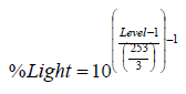
Where: %Light is the percent light output of the ballast and
-
Level is an 8-bit integer between 1 (0.1% light output) and 254 (100% output) that is adjusted for MinLevel and MaxLevel using the following equation:
Level = (MaxLevel – MinLevel) * CurrentLevel / 253 + (254 * MinLevel – MaxLevel) / 253.
Note 1: Value 255 is not used.
Note 2: The light output is determined by this curve together with the IntrinsicBallastFactor and BallastFactorAdjustment attributes.
The table below gives a couple of examples of the dimming light curve for different values of MinLevel, MaxLevel and CurrentLevel.
| MinLevel | MaxLevel | CurrentLevel | Level | %Light |
|---|---|---|---|---|
|
1 |
254 |
1 |
1 |
0.10% |
|
1 |
254 |
10 |
10 |
0.13% |
|
1 |
254 |
100 |
100 |
1.49% |
|
1 |
254 |
254 |
254 |
100% |
|
170 |
254 |
1 |
170 |
10.1% |
|
170 |
254 |
10 |
173 |
11.0% |
|
170 |
254 |
100 |
203 |
24.8% |
|
170 |
254 |
254 |
254 |
100% |
|
170 |
230 |
1 |
170 |
10.1% |
|
170 |
230 |
10 |
172 |
10.7% |
|
170 |
230 |
100 |
193 |
19.2% |
|
170 |
230 |
254 |
230 |
51.9% |
4. HVAC
The Cluster Library is made of individual chapters such as this one. References between chapters are made using a X.Y notation where X is the chapter and Y is the sub-section within that chapter.
4.1. General Description
4.1.1. Introduction
The clusters specified in this document are for use typically in HVAC applications, but MAY be used in any application domain.
4.1.2. Terms
Precooling: Cooling a building in the early (cooler) part of the day, so that the thermal mass of the building decreases cooling needs in the later (hotter) part of the day.
4.1.3. Cluster List
This section lists the clusters specified in this document and gives examples of typical usage for the purpose of clarification. The clusters defined in this document are listed in Clusters Specified in the HVAC Functional Domain :
| ID | Cluster Name | Description |
|---|---|---|
|
0x0200 |
Pump Configuration and Control |
An interface for configuring and controlling pumps. |
|
0x0201 |
Thermostat |
An interface for configuring and controlling the functionality of a thermostat |
|
0x0202 |
Fan Control |
An interface for controlling a fan in a heating / cooling system |
|
0x0204 |
Thermostat User Interface Configuration |
An interface for configuring the user interface of a thermostat (which MAY be remote from the thermostat) |


4.2. Pump Configuration and Control Cluster
The Pump Configuration and Control cluster provides an interface for the setup and control of pump devices, and the automatic reporting of pump status information. Note that control of pump speed is not included – speed is controlled by the On/Off and Level Control clusters.
4.2.2.
4.2.1.
Revision
History
The global ClusterRevision attribute value SHALL be the highest revision number in the table below.
| Revision | Description |
|---|---|
|
1 |
|
|
2 |
All Hubs changes |
|
3 |
New data model format and notation, added additional events |
|
4 | Added feature map |
4.2.3.
4.2.2.
Classification
| Hierarchy | Role |
|
|
|---|---|---|---|
|
Base |
Application |
|
|
4.2.4. Features
This cluster SHALL support the FeatureMap bitmap attribute as defined below.
| Bit | Code | Feature | Conformance | Summary |
|---|---|---|---|---|
0 | PRSCONST | ConstantPressure | O.a+ | Supports operating in constant pressure mode |
1 | PRSCOMP | CompensatedPressure | O.a+ | Supports operating in compensated pressure mode |
2 | FLW | ConstantFlow | O.a+ | Supports operating in constant flow mode |
3 | SPD | ConstantSpeed | O.a+ | Supports operating in constant speed mode |
4 | TEMP | ConstantTemperature | O.a+ | Supports operating in constant temperature mode |
5 | AUTO | Automatic | O | Supports operating in automatic mode |
6 | LOCAL | LocalOperation | O | Supports operating using local settings |
4.2.5. Dependencies
Where
external
pressure,
flow,
and
temperature
measurements
are
processed
by
this
cluster
(see
Values
of
the
ControlMode
Attribute
),
attribute),
these
are
provided
by
a
Pressure
Measurement
cluster,
a
Flow
Measurement
cluster,
and
a
Temperature
Measurement
client
cluster,
respectively.
These
3
client
clusters
are
used
for
connection
to
a
remote
sensor
device.
The
pump
is
able
to
use
the
sensor
measurement
provided
by
a
remote
sensor
for
regulation
of
the
pump
speed.
Note
that
control
of
the
pump
setpoint
is
not
included
in
this
cluster
–
the
On/Off
and
Level
Control
clusters
(see
Typical
Usage
of
Pump
Configuration
and
Control
Cluster
)
MAY
be
used
by
a
pump
device
to
turn
it
on
and
off
and
control
its
setpoint.
Note
that
the
Pump
Configuration
and
Control
cluster
MAY
override
on/off/setpoint
settings
for
specific
operation
modes
(See
section
OperationMode
Attribute
attribute
for
detailed
description
of
the
operation
and
control
of
the
pump.).
4.2.6.
Pump
Information
Attributes
Data
Types
4.2.6.1. PumpStatusBitmap
This data type is derived from map16.
| Bit | Name | Summary |
|---|---|---|
0 | DeviceFault | A fault related to the system or pump device is detected. |
1 | SupplyFault | A fault related to the supply to the pump is detected. |
2 | SpeedLow | Setpoint is too low to achieve. |
3 | SpeedHigh | Setpoint is too high to achieve. |
4 | LocalOverride | Device control is overridden by hardware, such as an external STOP button or via a local HMI. |
5 | Running |
Pump
|
6 | RemotePressure | A remote pressure sensor is used as the sensor for the regulation of the pump. |
7 | RemoteFlow | A remote flow sensor is used as the sensor for the regulation of the pump. |
8 | RemoteTemperature | A remote temperature sensor is used as the sensor for the regulation of the pump. |
4.2.6.1.1. DeviceFault Bit
If this bit is set, it MAY correspond to an event in the range 2-16, see Events .
4.2.6.1.2. SupplyFault Bit
If this bit is set, it MAY correspond to an event in the range 0-1 or 13, see Events .
4.2.6.1.3. LocalOverride Bit
While this bit is set, the EffectiveOperationMode is adjusted to Local. Any request changing OperationMode SHALL generate a FAILURE error status until LocalOverride is cleared on the physical device. When LocalOverride is cleared, the device SHALL return to the operation mode set in OperationMode.
4.2.6.1.4. RemotePressure Bit
If this bit is set, EffectiveControlMode is ConstantPressure and the setpoint for the pump is interpreted as a percentage of the range of the remote sensor ([MinMeasuredValue – MaxMeasuredValue]).
4.2.6.2. OperationModeEnum
This data type is derived from enum8.
| Value | Name | Summary | Conformance |
|---|---|---|---|
0 | Normal | The pump is controlled by a setpoint, as defined by a connected remote sensor or by the ControlMode attribute. | M |
1 | Minimum | This value sets the pump to run at the minimum possible speed it can without being stopped. | SPD |
2 | Maximum | This value sets the pump to run at its maximum possible speed. | SPD |
3 | Local | This value sets the pump to run with the local settings of the pump, regardless of what these are. | LOCAL |
4.2.6.3. ControlModeEnum
This data type is derived from enum8.
| Value | Name | Summary | Conformance |
|---|---|---|---|
0 | ConstantSpeed | The pump is running at a constant speed. | SPD |
1 | ConstantPressure | The pump will regulate its speed to maintain a constant differential pressure over its flanges. | PRSCONST |
2 | ProportionalPressure | The pump will regulate its speed to maintain a constant differential pressure over its flanges. | PRSCOMP |
3 | ConstantFlow | The pump will regulate its speed to maintain a constant flow through the pump. | FLW |
5 | ConstantTemperature | The pump will regulate its speed to maintain a constant temperature. | TEMP |
7 | Automatic | The operation of the pump is automatically optimized to provide the most suitable performance with respect to comfort and energy savings. | AUTO |
4.2.6.3.1. ConstantSpeed Value
The setpoint is interpreted as a percentage of the range derived from the [MinConstSpeed – MaxConstSpeed] attributes.
4.2.6.3.2. ConstantPressure Value
The setpoint is interpreted as a percentage of the range of the sensor used for this control mode. In case of the internal pressure sensor, this will be the range derived from the [MinConstPressure – MaxConstPressure] attributes. In case of a remote pressure sensor, this will be the range derived from the [MinMeasuredValue – MaxMeasuredValue] attributes of the remote pressure sensor.
4.2.6.3.3. ProportionalPressure Value
The setpoint is interpreted as a percentage of the range derived of the [MinCompPressure – MaxCompPressure] attributes. The internal setpoint will be lowered (compensated) dependent on the flow in the pump (lower flow ⇒ lower internal setpoint).
4.2.6.3.4. ConstantFlow Value
The setpoint is interpreted as a percentage of the range of the sensor used for this control mode. In case of the internal flow sensor, this will be the range derived from the [MinConstFlow – MaxConstFlow] attributes. In case of a remote flow sensor, this will be the range derived from the [MinMeasuredValue – MaxMeasuredValue] attributes of the remote flow sensor.
4.2.6.3.5. ConstantTemperature Value
The setpoint is interpreted as a percentage of the range of the sensor used for this control mode. In case of the internal temperature sensor, this will be the range derived from the [MinConstTemp – MaxConstTemp] attributes. In case of a remote temperature sensor, this will be the range derived from the [MinMeasuredValue – MaxMeasuredValue] attributes of the remote temperature sensor.
4.2.7. Attributes
| ID | Name | Type | Constraint | Quality |
|
|
Conformance |
|---|---|---|---|---|---|---|---|
|
|
MaxPressure |
int16 |
all |
|
|
|
M |
|
|
MaxSpeed |
uint16 |
all |
|
|
|
M |
|
|
MaxFlow |
uint16 |
all |
|
|
|
M |
|
|
MinConstPressure |
int16 |
all |
|
|
|
|
|
|
MaxConstPressure |
int16 |
all |
|
|
|
|
|
|
MinCompPressure |
int16 |
all |
|
|
|
|
|
|
MaxCompPressure |
int16 |
all |
|
|
|
|
|
|
MinConstSpeed |
uint16 |
all |
|
|
|
|
|
|
MaxConstSpeed |
uint16 |
all |
|
|
|
|
|
|
MinConstFlow |
uint16 |
all |
|
|
|
|
|
|
MaxConstFlow |
uint16 |
all |
| null |
R V |
FLW, [AUTO] |
0x000b | MinConstTemp | int16 | -27315 to max | X F | null |
| TEMP, [AUTO] |
|
|
|
int16 |
-27315 to max |
| null |
R V |
|
0x0010 | PumpStatus | desc | P | 0 | R V |
O |
|
|
|
| desc | N | desc | R V | M | |
0x0012 | EffectiveControlMode | desc | N | desc | R V | M | |
0x0013 | Capacity |
int16 |
|
| null | R V | M |
0x0014 | Speed | uint16 | all | X | null |
R V |
O |
0x0015 | LifetimeRunningHours | uint24 | all | X N | 0 | RW VM | O |
0x0016 | Power | uint24 | all | X | null |
R V | O |
|
0x0017 | LifetimeEnergyConsumed | uint32 | all | X N | 0 | RW VM | O |
0x0020 | OperationMode | desc | N | 0 | RW VM | M | |
0x0021 | ControlMode | desc | N | 0 | RW VM | O | |
0x0022 | AlarmMask | map16 | desc | N | 0 | R V | D |
4.2.6.1.
4.2.7.1.
MaxPressure
Attribute
The
MaxPressure
This
attribute
specifies
the
maximum
pressure
the
pump
can
achieve.
It
is
a
physical
limit,
and
does
not
apply
to
any
specific
control
mode
or
operation
mode.
Valid
range
is
-3,276.7
kPa
to
3,276.7
kPa
(steps
of
0.1
kPa).
The
MaxPressure
This
attribute
SHALL
be
null
if
the
value
is
invalid.
4.2.6.2.
4.2.7.2.
MaxSpeed
Attribute
The
MaxSpeed
This
attribute
specifies
the
maximum
speed
the
pump
can
achieve.
It
is
a
physical
limit,
and
does
not
apply
to
any
specific
control
mode
or
operation
mode.
Valid
range
is
0
to
65,534
RPM
(steps
of
1
RPM).
The
MaxSpeed
This
attribute
SHALL
be
null
if
the
value
is
invalid.
4.2.6.3.
4.2.7.3.
MaxFlow
Attribute
The
MaxFlow
This
attribute
specifies
the
maximum
flow
the
pump
can
achieve.
It
is
a
physical
limit,
and
does
not
apply
to
any
specific
control
mode
or
operation
mode.
Valid
range
is
0
m
3
/h
to
6,553.4
m
3
/h
(steps
of
0.1
m
3
/h).
The
MaxFlow
This
attribute
SHALL
be
null
if
the
value
is
invalid.
4.2.6.4.
4.2.7.4.
MinConstPressure
Attribute
The
MinConstPressure
This
attribute
specifies
the
minimum
pressure
the
pump
can
achieve
when
it
is
working
with
the
ControlMode
attribute
set
to
ConstantPressure.
Valid
range
is
–3,276.7
kPa
to
3,276.7
kPa
(steps
of
0.1
kPa).
The
MinConstPressure
This
attribute
SHALL
be
null
if
the
value
is
invalid.
4.2.6.5.
4.2.7.5.
MaxConstPressure
Attribute
The
MaxConstPressure
This
attribute
specifies
the
maximum
pressure
the
pump
can
achieve
when
it
is
working
with
the
ControlMode
attribute
set
to
ConstantPressure.
Valid
range
is
–3,276.7
kPa
to
3,276.7
kPa
(steps
of
0.1
kPa).
The
MaxConstPressure
This
attribute
SHALL
be
null
if
the
value
is
invalid.
4.2.6.6.
4.2.7.6.
MinCompPressure
Attribute
The
MinCompPressure
This
attribute
specifies
the
minimum
compensated
pressure
the
pump
can
achieve
when
it
is
working
with
the
ControlMode
attribute
set
to
ProportionalPressure.
Valid
range
is
–3,276.7
kPa
to
3,276.7
kPa
(steps
of
0.1
kPa).
The
MinCompPressure
This
attribute
SHALL
be
null
if
the
value
is
invalid.
4.2.6.7.
4.2.7.7.
MaxCompPressure
Attribute
The
MaxCompPressure
This
attribute
specifies
the
maximum
compensated
pressure
the
pump
can
achieve
when
it
is
working
with
the
ControlMode
attribute
set
to
ProportionalPressure.
Valid
range
is
–3,276.7
kPa
to
3,276.7
kPa
(steps
of
0.1
kPa).
The
MaxCompPressure
This
attribute
SHALL
be
null
if
the
value
is
invalid.
4.2.6.8.
4.2.7.8.
MinConstSpeed
Attribute
The
MinConstSpeed
This
attribute
specifies
the
minimum
speed
the
pump
can
achieve
when
it
is
working
with
the
ControlMode
attribute
set
to
ConstantSpeed.
Valid
range
is
0
to
65,534
RPM
(steps
of
1
RPM).
The
MinConstSpeed
This
attribute
SHALL
be
null
if
the
value
is
invalid.
4.2.6.9.
4.2.7.9.
MaxConstSpeed
Attribute
The
MaxConstSpeed
This
attribute
specifies
the
maximum
speed
the
pump
can
achieve
when
it
is
working
with
the
ControlMode
attribute
set
to
ConstantSpeed.
Valid
range
is
0
to
65,534
RPM
(steps
of
1
RPM).
The
MaxConstSpeed
This
attribute
SHALL
be
null
if
the
value
is
invalid.
4.2.6.10.
4.2.7.10.
MinConstFlow
Attribute
The
MinConstFlow
This
attribute
specifies
the
minimum
flow
the
pump
can
achieve
when
it
is
working
with
the
ControlMode
attribute
set
to
ConstantFlow.
Valid
range
is
0
m
3
/h
to
6,553.4
m
3
/h
(steps
of
0.1
m
3
/h).
The
MinConstFlow
This
attribute
SHALL
be
null
if
the
value
is
invalid.
4.2.6.11.
4.2.7.11.
MaxConstFlow
Attribute
The
MaxConstFlow
This
attribute
specifies
the
maximum
flow
the
pump
can
achieve
when
it
is
working
with
the
ControlMode
attribute
set
to
ConstantFlow.
Valid
range
is
0
m
3
/h
to
6,553.4
m
3
/h
(steps
of
0.1
m
3
/h).
The
MaxConstFlow
This
attribute
SHALL
be
null
if
the
value
is
invalid.
4.2.6.12.
4.2.7.12.
MinConstTemp
Attribute
The
MinConstTemp
This
attribute
specifies
the
minimum
temperature
the
pump
can
maintain
in
the
system
when
it
is
working
with
the
ControlMode
attribute
set
to
ConstantTemperature.
Valid
range
is
–273.15
°C
to
327.67
°C
(steps
of
0.01
°C).
The
MinConstTemp
This
attribute
SHALL
be
null
if
the
value
is
invalid.
4.2.6.13.
4.2.7.13.
MaxConstTemp
Attribute
The
MaxConstTemp
This
attribute
specifies
the
maximum
temperature
the
pump
can
maintain
in
the
system
when
it
is
working
with
the
ControlMode
attribute
set
to
ConstantTemperature.
MaxConstTemp
SHALL
be
greater
than
or
equal
to
_MinConstTemp_
MinConstTemp
Valid
range
is
–273.15
°C
to
327.67
°C
(steps
of
0.01
°C).
The
MaxConstTemp
This
attribute
SHALL
be
null
if
the
value
is
invalid.
4.2.7.1.
4.2.7.14.
PumpStatus
Attribute
The
PumpStatus
This
attribute
specifies
the
activity
status
of
the
pump
functions
as
listed
in
Values
of
the
PumpStatus
Attribute
PumpStatusBitmap
.
Where
a
pump
controller
function
is
active,
the
corresponding
bit
SHALL
be
set
to
1.
Where
a
pump
controller
function
is
not
active,
the
corresponding
bit
SHALL
be
set
to
0.
4.2.7.2.
4.2.7.15.
EffectiveOperationMode
Attribute
The
EffectiveOperationMode
This
attribute
specifies
current
effective
operation
mode
of
the
pump.
pump
as
defined
in
OperationModeEnum
.
The
value
of
the
EffectiveOperationMode
attribute
is
the
same
as
the
OperationMode
attribute,
but
if
unless
one
of
the
following
points
are
true:
The pump is physically set to run with the local settings
or the-
The LocalOverride bit in the PumpStatus attribute is set,
the value MAY be different from the OperationMode attribute.
See
section
OperationMode
Attribute
and
ControlMode
attributes
for
a
detailed
description
of
the
operation
and
control
of
the
pump.
4.2.7.3.
4.2.7.16.
EffectiveControlMode
Attribute
The
EffectiveControlMode
This
attribute
specifies
the
current
effective
control
mode
of
the
pump.
pump
as
defined
in
ControlModeEnum
.
The
EffectiveControlMode
This
attribute
contains
the
control
mode
that
currently
applies
to
the
pump.
It
will
have
the
value
of
the
ControlMode
attribute,
unless
a
one
of
the
following
points
are
true:
The ControlMode attribute is set to Automatic. In this case, the value of the EffectiveControlMode SHALL match the behavior of the pump.
A remote sensor is used as the sensor for regulation of the pump. In this case, EffectiveControlMode will display ConstantPressure, ConstantFlow or ConstantTemperature if the remote sensor is a pressure sensor, a flow sensor or a temperature sensor respectively, regardless of the value of the ControlMode attribute.
In case the ControlMode attribute is not included on the device and no remote sensors are connected, the value of the EffectiveControlMode SHALL match the vendor-specific behavior of the pump.
See
section
OperationMode
Attribute
and
ControlMode
attributes
for
detailed
a
description
of
the
operation
and
control
of
the
pump.
4.2.7.4.
4.2.7.17.
Capacity
Attribute
The
Capacity
This
attribute
specifies
the
actual
capacity
of
the
pump
as
a
percentage
of
the
effective
maximum
setpoint
value.
It
is
updated
dynamically
as
the
speed
of
the
pump
changes.
If the value is not available (the measurement or estimation of the speed is done in the pump), this attribute will indicate the null value.
Valid
range
is
0
%
to
163.835%
(0.005
%
granularity).
Although
the
Capacity
this
attribute
is
a
signed
value,
values
of
capacity
less
than
zero
have
no
physical
meaning.
4.2.7.5.
4.2.7.18.
Speed
Attribute
The
Speed
This
attribute
specifies
the
actual
speed
of
the
pump
measured
in
RPM.
It
is
updated
dynamically
as
the
speed
of
the
pump
changes.
If the value is not available (the measurement or estimation of the speed is done in the pump), this attribute will indicate the null value.
Valid
range
is
0
to
65.534
RPM.
4.2.7.6.
4.2.7.19.
LifetimeRunningHours
Attribute
The
LifetimeRunningHours
This
attribute
specifies
the
accumulated
number
of
hours
that
the
pump
has
been
powered
and
the
motor
has
been
running.
It
is
updated
dynamically
as
it
increases.
It
is
preserved
over
power
cycles
of
the
pump.
If
LifeTimeRunningHours
rises
above
maximum
value
it
“rolls
over”
and
starts
at
0
(zero).
This attribute is writeable, in order to allow setting to an appropriate value after maintenance. If the value is not available, this attribute will indicate the null value.
Valid
range
is
0
to
16,777,214
hrs.
4.2.7.7.
4.2.7.20.
Power
Attribute
The
Power
This
attribute
specifies
the
actual
power
consumption
of
the
pump
in
Watts.
The
value
of
the
Power
this
attribute
is
updated
dynamically
as
the
power
consumption
of
the
pump
changes.
This attribute is read only. If the value is not available (the measurement of power consumption is not done in the pump), this attribute will indicate the null value.
Valid
range
is
0
to
16,777,214
Watts.
4.2.7.8.
4.2.7.21.
LifetimeEnergyConsumed
Attribute
The
LifetimeEnergyConsumed
This
attribute
specifies
the
accumulated
energy
consumption
of
the
pump
through
the
entire
lifetime
of
the
pump
in
kWh.
The
value
of
the
LifetimeEnergyConsumed
attribute
is
updated
dynamically
as
the
energy
consumption
of
the
pump
increases.
If
LifetimeEnergyConsumed
rises
above
maximum
value
it
“rolls
over”
and
starts
at
0
(zero).
This attribute is writeable, in order to allow setting to an appropriate value after maintenance.
Valid
range
is
0
kWh
to
4,294,967,294
kWh.
This
attribute
SHALL
be
null
if
the
value
is
unknown.
4.2.8.1.
4.2.7.22.
OperationMode
Attribute
The
OperationMode
This
attribute
specifies
the
operation
mode
of
the
pump.
This
attribute
SHALL
have
one
of
the
values
listed
pump
as
defined
in
Values
of
the
OperationMode
Attribute
OperationModeEnum
.
The
actual
operating
mode
of
the
pump
is
a
result
of
the
setting
of
the
attributes
OperationMode
,
OperationMode,
ControlMode
and
the
optional
connection
of
a
remote
sensor.
The
operation
and
control
is
prioritized
as
shown
in
the
scheme
in
Priority
Scheme
of
Pump
Operation
and
Control
:
below:
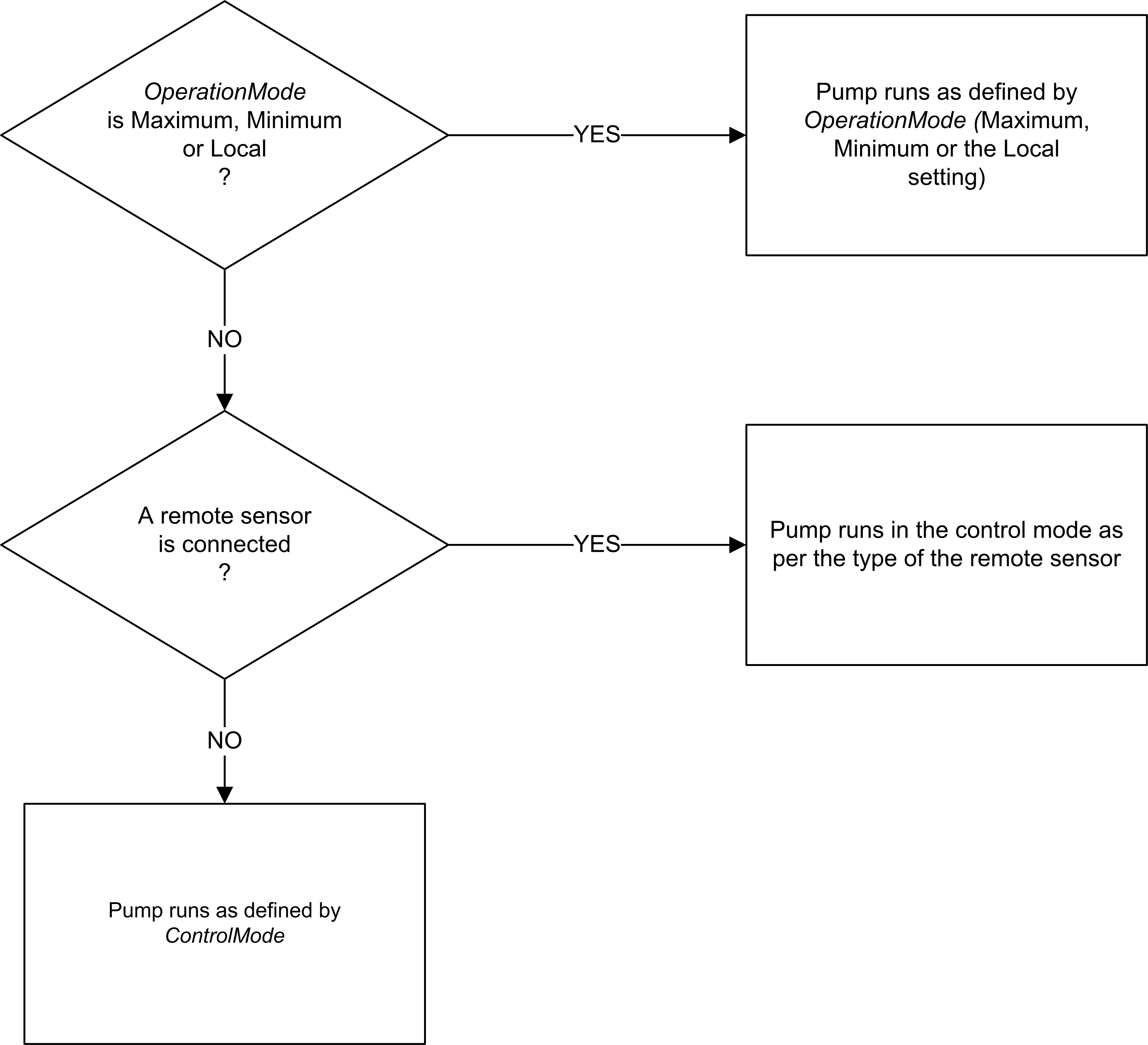
If
the
OperationMode
this
attribute
is
Maximum,
Minimum
or
Local,
the
OperationMode
attribute
decides
how
the
pump
is
operated.
If
the
OperationMode
this
attribute
is
Normal
and
a
remote
sensor
is
connected
to
the
pump,
the
type
of
the
remote
sensor
decides
the
control
mode
of
the
pump.
A
connected
remote
pressure
sensor
will
make
the
pump
run
in
control
mode
Constant
pressure
and
vice
versa
for
flow
and
temperature
type
sensors.
This
is
regardless
of
the
setting
of
the
ControlMode
attribute.
If
the
OperationMode
this
attribute
is
Normal
and
no
remote
sensor
is
connected,
the
control
mode
of
the
pump
is
decided
by
the
ControlMode
attribute.
OperationMode
MAY
be
changed
at
any
time,
even
when
the
pump
is
running.
The
behavior
of
the
pump
at
the
point
of
changing
the
value
of
the
OperationMode
this
attribute
is
vendor-specific.
In
the
OperationMode
Attribute
Value
Name
Description
0
Normal
The
pump
is
controlled
by
case
a
setpoint,
as
defined
by
device
does
not
support
a
connected
remote
sensor
or
by
specific
operation
mode,
the
ControlMode
attribute.
(N.B.
The
setpoint
is
write
interaction
to
this
attribute
with
an
internal
variable
which
MAY
unsupported
operation
mode
value
SHALL
be
controlled
between
0%
ignored
and
100%,
e.g.,
by
means
of
the
Level
Control
cluster)
1
Minimum
This
value
sets
the
pump
to
run
at
the
minimum
possible
speed
it
can
without
being
stopped
2
Maximum
This
value
sets
the
pump
to
run
at
its
maximum
possible
speed
3
Local
This
value
sets
the
pump
to
run
with
the
local
settings
of
a
response
containing
the
pump,
regardless
status
of
what
these
are
CONSTRAINT_ERROR
SHALL
be
returned.
4.2.8.2.
4.2.7.23.
ControlMode
Attribute
The
ControlMode
This
attribute
specifies
the
control
mode
of
the
pump.
This
attribute
SHALL
have
one
of
the
values
listed
pump
as
defined
in
Values
of
the
ControlMode
Attribute
ControlModeEnum
.
See
section
the
OperationMode
Attribute
attribute
for
a
detailed
description
of
the
operation
and
control
of
the
pump.
In
the
case
a
device
does
not
support
or
implement
a
specific
control
mode,
a
write
interaction
to
the
ControlMode
attribute
with
an
unsupported
control
mode
value
SHALL
be
ignored
and
a
response
containing
the
status
of
CONSTRAINT_ERROR
SHALL
be
returned.
ControlMode
MAY
be
changed
at
any
time,
even
when
the
pump
is
running.
The
behavior
of
the
pump
at
the
point
of
changing
is
vendor-specific.
In
case
of
the
internal
pressure
sensor,
this
will
be
the
range
derived
from
the
[
MinConstPressure
–
MaxConstPressure
]
attributes.
In
case
of
a
remote
pressure
sensor,
this
will
be
the
range
derived
from
the
[
MinMeasuredValue
–
MaxMeasuredValue
]
attributes
of
the
remote
pressure
sensor.
2
ProportionalPressure
The
pump
will
regulate
its
speed
to
maintain
a
constant
differential
pressure
over
its
flanges.
The
setpoint
is
interpreted
as
a
percentage
of
the
range
derived
of
the
[
MinCompPressure
–
MaxCompPressure
]
attributes.
The
internal
setpoint
will
be
lowered
(compensated)
dependent
on
the
flow
in
the
pump
(lower
flow
⇒
lower
internal
setpoint)
3
ConstantFlow
The
pump
will
regulate
its
speed
to
maintain
a
constant
flow
through
the
pump.
The
setpoint
is
interpreted
as
device
does
not
support
a
percentage
of
the
range
of
the
sensor
used
for
this
specific
control
mode.
In
case
of
the
internal
flow
sensor,
this
will
be
the
range
derived
from
the
[
MinConstFlow
–
MaxConstFlow
]
attributes.
In
case
of
a
remote
flow
sensor,
this
will
be
the
range
derived
from
the
[
MinMeasuredValue
–
MaxMeasuredValue
]
attributes
of
mode,
the
remote
flow
sensor.
5
ConstantTemperature
The
pump
will
regulate
its
speed
write
interaction
to
maintain
a
constant
temperature.
The
setpoint
is
interpreted
as
a
percentage
of
the
range
of
the
sensor
used
for
this
attribute
with
an
unsupported
control
mode.
In
case
of
the
internal
temperature
sensor,
this
will
mode
value
SHALL
be
the
range
derived
from
the
[
MinConstTemp
–
MaxConstTemp
]
attributes.
In
case
of
ignored
and
a
remote
temperature
sensor,
this
will
be
the
range
derived
from
the
[
MinMeasuredValue
–
MaxMeasuredValue
]
attributes
of
response
containing
the
remote
temperature
sensor.
7
Automatic
The
operation
status
of
the
pump
is
automatically
optimized
to
provide
the
most
suitable
performance
with
respect
to
comfort
and
energy
savings.
This
behavior
is
manufacturer
defined.
The
pump
can
CONSTRAINT_ERROR
SHALL
be
stopped
by
setting
the
setpoint
of
the
level
control
cluster
to
0,
or
by
using
the
On/Off
cluster.
If
the
pump
is
started
(at
any
setpoint),
the
speed
of
the
pump
is
entirely
determined
by
the
pump.
returned.
4.2.9.
4.2.8.
Events
| ID | Name | Priority | Access | Conformance |
|---|---|---|---|---|
|
|
SupplyVoltageLow |
|
V |
O |
|
|
SupplyVoltageHigh |
|
V |
O |
|
|
PowerMissingPhase |
|
V |
O |
|
|
SystemPressureLow |
|
V |
O |
|
|
SystemPressureHigh |
|
V |
O |
|
|
DryRunning |
|
V |
O |
|
|
MotorTemperatureHigh |
|
V |
O |
|
|
PumpMotorFatalFailure |
|
V |
O |
|
|
ElectronicTemperatureHigh |
|
V |
O |
|
|
PumpBlocked |
|
V |
O |
|
|
SensorFailure |
|
V |
O |
|
|
ElectronicNonFatalFailure |
|
V |
O |
|
|
ElectronicFatalFailure |
|
V |
O |
|
|
GeneralFault |
|
V |
O |
|
|
Leakage |
|
V |
O |
|
|
AirDetection |
|
V |
O |
|
|
TurbineOperation |
|
V |
O |
4.3. Thermostat Cluster
This cluster provides an interface to the functionality of a thermostat.
4.3.1. Revision History
The global ClusterRevision attribute value SHALL be the highest revision number in the table below.
| Revision | Description |
|---|---|
|
1 |
mandatory global ClusterRevision attribute added; fixed some defaults; CCB 1823, 1480 |
|
2 |
CCB 1981 2186 2249 2250 2251; NFR Thermostat Setback |
|
3 |
CCB 2477 2560 2773 2777 2815 2816 3029 |
|
4 |
All Hubs changes |
|
5 |
New data model format and notation, added FeatureMap, collapsed attribute sets, clarified edge cases around limits, default value of xxxSetpointLimit now respects AbsxxxSetpointLimit |
|
6 | Introduced the LTNE feature and adapted text (spec issue #5778) |
4.3.2. Classification
| Hierarchy | Role | Context | PICS Code | Primary Transaction |
|---|---|---|---|---|
|
Base |
Application |
Endpoint |
TSTAT |
Type 2 (server to client) |
4.3.3. Cluster Identifiers
| Identifier | Name |
|---|---|
|
0x0201 |
Thermostat |
4.3.3.1. Features
This cluster SHALL support the FeatureMap bitmap attribute as defined below.
| Bit | Code | Feature | Description | Conformance |
|---|---|---|---|---|
|
0 |
HEAT |
Heating |
Thermostat is capable of managing a heating device |
|
|
1 |
COOL |
Cooling |
Thermostat is capable of managing a cooling device |
|
|
2 |
OCC |
Occupancy |
Supports Occupied and Unoccupied setpoints |
O |
|
3 |
SCH |
Schedule Configuration |
Supports remote configuration of a weekly schedule of setpoint transitions |
O |
|
4 |
SB |
Setback |
Supports configurable setback (or span) |
O |
|
5 |
AUTO |
Auto Mode |
Supports a System Mode of Auto |
O |
|
6 | LTNE | Local Temperature Not Exposed | Thermostat does not expose the LocalTemperature Value in the LocalTemperature attribute | O |
4.3.3.1.1. Local Temperature Not Exposed (LTNE) feature
This feature indicates that the LocalTemperature Value used internally is unavailable to report externally, for example due to the temperature control being done by a separate subsystem which does not offer a view into the currently measured temperature, but allows setpoints to be provided.
4.3.4. Units of Temperature
Temperatures within this cluster are represented by types using units of degree Celsius.
While temperature values MUST be transferred over the air using these types, this does not limit how Thermostats may display or store temperature values. Thermostats which display temperature values SHOULD follow the recommendations in Conversion of Temperature Values for Display
|
Caution
|
Calculations
with
temperature
attributes
Where calculations or comparisons are performed, attribute values must be converted to a common type. In many cases, it is not sufficient to simply use the integer representation as the scaling from °C to integer value differs. |
4.3.5. Setpoint Limits
There are a number of attributes which impose limits on setpoint values. This imposes constraints which MUST be maintained by any mechanism which modifies a limit or setpoint. Individual attribute descriptions detail the actions to be taken should a conflict arise while modifying the value.
User configurable limits must be within device limits:
-
AbsMinHeatSetpointLimit \$<=\$ MinHeatSetpointLimit \$<=\$ MaxHeatSetpointLimit \$<=\$ AbsMaxHeatSetpointLimit
-
AbsMinCoolSetpointLimit \$<=\$ MinCoolSetpointLimit \$<=\$ MaxCoolSetpointLimit \$<=\$ AbsMaxCoolSetpointLimit
Setpoints must be within user configurable limits:
-
MinHeatSetpointLimit \$<=\$ OccupiedHeatingSetpoint \$<=\$ MaxHeatSetpointLimit
-
MinCoolSetpointLimit \$<=\$ OccupiedCoolingSetpoint \$<=\$ MaxCoolSetpointLimit
-
MinHeatSetpointLimit \$<=\$ UnoccupiedHeatingSetpoint \$<=\$ MaxHeatSetpointLimit
-
MinCoolSetpointLimit \$<=\$ UnoccupiedCoolingSetpoint \$<=\$ MaxCoolSetpointLimit
and if, and only if, the AUTO feature is supported, a deadband must be maintained between Heating and Cooling setpoints and limits:
-
AbsMinHeatSetpointLimit \$<=\$ (AbsMinCoolSetpointLimit - MinSetpointDeadBand)
-
AbsMaxHeatSetpointLimit \$<=\$ (AbsMaxCoolSetpointLimit - MinSetpointDeadBand)
-
MinHeatSetpointLimit \$<=\$ (MinCoolSetpointLimit - MinSetpointDeadBand)
-
MaxHeatSetpointLimit \$<=\$ (MaxCoolSetpointLimit - MinSetpointDeadBand)
-
OccupiedHeatingSetpoint \$<=\$ (OccupiedCoolingSetpoint - MinSetpointDeadBand)
-
UnoccupiedHeatingSetpoint \$<=\$ (UnoccupiedCoolingSetpoint - MinSetpointDeadBand)
4.3.6. Dependencies
If the Alarms server cluster is supported on the same endpoint then the Alarms functionality is enabled and the AlarmMask attribute SHALL be supported. For remote temperature sensing, the Temperature Measurement client cluster MAY be included on the same endpoint. For occupancy sensing, the Occupancy Sensing client cluster MAY be included on the same endpoint.
4.3.7. Attributes
| Id | Name | Type | Constraint | Quality | Default | Access | Conformance |
|---|---|---|---|---|---|---|---|
|
0x0000 |
LocalTemperature |
all |
XP |
null |
R V |
M |
|
|
0x0001 |
OutdoorTemperature |
all |
X |
null |
R V |
O |
|
|
0x0002 |
Occupancy |
map8 |
desc |
1 |
R V |
OCC |
|
|
0x0003 |
AbsMinHeatSetpointLimit |
desc |
F |
7°C |
R V |
[HEAT] |
|
|
0x0004 |
AbsMaxHeatSetpointLimit |
desc |
F |
30°C |
R V |
[HEAT] |
|
|
0x0005 |
AbsMinCoolSetpointLimit |
desc |
F |
16°C |
R V |
[COOL] |
|
|
0x0006 |
AbsMaxCoolSetpointLimit |
desc |
F |
32°C |
R V |
[COOL] |
|
|
0x0007 |
PICoolingDemand |
uint8 |
0% to 100% |
P |
- |
R V |
[COOL] |
|
0x0008 |
PIHeatingDemand |
uint8 |
0% to 100% |
P |
- |
R V |
[HEAT] |
|
0x0009 |
HVACSystemTypeConfiguration |
map8 |
desc |
N |
0 |
R[W] VM |
D |
|
0x0010 |
LocalTemperatureCalibration |
-2.5°C to 2.5°C |
N |
0°C |
RW VM |
|
|
|
0x0011 |
OccupiedCoolingSetpoint |
desc |
NS |
26°C |
RW VO |
COOL |
|
|
0x0012 |
OccupiedHeatingSetpoint |
desc |
NS |
20°C |
RW VO |
HEAT |
|
|
0x0013 |
UnoccupiedCoolingSetpoint |
desc |
N |
26°C |
RW VO |
COOL & OCC |
|
|
0x0014 |
UnoccupiedHeatingSetpoint |
desc |
N |
20°C |
RW VO |
HEAT & OCC |
|
|
0x0015 |
MinHeatSetpointLimit |
desc |
N |
AbsMinHeatSetpointLimit |
RW VM |
[HEAT] |
|
|
0x0016 |
MaxHeatSetpointLimit |
desc |
N |
AbsMaxHeatSetpointLimit |
RW VM |
[HEAT] |
|
|
0x0017 |
MinCoolSetpointLimit |
desc |
N |
AbsMinCoolSetpointLimit |
RW VM |
[COOL] |
|
|
0x0018 |
MaxCoolSetpointLimit |
desc |
N |
AbsMaxCoolSetpointLimit |
RW VM |
[COOL] |
|
|
0x0019 |
MinSetpointDeadBand |
0°C to 2.5°C |
N |
2.5°C |
R[W] VM |
AUTO |
|
|
0x001a |
RemoteSensing |
map8 |
00000xxx |
N |
0 |
RW VM |
O |
|
0x001b |
ControlSequenceOfOperation |
enum8 |
desc |
N |
4 |
RW VM |
M |
|
0x001c |
SystemMode |
enum8 |
desc |
NS |
1 |
RW VM |
M |
|
0x001d |
AlarmMask |
map8 |
desc |
0 |
R V |
O |
|
|
0x001e |
ThermostatRunningMode |
enum8 |
desc |
0 |
R V |
[AUTO] |
|
|
0x0020 |
StartOfWeek |
enum8 |
desc |
F |
– |
R V |
SCH |
|
0x0021 |
NumberOfWeeklyTransitions |
uint8 |
all |
F |
0 |
R V |
SCH |
|
0x0022 |
NumberOfDailyTransitions |
uint8 |
all |
F |
0 |
R V |
SCH |
|
0x0023 |
TemperatureSetpointHold |
enum8 |
desc |
N |
0 |
RW VM |
O |
|
0x0024 |
TemperatureSetpointHoldDuration |
uint16 |
0 to 1440 |
NX |
null |
RW VM |
O |
|
0x0025 |
ThermostatProgrammingOperationMode |
map8 |
desc |
P |
0 |
RW VM |
O |
|
0x0029 |
ThermostatRunningState |
map16 |
desc |
- |
R V |
O |
|
|
0x0030 |
SetpointChangeSource |
enum8 |
desc |
0 |
R V |
O |
|
|
0x0031 |
SetpointChangeAmount |
all |
X |
null |
R V |
O |
|
|
0x0032 |
SetpointChangeSourceTimestamp |
utc |
all |
0 |
R V |
O |
|
|
0x0034 |
OccupiedSetback |
OccupiedSetbackMin to OccupiedSetbackMax |
XN |
null |
RW VM |
SB |
|
|
0x0035 |
OccupiedSetbackMin |
0 to OccupiedSetbackMax |
XF |
null |
R V |
SB |
|
|
0x0036 |
OccupiedSetbackMax |
OccupiedSetbackMin to 25.4°C |
XF |
null |
R V |
SB |
|
|
0x0037 |
UnoccupiedSetback |
UnoccupiedSetbackMin to UnoccupiedSetbackMax |
XN |
null |
RW VM |
SB & OCC |
|
|
0x0038 |
UnoccupiedSetbackMin |
0 to UnoccupiedSetbackMax |
XF |
null |
R V |
SB & OCC |
|
|
0x0039 |
UnoccupiedSetbackMax |
UnoccupiedSetbackMin to 25.4°C |
XF |
null |
R V |
SB & OCC |
|
|
0x003a |
EmergencyHeatDelta |
all |
N |
25.5°C |
RW VM |
O |
|
|
0x0040 |
ACType |
enum8 |
desc |
N |
0 |
RW VM |
O |
|
0x0041 |
ACCapacity |
uint16 |
all |
N |
0 |
RW VM |
O |
|
0x0042 |
ACRefrigerantType |
enum8 |
desc |
N |
0 |
RW VM |
O |
|
0x0043 |
ACCompressorType |
enum8 |
desc |
N |
0 |
RW VM |
O |
|
0x0044 |
ACErrorCode |
map32 |
all |
0 |
RW VM |
O |
|
|
0x0045 |
ACLouverPosition |
enum8 |
desc |
N |
0 |
RW VM |
O |
|
0x0046 |
ACCoilTemperature |
all |
X |
null |
R V |
O |
|
|
0x0047 |
ACCapacityFormat |
enum8 |
desc |
N |
0 |
RW VM |
O |
4.3.7.1.
LocalTemperature
Attribute
Value
This
attribute
value
represents
the
current
temperature,
as
measured
locally
or
remotely
(over
the
network),
including
any
adjustments
applied
by
LocalTemperatureCalibration
attribute
(if
any)
as
follows:
LocalTemperature = ( measured temperature ) + LocalTemperatureCalibration .
The
null
value
indicates
that
the
temperature
measurement
is
invalid.
All
setpoint
attributes
in
the
Thermostat
cluster
SHALL
be
triggered
based
off
the
LocalTemperature
attribute
value
(i.e.,
measured
temperature
and
any
calibration
offset).
If the Local Temperature Not Exposed (LTNE) feature is present, the behavior of the thermostat SHALL be that the equipment’s temperature control uses the LocalTemperature value even if the current value of LocalTemperature is not reported in the LocalTemperature Attribute .
4.3.7.2. LocalTemperature Attribute
This attribute indicates the current LocalTemperature value , when available. The value may be local, or remote, depending on the value of the RemoteSensing attribute when supported.
If the
LTNEfeature is not supported:If the temperature measurement is invalid or currently unavailable, the attribute SHALL report
null.If the temperature measurement is valid, the attribute SHALL report that value.
Otherwise, if the
LTNEfeature is supported, there is no feedback externally available for the LocalTemperature value. In that case, the LocalTemperature attribute SHALL always reportnull.
4.3.7.2.
4.3.7.3.
OutdoorTemperature
Attribute
This attribute represents the outdoor temperature, as measured locally or remotely (over the network).
4.3.7.3.
4.3.7.4.
Occupancy
Attribute
This attribute specifies whether the heated/cooled space is occupied or not, as measured locally or remotely (over the network). If bit 0 = 1, the space is occupied, else it is unoccupied. All other bits are reserved.
4.3.7.4.
4.3.7.5.
AbsMinHeatSetpointLimit
Attribute
This attribute specifies the absolute minimum level that the heating setpoint MAY be set to. This is a limitation imposed by the manufacturer.
Refer to Setpoint Limits for constraints
4.3.7.5.
4.3.7.6.
AbsMaxHeatSetpointLimit
Attribute
This attribute specifies the absolute maximum level that the heating setpoint MAY be set to. This is a limitation imposed by the manufacturer.
Refer to Setpoint Limits for constraints
4.3.7.6.
4.3.7.7.
AbsMinCoolSetpointLimit
Attribute
This attribute specifies the absolute minimum level that the cooling setpoint MAY be set to. This is a limitation imposed by the manufacturer.
Refer to Setpoint Limits for constraints
4.3.7.7.
4.3.7.8.
AbsMaxCoolSetpointLimit
Attribute
This attribute specifies the absolute maximum level that the cooling setpoint MAY be set to. This is a limitation imposed by the manufacturer.
Refer to Setpoint Limits for constraints
4.3.7.8.
4.3.7.9.
PICoolingDemand
Attribute
This attribute specifies the level of cooling demanded by the PI (proportional integral) control loop in use by the thermostat (if any), in percent. This value is 0 when the thermostat is in “off” or “heating” mode.
This attribute is reported regularly and MAY be used to control a cooling device.
4.3.7.9.
4.3.7.10.
PIHeatingDemand
Attribute
This attribute specifies the level of heating demanded by the PI loop in percent. This value is 0 when the thermostat is in “off” or “cooling” mode.
This attribute is reported regularly and MAY be used to control a heating device.
4.3.7.10.
4.3.7.11.
HVACSystemTypeConfiguration
Attribute
This attribute specifies the HVAC system type controlled by the thermostat. If the thermostat uses physical DIP switches to set these parameters, this information SHALL be available read-only from the DIP switches. If these parameters are set via software, there SHALL be read/write access in order to provide remote programming capability. The meanings of individual bits are detailed below. Each bit represents a type of system configuration.
| Bit | Name | Description |
|---|---|---|
|
0 – 1 |
CoolingStage |
00
–
Cool
Stage
1
|
|
2 – 3 |
HeatingStage |
00
–
Heat
Stage
1
|
|
4 |
HeatingType |
0
–
Conventional
|
|
5 |
HeatingFuel |
0
–
Electric
/
B
|
4.3.7.11.
4.3.7.12.
LocalTemperatureCalibration
Attribute
This
attribute
specifies
the
offset
the
Thermostat
server
SHALL
make
to
the
measured
temperature
(locally
or
remotely)
before
calculating,
displaying,
or
communicating
to
adjust
the
LocalTemperature
attribute.
Value
prior
to
using,
displaying
or
reporting
it.
The
purpose
of
this
attribute
is
to
adjust
the
calibration
of
the
Thermostat
server
per
the
user’s
user’s
preferences
(e.g.,
to
match
if
there
are
multiple
servers
displaying
different
values
for
the
same
HVAC
area)
or
compensate
for
variability
amongst
temperature
sensors.
If
a
Thermostat
client
attempts
to
write
LocalTemperatureCalibration
attribute
to
an
unsupported
value
(e.g.,
out
of
the
range
supported
by
the
Thermostat
server),
the
Thermostat
server
SHALL
respond
with
a
Write
Attribute
Response
Command
with
a
status
of
SUCCESS
and
set
the
value
of
LocalTemperatureCalibration
to
the
upper
or
lower
limit
reached.
4.3.7.12.
4.3.7.13.
OccupiedCoolingSetpoint
Attribute
This attribute specifies the cooling mode setpoint when the room is occupied.
Refer to Setpoint Limits for constraints. If an attempt is made to set this attribute such that these constraints are violated, a response with the status code CONSTRAINT_ERROR SHALL be returned.
If the occupancy status of the room is unknown, this attribute SHALL be used as the cooling mode setpoint.
4.3.7.13.
4.3.7.14.
OccupiedHeatingSetpoint
Attribute
This attribute specifies the heating mode setpoint when the room is occupied.
Refer to Setpoint Limits for constraints. If an attempt is made to set this attribute such that these constraints are violated, a response with the status code CONSTRAINT_ERROR SHALL be returned.
If the occupancy status of the room is unknown, this attribute SHALL be used as the heating mode setpoint.
4.3.7.14.
4.3.7.15.
UnoccupiedCoolingSetpoint
Attribute
This attribute specifies the cooling mode setpoint when the room is unoccupied.
Refer to Setpoint Limits for constraints. If an attempt is made to set this attribute such that these constraints are violated, a response with the status code CONSTRAINT_ERROR SHALL be returned.
If the occupancy status of the room is unknown, this attribute SHALL not be used.
4.3.7.15.
4.3.7.16.
UnoccupiedHeatingSetpoint
Attribute
This attribute specifies the heating mode setpoint when the room is unoccupied.
Refer to Setpoint Limits for constraints. If an attempt is made to set this attribute such that these constraints are violated, a response with the status code CONSTRAINT_ERROR SHALL be returned.
If the occupancy status of the room is unknown, this attribute SHALL not be used.
4.3.7.16.
4.3.7.17.
MinHeatSetpointLimit
Attribute
This attribute specifies the minimum level that the heating setpoint MAY be set to.
This attribute, and the following three attributes, allow the user to define setpoint limits more constrictive than the manufacturer imposed ones. Limiting users (e.g., in a commercial building) to such setpoint limits can help conserve power.
Refer to Setpoint Limits for constraints. If an attempt is made to set this attribute to a value which conflicts with setpoint values then those setpoints SHALL be adjusted by the minimum amount to permit this attribute to be set to the desired value. If an attempt is made to set this attribute to a value which is not consistent with the constraints and cannot be resolved by modifying setpoints then a response with the status code CONSTRAINT_ERROR SHALL be returned.
4.3.7.17.
4.3.7.18.
MaxHeatSetpointLimit
Attribute
This attribute specifies the maximum level that the heating setpoint MAY be set to.
Refer to Setpoint Limits for constraints. If an attempt is made to set this attribute to a value which conflicts with setpoint values then those setpoints SHALL be adjusted by the minimum amount to permit this attribute to be set to the desired value. If an attempt is made to set this attribute to a value which is not consistent with the constraints and cannot be resolved by modifying setpoints then a response with the status code CONSTRAINT_ERROR SHALL be returned.
4.3.7.18.
4.3.7.19.
MinCoolSetpointLimit
Attribute
This attribute specifies the minimum level that the cooling setpoint MAY be set to.
Refer to Setpoint Limits for constraints. If an attempt is made to set this attribute to a value which conflicts with setpoint values then those setpoints SHALL be adjusted by the minimum amount to permit this attribute to be set to the desired value. If an attempt is made to set this attribute to a value which is not consistent with the constraints and cannot be resolved by modifying setpoints then a response with the status code CONSTRAINT_ERROR SHALL be returned.
4.3.7.19.
4.3.7.20.
MaxCoolSetpointLimit
Attribute
This attribute specifies the maximum level that the cooling setpoint MAY be set to.
Refer to Setpoint Limits for constraints. If an attempt is made to set this attribute to a value which conflicts with setpoint values then those setpoints SHALL be adjusted by the minimum amount to permit this attribute to be set to the desired value. If an attempt is made to set this attribute to a value which is not consistent with the constraints and cannot be resolved by modifying setpoints then a response with the status code CONSTRAINT_ERROR SHALL be returned.
4.3.7.20.
4.3.7.21.
MinSetpointDeadBand
Attribute
On devices which support the AUTO feature, this attribute specifies the minimum difference between the Heat Setpoint and the Cool Setpoint.
Refer to Setpoint Limits for constraints. If an attempt is made to set this attribute to a value which conflicts with setpoint values then those setpoints SHALL be adjusted by the minimum amount to permit this attribute to be set to the desired value. If an attempt is made to set this attribute to a value which is not consistent with the constraints and cannot be resolved by modifying setpoints then a response with the status code CONSTRAINT_ERROR SHALL be returned.
4.3.7.21.
4.3.7.22.
RemoteSensing
Attribute
This attribute indicates when the local temperature, outdoor temperature and occupancy are being sensed by remote networked sensors, rather than internal sensors.
A bit set to 1 indicates remote sensing of the relevant value.
| Bit | Name | Description | Conformance |
|---|---|---|---|
|
0 |
LocalTemperature |
When set, LocalTemperature Value is derived from a remote node |
M |
|
1 |
OutdoorTemperature |
When set, OutdoorTemperature is derived from a remote node |
OutdoorTemperature |
|
2 |
Occupancy |
When set, Occupancy is derived from a remote node |
OCC |
If
the
LTNE
feature
is
present
in
the
server,
the
LocalTemperature
RemoteSensing
bit
value
SHALL
always
report
a
value
of
0.
If
the
LocalTemperature
RemoteSensing
bit
is
written
with
a
value
of
1
when
the
LTNE
feature
is
present,
the
write
SHALL
fail
and
the
server
SHALL
report
a
CONSTRAINT_ERROR.
4.3.7.22.
4.3.7.23.
ControlSequenceOfOperation
Attribute
This attribute specifies the overall operating environment of the thermostat, and thus the possible system modes that the thermostat can operate in. It SHALL be set to one of the following values.
| Value | Name | Conformance | Description |
|---|---|---|---|
|
0 |
CoolingOnly |
[COOL] |
Heat and Emergency are not possible |
|
1 |
CoolingWithReheat |
[COOL] |
Heat and Emergency are not possible |
|
2 |
HeatingOnly |
[HEAT] |
Cool and precooling (see Terms ) are not possible |
|
3 |
HeatingWithReheat |
[HEAT] |
Cool and precooling are not possible |
|
4 |
CoolingAndHeating |
[HEAT & COOL] |
All modes are possible |
|
5 |
CoolingAndHeatingWithReheat |
[HEAT & COOL] |
All modes are possible |
|
Note
|
CoolingAndHeating
A thermostat indicating it supports CoolingAndHeating (or CoolingAndHeatingWithReheat) SHOULD be able to request heating or cooling on demand and will usually support the Auto SystemMode. Systems which support cooling or heating, requiring external intervention to change modes or where the whole building must be in the same mode, SHOULD report CoolingOnly or HeatingOnly based on the current capability. |
4.3.7.23.
4.3.7.24.
SystemMode
Attribute
This attribute specifies the current operating mode of the thermostat, It SHALL be set to one of the following values, as limited by the ControlSequenceOfOperation Attribute .
|
Note
|
It is not mandatory to support all values. |
| Value | Name | Conformance | Description |
|---|---|---|---|
|
0 |
Off |
O |
The Thermostat does not generate demand for Cooling or Heating |
|
1 |
Auto |
AUTO |
Demand is generated for either Cooling or Heating, as required |
|
3 |
Cool |
[COOL] |
Demand is only generated for Cooling |
|
4 |
Heat |
[HEAT] |
Demand is only generated for Heating |
|
5 |
EmergencyHeat |
[HEAT] |
2 nd stage heating is in use to achieve desired temperature |
|
6 |
Precooling |
[COOL] |
(see Terms ) |
|
7 |
Fan only |
O |
|
|
8 |
Dry |
O |
|
|
9 |
Sleep |
O |
| Attribute Values | Temperature Below Heat Setpoint | Temperature Between Heat Setpoint and Cool Setpoint | Temperature Above Cool Setpoint |
|---|---|---|---|
|
Heat |
Temperature below target |
Temperature on target |
Temperature on target |
|
Cool |
Temperature on target |
Temperature on target |
Temperature above target |
|
Auto |
Temperature below target |
Temperature on target |
Temperature above target |
4.3.7.24.
4.3.7.25.
AlarmMask
Attribute
This attribute specifies whether each of the alarms listed below is enabled. When the bit number corresponding to the alarm code is set to 1, the alarm is enabled, else it is disabled. Bits not corresponding to a code in the table are reserved.
When the Alarms cluster is implemented on a device, and one of the alarm conditions included in this table occurs, an alarm notification is generated, with the alarm code field set as listed in the table.
| Alarm Code | Alarm Condition |
|---|---|
|
0 |
Initialization failure. The device failed to complete initialization at power-up. |
|
1 |
Hardware failure |
|
2 |
Self-calibration failure |
4.3.7.25.
4.3.7.26.
Thermostat
Running
Mode
Attribute
This
attribute
represents
the
running
mode
of
the
thermostat.
This
attribute
uses
the
SystemMode
Values
but
can
only
be
Off,
Cool
or
Heat.
This
attribute
is
intended
to
provide
additional
information
when
the
thermostat’s
thermostat’s
system
mode
is
in
auto
mode.
4.3.7.26.
4.3.7.27.
StartOfWeek
Attribute
This attribute represents the day of the week that this thermostat considers to be the start of week for weekly set point scheduling.
| Value | Name | Conformance | Description |
|---|---|---|---|
|
0 |
Sunday |
M |
|
|
1 |
Monday |
M |
|
|
2 |
Tuesday |
M |
|
|
3 |
Wednesday |
M |
|
|
4 |
Thursday |
M |
|
|
5 |
Friday |
M |
|
|
6 |
Saturday |
M |
This attribute MAY be able to be used as the base to determine if the device supports weekly scheduling by reading the attribute. Successful response means that the weekly scheduling is supported.
4.3.7.27.
4.3.7.28.
NumberOfWeeklyTransitions
Attribute
This attribute determines how many weekly schedule transitions the thermostat is capable of handling.
4.3.7.28.
4.3.7.29.
NumberOfDailyTransitions
Attribute
This attribute determines how many daily schedule transitions the thermostat is capable of handling.
4.3.7.29.
4.3.7.30.
TemperatureSetpointHold
Attribute
This attribute specifies the temperature hold status on the thermostat. If hold status is on, the thermostat SHOULD maintain the temperature set point for the current mode until a system mode change. If hold status is off, the thermostat SHOULD follow the setpoint transitions specified by its internal scheduling program. If the thermostat supports setpoint hold for a specific duration, it SHOULD also implement the TemperatureSetpointHoldDuration attribute.
| Value | Name | Conformance | Description |
|---|---|---|---|
|
0 |
SetpointHoldOff |
M |
Follow scheduling program |
|
1 |
SetpointHoldOn |
M |
Maintain current setpoint, regardless of schedule transitions |
4.3.7.30.
4.3.7.31.
TemperatureSetpointHoldDuration
Attribute
This attribute sets the period in minutes for which a setpoint hold is active. Thermostats that support hold for a specified duration SHOULD implement this attribute. The null value indicates the field is unused. All other values are reserved.
4.3.7.31.
4.3.7.32.
ThermostatProgrammingOperationMode
Attribute
This
attribute
determines
the
operational
state
of
the
thermostat’s
thermostat’s
programming.
The
thermostat
SHALL
modify
its
programming
operation
when
this
attribute
is
modified
by
a
client
and
update
this
attribute
when
its
programming
operation
is
modified
locally
by
a
user.
The
thermostat
MAY
support
more
than
one
active
ThermostatProgrammingOperationMode
.
For
example,
the
thermostat
MAY
operate
simultaneously
in
Schedule
Programming
Mode
and
Recovery
Mode.
Thermostats which contain a schedule MAY use this attribute to control how that schedule is used, even if they do not support the Schedule Configuration feature.
| Bit | Name | Description |
|---|---|---|
|
0 |
ScheduleActive |
Schedule programming mode. This enables any programmed weekly schedule configurations. |
|
1 |
AutoRecovery |
Auto/recovery mode |
|
2 |
Economy |
Economy/EnergyStar mode |
When ScheduleActive is not set, the setpoint is altered only by manual up/down changes at the thermostat or remotely, not by internal schedule programming.
|
Note
|
Modifying the ScheduleActive bit does not clear or delete previous weekly schedule programming configurations. |
4.3.7.32.
4.3.7.33.
ThermostatRunningState
Attribute
This attribute represents the current relay state of the heat, cool, and fan relays.
| Bit | Name | Description |
|---|---|---|
|
0 |
Heat |
Heat State On |
|
1 |
Cool |
Cool State On |
|
2 |
Fan |
Fan State On |
|
3 |
HeatStage2 |
Heat 2 nd Stage State On |
|
4 |
CoolStage2 |
Cool 2 nd Stage State On |
|
5 |
FanStage2 |
Fan 2 nd Stage State On |
|
6 |
FanStage3 |
Fan 3 rd Stage Stage On |
Unimplemented outputs SHALL be treated as if they were Off.
4.3.7.33.
4.3.7.34.
SetpointChangeSource
Attribute
This attribute specifies the source of the current active OccupiedCoolingSetpoint or OccupiedHeatingSetpoint (i.e., who or what determined the current setpoint).
This attribute enables service providers to determine whether changes to setpoints were initiated due to occupant comfort, scheduled programming or some other source (e.g., electric utility or other service provider). Because automation services MAY initiate frequent setpoint changes, this attribute clearly differentiates the source of setpoint changes made at the thermostat.
| Value | Name | Conformance | Description |
|---|---|---|---|
|
0 |
Manual |
O |
Manual, user-initiated setpoint change via the thermostat |
|
1 |
Schedule |
[SCH] |
Schedule/internal programming-initiated setpoint change |
|
2 |
External |
O |
Externally-initiated setpoint change (e.g., DRLC cluster command, attribute write) |
4.3.7.34.
4.3.7.35.
SetpointChangeAmount
Attribute
This attribute specifies the delta between the current active OccupiedCoolingSetpoint or OccupiedHeatingSetpoint and the previous active setpoint. This attribute is meant to accompany the SetpointChangeSource attribute; devices implementing SetpointChangeAmount SHOULD also implement SetpointChangeSource .
The null value indicates that the previous setpoint was unknown.
4.3.7.35.
4.3.7.36.
SetpointChangeSourceTimestamp
Attribute
This attribute specifies the time in UTC at which the SetpointChangeSourceAmount attribute change was recorded.
4.3.7.36.
4.3.7.37.
OccupiedSetback
Attribute
This
attribute
specifies
the
amount
that
the
Thermostat
server
will
allow
the
LocalTemperature
attribute
Value
to
float
above
the
OccupiedCooling
setpoint
(i.e.,
OccupiedCooling
+
OccupiedSetback
)
or
below
the
OccupiedHeating
setpoint
(i.e.,
OccupiedHeating
–
OccupiedSetback
)
before
initiating
a
state
change
to
bring
the
temperature
back
to
the
user’s
user’s
desired
setpoint.
This
attribute
is
sometimes
also
referred
to
as
the
“span.”
The purpose of this attribute is to allow remote configuration of the span between the desired setpoint and the measured temperature to help prevent over-cycling and reduce energy bills, though this may result in lower comfort on the part of some users.
The null value indicates the attribute is unused.
If the Thermostat client attempts to write OccupiedSetback to a value greater than OccupiedSetbackMax , the Thermostat server SHALL set its OccupiedSetback value to OccupiedSetbackMax and SHALL send a Write Attribute Response command with a Status Code field enumeration of SUCCESS response.
If the Thermostat client attempts to write OccupiedSetback to a value less than OccupiedSetbackMin , the Thermostat server SHALL set its OccupiedSetback value to OccupiedSetbackMin and SHALL send a Write Attribute Response command with a Status Code field enumeration of SUCCESS response.
4.3.7.37.
4.3.7.38.
OccupiedSetbackMin
Attribute
This attribute specifies the minimum value that the Thermostat server will allow the OccupiedSetback attribute to be configured by a user.
The null value indicates the attribute is unused.
4.3.7.38.
4.3.7.39.
OccupiedSetbackMax
Attribute
This attribute specifies the maximum value that the Thermostat server will allow the OccupiedSetback attribute to be configured by a user.
The null value indicates the attribute is unused.
4.3.7.39.
4.3.7.40.
UnoccupiedSetback
Attribute
This
attribute
specifies
the
amount
that
the
Thermostat
server
will
allow
the
LocalTemperature
attribute
Value
to
float
above
the
UnoccupiedCooling
setpoint
(i.e.,
UnoccupiedCooling
+
UnoccupiedSetback)
or
below
the
UnoccupiedHeating
setpoint
(i.e.,
UnoccupiedHeating
-
UnoccupiedSetback)
before
initiating
a
state
change
to
bring
the
temperature
back
to
the
user’s
user’s
desired
setpoint.
This
attribute
is
sometimes
also
referred
to
as
the
“span.”
The purpose of this attribute is to allow remote configuration of the span between the desired setpoint and the measured temperature to help prevent over-cycling and reduce energy bills, though this may result in lower comfort on the part of some users.
The null value indicates the attribute is unused.
If the Thermostat client attempts to write UnoccupiedSetback to a value greater than UnoccupiedSetbackMax, the Thermostat server SHALL set its UnoccupiedSetback value to UnoccupiedSetbackMax and SHALL send a Write Attribute Response command with a Status Code field enumeration of SUCCESS response.
If the Thermostat client attempts to write UnoccupiedSetback to a value less than UnoccupiedSetbackMin, the Thermostat server SHALL set its UnoccupiedSetback value to UnoccupiedSetbackMin and SHALL send a Write Attribute Response command with a Status Code field enumeration of SUCCESS response.
4.3.7.40.
4.3.7.41.
UnoccupiedSetbackMin
Attribute
This attribute specifies the minimum value that the Thermostat server will allow the UnoccupiedSetback attribute to be configured by a user.
The null value indicates the attribute is unused.
4.3.7.41.
4.3.7.42.
UnoccupiedSetbackMax
Attribute
This attribute specifies the maximum value that the Thermostat server will allow the UnoccupiedSetback attribute to be configured by a user.
The null value indicates the attribute is unused.
4.3.7.42.
4.3.7.43.
EmergencyHeatDelta
Attribute
This attribute specifies the delta between the LocalTemperature Value and the OccupiedHeatingSetpoint or UnoccupiedHeatingSetpoint attributes at which the Thermostat server will operate in emergency heat mode.
If
the
difference
between
LocalTemperature
Value
and
Un/OccupiedHeatingSetpoint
is
greater
than
or
equal
to
the
EmergencyHeatDelta
and
the
Thermostat
server’s
server’s
SystemMode
attribute
is
in
a
heating-related
mode,
then
the
Thermostat
server
SHALL
immediately
switch
to
the
SystemMode
attribute
value
that
provides
the
highest
stage
of
heating
(e.g.,
emergency
heat)
and
continue
operating
in
that
running
state
until
the
OccupiedHeatingSetpoint
value
is
reached.
For
example:
-
LocalTemperature = 10.0°C
-
OccupiedHeatingSetpoint = 16.0°C
-
EmergencyHeatDelta = 2.0°C
⇒ OccupiedHeatingSetpoint - LocalTemperature ≥? EmergencyHeatDelta
-
⇒ 16°C - 10°C ≥? 2°C
⇒ TRUE >>> Thermostat server changes its SystemMode to operate in 2 nd stage or emergency heat mode
The purpose of this attribute is to provide Thermostat clients the ability to configure rapid heating when a setpoint is of a specified amount greater than the measured temperature. This allows the heated space to be quickly heated to the desired level set by the user.
4.3.7.43.
4.3.7.44.
ACType
Attribute
This attribute indicates the type of Mini Split ACType of Mini Split AC is defined depending on how Cooling and Heating condition is achieved by Mini Split AC.
| Value | Name | Conformance | Description |
|---|---|---|---|
|
0 |
Unknown |
O |
Unknown AC Type |
|
1 |
CoolingFixed |
O |
Cooling and Fixed Speed |
|
2 |
HeatPumpFixed |
O |
Heat Pump and Fixed Speed |
|
3 |
CoolingInverter |
O |
Cooling and Inverter |
|
4 |
HeatPumpInverter |
O |
Heat Pump and Inverter |
4.3.7.44.
4.3.7.45.
ACCapacity
Attribute
This attribute indicates capacity of Mini Split AC in terms of the format defined by the ACCapacityFormat attribute
4.3.7.45.
4.3.7.46.
ACRefrigerantType
Attribute
This attribute indicates type of refrigerant used within the Mini Split AC.
| Value | Name | Conformance | Description |
|---|---|---|---|
|
0 |
Unknown |
O |
Unknown Refrigerant Type |
|
1 |
R22 |
O |
R22 Refrigerant |
|
2 |
R410a |
O |
R410a Refrigerant |
|
3 |
R407c |
O |
R407c Refrigerant |
4.3.7.46.
4.3.7.47.
ACCompressorType
Attribute
This attribute indicates type of Compressor used within the Mini Split AC.
| Value | Name | Conformance | Description |
|---|---|---|---|
|
0 |
Unknown |
O |
Unknown compressor type |
|
1 |
T1 |
O |
Max working ambient 43 °C |
|
2 |
T2 |
O |
Max working ambient 35 °C |
|
3 |
T3 |
O |
Max working ambient 52 °C |
4.3.7.47.
4.3.7.48.
ACErrorCode
Attribute
This attribute indicates the type of errors encountered within the Mini Split AC. Error values are reported with four bytes values. Each bit within the four bytes indicates the unique error.
| Bit | Name | Description |
|---|---|---|
|
0 |
CompressorFail |
Compressor Failure or Refrigerant Leakage |
|
1 |
RoomSensorFail |
Room Temperature Sensor Failure |
|
2 |
OutdoorSensorFail |
Outdoor Temperature Sensor Failure |
|
3 |
CoilSensorFail |
Indoor Coil Temperature Sensor Failure |
|
4 |
FanFail |
Fan Failure |
4.3.7.48.
4.3.7.49.
ACLouverPosition
Attribute
This attribute indicates the position of Louver on the AC.
| Value | Name | Conformance | Description |
|---|---|---|---|
|
1 |
Closed |
O |
Fully Closed |
|
2 |
Open |
O |
Fully Open |
|
3 |
Quarter |
O |
Quarter Open |
|
4 |
Half |
O |
Half Open |
|
5 |
ThreeQuarters |
O |
Three Quarters Open |
4.3.8. Commands
| Id | Name | Direction | Response | Access | Conformance |
|---|---|---|---|---|---|
|
0x00 |
SetpointRaiseLower |
Client ⇒ Server |
Y |
O |
M |
|
0x01 |
SetWeeklySchedule |
Client ⇒ Server |
Y |
M |
SCH |
|
0x02 |
GetWeeklySchedule |
Client ⇒ Server |
GetWeeklyScheduleResponse |
O |
SCH |
|
0x03 |
ClearWeeklySchedule |
Client ⇒ Server |
M |
SCH |
|
|
0x04 |
GetRelayStatusLog |
Client ⇒ Server |
GetRelayStatusLogResponse |
O |
O |
|
0x00 |
GetWeeklyScheduleResponse |
Server ⇒ Client |
N |
SCH |
|
|
0x01 |
GetRelayStatusLogResponse |
Server ⇒ Client |
N |
O |
4.3.8.1. Setpoint Raise/Lower Command
Upon receipt, the attributes for the indicated setpoint(s) SHALL have the amount specified in the Amount field added to them. If the resulting value is outside the limits imposed by MinCoolSetpointLimit, MaxCoolSetpointLimit, MinHeatSetpointLimit and MaxHeatSetpointLimit, the value is clamped to those limits. This is not considered an error condition.
| Id | Field | Type | Constraint | Quality | Default | Conformance |
|---|---|---|---|---|---|---|
|
0 |
Mode |
enum8 |
desc |
M |
||
|
1 |
Amount |
int8 |
all |
M |
4.3.8.2. Mode Field
The mode field SHALL be set to one of the values below. It specifies which setpoints are to be adjusted.
| Value | Name | Conformance | Description |
|---|---|---|---|
|
0 |
Heat |
HEAT |
Adjust Heat Setpoint |
|
1 |
Cool |
COOL |
Adjust Cool Setpoint |
|
2 |
Both |
HEAT | COOL |
Adjust Heat Setpoint and Cool Setpoint |
4.3.8.2.1. Heat
If the server does not support the HEAT feature then it SHALL respond with INVALID_ARGUMENT. If the server supports the AUTO feature and the resulting setpoint would be invalid solely due to MinSetpointDeadBand then the Cooling setpoint SHALL be increased sufficiently to maintain the deadband.
4.3.8.2.2. Cool
If the server does not support the COOL feature then it SHALL respond with INVALID_ARGUMENT. If the server supports the AUTO feature and the resulting setpoint would be invalid solely due to MinSetpointDeadBand then the Heating setpoint SHALL be decreased sufficiently to maintain the deadband.
4.3.8.3. Amount Field
This field indicates the amount (possibly negative) that should be added to the setpoint(s), in steps of 0.1°C.
4.3.8.4. Set Weekly Schedule Command
Upon receipt, the weekly schedule for updating set points SHALL be stored in the thermostat and SHOULD begin at the time of receipt. A status code SHALL be sent in response.
When a command is received that requires a total number of transitions greater than the device supports, the status of the response SHALL be INSUFFICIENT_SPACE.
When any of the set points sent in the sequence is out of range (AbsMin/MaxSetPointLimit), or when the Mode for Sequence field includes a mode not supported by the device, the status of the response SHALL be CONSTRAINT_ERROR and no set points from the entire sequence SHOULD be used.
When an overlapping transition is detected, the status of the response SHALL be FAILURE.
When a device which does not support multiple days in a command receives a command with more than one bit set in the DayOfWeekforSequence field, or when a device which does not support multiple modes in a command receives a command with more than one bit set in the ModeForSequence field, or when the contents of the Transitions field does not agree with NumberOfTransitionsForSequence, DayOfWeekforSequence or ModeForSequence, the status of the response SHALL be INVALID_COMMAND.
When the transitions could be added successfully, the status of the response SHALL be SUCCESS.
| Id | Field | Type | Constraint | Quality | Default | Conformance |
|---|---|---|---|---|---|---|
|
0 |
NumberOfTransitionsForSequence |
uint8 |
all |
M |
||
|
1 |
DayOfWeekforSequence |
map8 |
desc |
M |
||
|
2 |
ModeForSequence |
map8 |
desc |
M |
||
|
3 |
Transitions |
list[ ThermostatScheduleTransition ] |
max 10 |
M |
The set weekly schedule command is used to update the thermostat weekly set point schedule from a management system. If the thermostat already has a weekly set point schedule programmed, then it SHOULD replace each daily set point set as it receives the updates from the management system. For example, if the thermostat has 4 set points for every day of the week and is sent a Set Weekly Schedule command with one set point for Saturday then the thermostat SHOULD remove all 4 set points for Saturday and replace those with the updated set point but leave all other days unchanged. If the schedule is larger than what fits in one frame or contains more than 10 transitions, the schedule SHALL then be sent using multiple Set Weekly Schedule Commands.
Each Set Weekly Schedule Command has 3 header bytes – Number of Transitions for Sequence, Day of Week for Sequence, and Mode for Sequence. The application SHALL decode the payload according to what has specified in the 3 header bytes.
4.3.8.5. Number of Transitions for Sequence
The Number of Transitions for Sequence field indicates how many individual transitions to expect for this sequence of commands. If a device supports more than 10 transitions in its schedule they can send this by sending more than 1 “Set Weekly Schedule” command, each containing the separate information that the device needs to set.
4.3.8.6. Day of Week for Sequence
This field represents the day of the week at which all the transitions within the payload of the command SHOULD be associated to. This field is a bitmap and therefore the associated set point could overlap onto multiple days (you could set one transition time for all “week days” or whatever combination of days the implementation requests).
| Bit | Name | Description |
|---|---|---|
|
0 |
Sunday |
Sunday |
|
1 |
Monday |
Monday |
|
2 |
Tuesday |
Tuesday |
|
3 |
Wednesday |
Wednesday |
|
4 |
Thursday |
Thursday |
|
5 |
Friday |
Friday |
|
6 |
Saturday |
Saturday |
|
7 |
Away |
Away or Vacation |
Each set point transition will begin with the day of week for this transition. There can be up to 10 transitions for each command.
4.3.8.7. Mode for Sequence
This field determines how the application SHALL decode the Set Point Fields of each transition in the Transitions list.
| Bit | Name | Description |
|---|---|---|
|
0 |
HeatSetpointPresent |
HeatSetpoint Field Present in Payload |
|
1 |
CoolSetpointPresent |
CoolSetpoint Field Present in Payload |
If the HeatSetpointPresent bit is On, the HeatSetpoint field SHALL be included in every entry of the Transitions list.
If the HeatSetpointPresent bit is Off, the HeatSetpoint field SHALL NOT be included in any entry of the Transitions list.
If the CoolSetpointPresent bit is On, the CoolSetpoint field SHALL be included in every entry of the Transitions list.
If the CoolSetpointPresent bit is Off, the CoolSetpoint field SHALL NOT be included in any entry of the Transitions list.
At least one of the bits in the Mode For Sequence byte SHALL be on.
Both bits must be respected, even if the HEAT or COOL feature is not supported, to ensure the command is decoded and handled correctly.
4.3.8.8. Transitions Field
This field contains the list of setpoint transitions used to update the specified daily schedules
4.3.8.9. Get Weekly Schedule
Upon receipt, the unit SHOULD send in return the Get Weekly Schedule Response command. The Days to Return and Mode to Return fields are defined as bitmask for the flexibility to support multiple days and multiple modes within one command. If thermostat cannot handle incoming command with multiple days and/or multiple modes within one command, it SHALL send default response of INVALID_COMMAND in return.
| Id | Field | Type | Constraint | Quality | Default | Conformance |
|---|---|---|---|---|---|---|
|
0 |
DaysToReturn |
map8 |
desc |
M |
||
|
1 |
ModeToReturn |
map8 |
desc |
M |
4.3.8.9.1. Days To Return
This field indicates the number of days the client would like to return the set point values for and could be any combination of single days or the entire week. This field has the same format as Day Of Week for Sequence Values .
4.3.8.9.2. Mode To Return
This field indicates the mode the client would like to return the set point values for and could be any combination of heat only, cool only or heat&cool. This field has the same format as Mode for Sequence Values .
4.3.8.10. Clear Weekly Schedule
The Clear Weekly Schedule command is used to clear the weekly schedule. The Clear weekly schedule has no payload.
Upon receipt, all transitions currently stored SHALL be cleared and a default response of SUCCESS SHALL be sent in response. There are no error responses to this command.
4.3.8.11. Get Relay Status Log
The Get Relay Status Log command is used to query the thermostat internal relay status log. This command has no payload.
Upon receipt, the unit SHALL respond with Relay Status Log command if the relay status log feature is supported on the unit.
The log storing order is First in First Out (FIFO) when the log is generated and stored into the Queue.
The first record in the log (i.e., the oldest) one, is the first to be replaced when there is a new record and there is no more space in the log. Thus, the newest record will overwrite the oldest one if there is no space left.
The log storing order is Last In First Out (LIFO) when the log is being retrieved from the Queue by a client device.
Once the "Get Relay Status Log Response" frame is sent by the Server, the "Unread Entries" attribute SHOULD be decremented to indicate the number of unread records that remain in the queue.
If the "Unread Entries" attribute reaches zero and the Client sends a new "Get Relay Status Log Request", the Server MAY send one of the following items as a response:
-
resend the last Get Relay Status Log Response
-
or
-
-
generate new log record at the time of request and send Get Relay Status Log Response with the new data
For both cases, the "Unread Entries" attribute will remain zero.
4.3.8.12. Get Weekly Schedule Response
This command has the same payload format as the Set Weekly Schedule. Please refer to the payload detail in Set Weekly Schedule Command .
4.3.8.13. Get Relay Status Log Response
This command is sent from the thermostat cluster server in response to the Get Relay Status Log. After the Relay Status Entry is sent over the air to the requesting client, the specific entry will be cleared from the thermostat internal log.
| Id | Field | Type | Constraint | Quality | Default | Conformance |
|---|---|---|---|---|---|---|
|
0 |
TimeOfDay |
uint16 |
0 to 1439 |
M |
||
|
1 |
RelayStatus |
map8 |
desc |
M |
||
|
2 |
LocalTemperature |
all |
X |
M |
||
|
3 |
HumidityInPercentage |
uint8 |
0% to 100% |
X |
M |
|
|
4 |
SetPoint |
all |
M |
|||
|
5 |
UnreadEntries |
uint16 |
all |
M |
4.3.8.13.1. Time of Day Field
Represents the sample time of the day, in minutes since midnight, when the relay status was captured for this associated log entry. For example, 6am will be represented by 360 minutes since midnight and 11:30pm will be represented by 1410 minutes since midnight.
4.3.8.13.2. Relay Status Field
Presents the relay status for thermostat when the log is captured. Each bit represents one relay used by the thermostat. If the bit is on, the associated relay is on and active. Each thermostat manufacturer can create its own mapping between the bitmask and the associated relay.
4.3.8.13.3. Local Temperature Field
Presents
the
local
temperature
LocalTemperature
Value
when
the
log
is
captured.
The
null
value
indicates
that
LocalTemperature
was
invalid.
invalid
or
unavailable.
4.3.9. Data Types
4.3.9.1.
Temperature
(
temperature
type)
This type, derived from int16, represents a temperature on the Celsius scale with a resolution of 0.01°C.
-
value = ( temperature in °C ) x 100
-
-4°C ⇒ -400
-
123.45°C ⇒ 12345
The range is constrained by absolute zero: -273.15°C to 327.67°C.
4.3.9.2.
Temperature
Difference
(
temp-diff
type)
This type, derived from int16, represents a temperature difference with a resolution of 0.01°C.
-
value = ( temperature in °C ) x 100
-
-4°C ⇒ -400
-
123.45°C ⇒ 12345
The full (non-null) range of -327.67°C to 327.67°C may be used.
4.3.9.3.
Signed
Temperature
(°C
x
10)
(
temp-s8
type)
This type, derived from int8, represents a temperature from -12.7°C to 12.7°C with a resolution of 0.1°C.
-
value = ( temperature in °C ) x 10
-
-4°C ⇒ -40
-
12.3°C ⇒ 123
This type is employed where compactness of representation is important and where the resolution and range are still satisfactory.
4.3.9.4.
Unsigned
Temperature
(°C
x
10)
(
temp-u8
type)
This type, derived from uint8, represents a temperature from 0°C to 25.5°C with a resolution of 0.1°C.
-
value = ( temperature in °C ) x 10
-
4°C ⇒ 40
-
12.3°C ⇒ 123
This type is employed where compactness of representation is important and where the resolution and range are still satisfactory.
4.3.9.5. ThermostatScheduleTransition
This represents a single transition in a Thermostat schedule
| Id | Name | Type | Constraint | Quality | Access | Default | Conformance |
|---|---|---|---|---|---|---|---|
|
0 |
TransitionTime |
uint16 |
0 to 1439 |
RW |
M |
||
|
1 |
HeatSetpoint |
all |
RW |
M |
|||
|
2 |
CoolSetpoint |
all |
RW |
M |
4.3.9.5.1. TransitionTime
This field represents the start time of the schedule transition during the associated day. The time will be represented by a 16 bits unsigned integer to designate the minutes since midnight. For example, 6am will be represented by 360 minutes since midnight and 11:30pm will be represented by 1410 minutes since midnight.
4.4. Fan Control
4.4.1. Introduction
This cluster specifies an interface to control the speed of a fan.
|
Note
|
Support for Fan Control cluster is provisional. |
4.4.2. Revision History
The global ClusterRevision attribute value SHALL be the highest revision number in the table below.
| Rev | Description |
|---|---|
|
1 |
global mandatory ClusterRevision attribute added |
|
2 |
New data model format and notation; Percent, speed and motion settings; General cleanup |
4.4.3. Classification
| Hierarchy | Role | PICS Code | Primary Transaction |
|---|---|---|---|
|
Base |
Application |
FAN |
Type 1 (client to server) |
4.4.5. Features
This cluster SHALL support the Feature Map global attribute with these bits defined.
| Bit | Code | Name | Description |
|---|---|---|---|
|
0 |
SPD |
Multi-Speed |
1-100 speeds |
|
1 |
AUT |
Auto |
Automatic mode supported for fan speed |
|
2 |
RCK |
Rocking |
Rocking movement supported |
|
3 |
WND |
Wind |
Wind emulation supported |
4.4.5.1. Multi-Speed Feature
Legacy Fan Control cluster revision 0-1 defined 3 speeds (low, medium and high) plus automatic speed control but left it up to the implementer to decide what was supported. Therefore, it is assumed that legacy client implementations are capable of determining, from the server, the number of speeds supported between 1, 2, or 3, and whether automatic speed control is supported.
The Multi-Speed feature includes new attributes that support a running fan speed value from 1 to a maximum of 100. See Section 4.4.6.6.1 for more details.
4.4.6. Attributes
| ID | Name | Type | Constraint | Quality | Default | Access | Conformance |
|---|---|---|---|---|---|---|---|
|
0x0000 |
FanMode |
enum8 |
0 to 6 |
N |
0 |
RW VO |
M |
|
0x0001 |
FanModeSequence |
enum8 |
0 to 5 |
N |
MS |
R[W] VO |
M |
|
0x0002 |
PercentSetting |
uint8 |
0 to 100 |
X |
0 |
RW VO |
M |
|
0x0003 |
PercentCurrent |
uint8 |
0 to 100 |
desc |
R V |
M |
|
|
0x0004 |
SpeedMax |
uint8 |
1 to 100 |
F |
MS |
R V |
SPD |
|
0x0005 |
SpeedSetting |
uint8 |
0 to SpeedMax |
X |
0 |
RW VO |
SPD |
|
0x0006 |
SpeedCurrent |
uint8 |
0 to SpeedMax |
P |
desc |
R V |
SPD |
|
0x0007 |
RockSupport |
map8 |
desc |
F |
0 |
R V |
RCK |
|
0x0008 |
RockSetting |
map8 |
desc |
P |
0 |
RW VO |
RCK |
|
0x0009 |
WindSupport |
map8 |
desc |
F |
0 |
R V |
WND |
|
0x000a |
WindSetting |
map8 |
desc |
P |
0 |
RW VO |
WND |
4.4.6.1. FanMode Attribute
This
attribute
SHALL
indicate
the
the
current
speed
mode
of
the
fan.
This
attribute
MAY
be
written
by
the
client
to
indicate
a
new
speed
mode
of
the
fan.
This
attribute
SHALL
be
set
to
one
of
the
values
in
the
table
below.
| Value | Name | Conformance |
|---|---|---|
|
0 |
Off |
M |
|
1 |
Low |
desc |
|
2 |
Medium |
desc |
|
3 |
High |
desc |
|
4 |
On |
D |
|
5 |
Auto |
AUT |
|
6 |
Smart |
D |
4.4.6.1.1. Off
Setting the attribute value to Off SHALL set the values of these attributes to 0 (zero):
-
SpeedSetting (if present)
-
SpeedCurrent (if present)
4.4.6.1.2. Low, Medium, High or Unsupported
If the fan only supports 1 speed then:
-
only the High attribute value SHALL be supported
-
SpeedMax attribute, if present, SHALL be 1
If the fan only supports 2 speeds then only the Low and High attribute values SHALL be supported.
If a client attempts to write an unsupported value (such as On), the FanMode attribute SHALL be set to High.
If the value is High, Medium, or Low the server SHALL set these percent speed attributes to a single value in the corresponding range as defined in the percent rules :
If the value is High, Medium, or Low the server SHALL set these speed attributes to a single value in the corresponding range as defined in Speed Rules >:
-
SpeedSetting (if present)
-
SpeedCurrent (if present)
4.4.6.1.3. Auto
Setting the attribute value to Auto SHALL set the values of these attributes to null:
-
SpeedSetting (if present)
These attributes SHALL indicate the current state of the fan while this attribute value is Auto:
-
SpeedCurrent (if present)
4.4.6.2. FanModeSequence Attribute
This indicates the fan speed ranges that SHALL be supported.
| Value | Name | Conformance |
|---|---|---|
|
0 |
Off/Low/Med/High |
|
|
1 |
Off/Low/High |
|
|
2 |
Off/Low/Med/High/Auto |
|
|
3 |
Off/Low/High/Auto |
|
|
4 |
Off/On/Auto |
|
|
5 |
Off/On |
|
4.4.6.3. PercentSetting Attribute
This attribute SHALL indicate the speed setting for the fan. This attribute MAY be written by the client to indicate a new fan speed. If the client writes null to this attribute, the attribute value SHALL NOT change. If this is set to 0, the server SHALL set the FanMode attribute value to Off.
4.4.6.3.1. Percent Rules
It is up to the server implementation to map between ranges of the PercentSetting attribute and FanMode attribute enumerated values. Percent values are split into ranges, each range corresponding to a supported FanMode attribute value. Percent ranges SHALL NOT overlap. All percent values in the High speed range SHALL be higher than all percent values in the Medium and Low speed ranges, if supported. All percent values in the Medium speed range SHALL be higher than all percent values in the Low speed range. If the client sets the FanMode attribute to Low, Medium or High, the server SHALL set the PercentSetting attribute to a value within the corresponding range. If the client sets the PercentSetting attribute, the server SHALL set the FanMode attribute to Low, Medium or High, based on the percent value being in the corresponding range.
If the Section 4.4.5.1 feature is supported, the calculation of SpeedSetting or SpeedCurrent (speed) from a percent value change for PercentSetting or PercentCurrent respectively (percent) SHALL hold true:
-
speed = ceil( SpeedMax * (percent * 0.01) )
4.4.6.4. PercentCurrent Attribute
This attribute SHALL indicate the actual currently operating fan speed, or zero to indicate that the fan is off. See Section 4.4.6.3.1 for more details.
4.4.6.5. SpeedMax Attribute
This attribute SHALL indicate that the fan has one speed (value of 1) or the maximum speed, if the fan is capable of multiple speeds.
4.4.6.6. SpeedSetting Attribute
This attribute SHALL indicate the speed setting for the fan. This attribute MAY be written by the client to indicate a new fan speed. If the client writes null to this attribute, the attribute value SHALL NOT change. If this is set to 0, the server SHALL set the FanMode attribute value to Off. Please see the Section 4.4.6.6.1 for details on other values.
4.4.6.6.1. Speed Rules
It is up to the server implementation to map between ranges of the SpeedSetting attribute and FanMode attribute enumerated values. Speed values are split into ranges, each range corresponding to a FanMode attribute value. Speed ranges SHALL NOT overlap. All speed values in the High speed range SHALL be higher than all speed values in the Medium and Low speed ranges, if supported. All speed values in the Medium speed range SHALL be higher than all speed values in the Low speed range. If the client sets the FanMode attribute to Low, Medium or High, the server SHALL set the SpeedSetting attribute to a value within the corresponding range. If the client sets the SpeedSetting attribute, the server SHALL set the FanMode attribute to Low, Medium or High, based on the speed value being in the corresponding range.
This calculation for the value of PercentSetting or PercentCurrent (percent) from a speed value change for SpeedSetting or SpeedCurrent respectively (speed) SHALL hold true:
-
percent = floor( speed/SpeedMax * 100 )
4.4.6.7. SpeedCurrent Attribute
This attribute SHALL indicate the actual currently operating fan speed, or zero to indicate that the fan is off.
4.4.6.8. RockSupport Attribute
This attribute is a bitmap that indicates what rocking motions the server supports. The bitmap is shown in the table below.
| Bit | Name |
|---|---|
|
0 |
RockLeftRight |
|
1 |
RockUpDown |
|
2 |
RockRound |
4.4.6.9. RockSetting Attribute
This attribute is a bitmap that indicates the current active fan rocking motion settings. Each bit SHALL only be set to 1, if the corresponding bit in the RockSupport attribute is set to 1, otherwise a status code of CONSTRAINT_ERROR SHALL be returned.
If a combination of supported bits is set by the client, and the server does not support the combination, the lowest supported single bit in the combination SHALL be set and active, and all other bits SHALL indicate zero.
The bitmap is shown in the table below.
| Bit | Name |
|---|---|
|
0 |
RockLeftRight |
|
1 |
RockUpDown |
|
2 |
RockRound |
4.4.6.10. WindSupport Attribute
This attribute is a bitmap that indicates what wind modes the server supports. At least one wind mode bit SHALL be set. The bitmap is shown in the table below.
| Bit | Name |
|---|---|
|
0 |
Sleep Wind |
|
1 |
Natural Wind |
4.4.6.11. WindSetting Attribute
This attribute is a bitmap that indicates the current active fan wind feature settings. Each bit SHALL only be set to 1, if the corresponding bit in the WindSupport attribute is set to 1, otherwise a status code of CONSTRAINT_ERROR SHALL be returned.
If a combination of supported bits is set by the client, and the server does not support the combination, the lowest supported single bit in the combination SHALL be set and active, and all other bits SHALL indicate zero.
The bitmap is shown in the table below.
| Bit | Name |
|---|---|
|
0 |
Sleep Wind |
|
1 |
Natural Wind |
4.5. Thermostat User Interface Configuration
This cluster provides an interface to allow configuration of the user interface for a thermostat, or a thermostat controller device, that supports a keypad and LCD screen.
4.5.1. Revision History
The global ClusterRevision attribute value SHALL be the highest revision number in the table below.
| Revision | Description |
|---|---|
|
1 |
global mandatory ClusterRevision attribute added |
|
2 |
New data model format and notation, added "Conversion of Temperature Values for Display" section |
4.5.2. Classification
| Hierarchy | Role | Context | PICS Code | Primary Transaction |
|---|---|---|---|---|
|
Base |
Application |
Endpoint |
TSUIC |
Type 1 (client to server) |
4.5.4. Conversion of Temperature Values for Display
When converting temperature values for display manufacturers SHOULD ensure that calculations round to the nearest representable value. Particular care is needed when using integer arithmetic.
For example, assuming a display resolution of 0.5:
| Attribute value | Temperature | Display as | ||
|---|---|---|---|---|
|
°C/100 |
°C |
°F |
°C |
°F |
|
1965 |
19.65 |
67.37 |
19.5 |
67.5 |
|
-545 |
-5.45 |
22.19 |
-5.5 |
22 |
|
-1823 |
-18.23 |
-0.81 |
-18 |
-1 |
4.5.4.1. Sample Conversion Code
Sample code provided to ensure consistent Fahrenheit to Celsius and vice-versa conversion between devices and across vendors.
For
degF:
the
value
is
a
int8u
representing
2x
temperature
value
in
Fahrenheit
(to
get
0.5
resolution).
For
degC:
the
value
is
a
int16s
representing
Celsius
in
0.01
resolution
as
expected
by
the
ZCL
format.
/*
 * Function : translateZclTemp()
 * Description : Converts the temperature setpoints in ZCL
 * to the half degF format.
 * The half degF format is 8-bit unsigned,
 * and represents 2x temperature value in
 * Fahrenheit (to get 0.5 resolution).
 * The format used in ZCL is 16-bit signed
 * in Celsius and multiplied by 100
 * to get 0.01 resolution.
 * e.g. 2500 (25.00 deg C) ---> 0x9A (77 deg F)
 * Input Para : Temperature in ZCL (degC) format
 * Output Para: Temperature in half DegF format
 */
int8u translateZclTemp(int16s temperature)
{
  int32s x = temperature;
  // rearrangement of
  // = (x * (9/5) / 100 + 32) * 2;
  // the added 250 is for proper rounding.
  // a rounding technique that only works
  // with positive numbers
  return (int8u) ((x*9*2 + 250)/ (5*100) + 64);
}
/*
 * Function : translateDegFTemp
 * Description : Converts the temperature in DegF
 * protocol to the format
 * expected by the cluster attribute
 * Measured Value in the
 * Temperature Measurement
 * Information Attribute Set.
 * The half deg F format is 8-bit
 * unsigned, and represents
 * 2x temperature value in
 * Fahrenheit (to get 0.5 resolution).
 * The format expected by cluster
 * is 16-bit signed in Celsius and
 * multiplied by 100 to get
 * 0.01 resolution.
 * e.g. 0x9A (77 deg F) ---> 2500 (25.00 deg C)
 * Input Para : temperature in DegF format
 * Output Para: temperature in ZCL format
 */
int16s translateDegFTemp(int8u temperature)
{
  int32s x = temperature;
  // rearrangement of
  // = 100 * (x/2 - 32) * 5/9
  // *1000 (should be 100), +90, then /10,
  // is for rounding.
  return (int16s) (((x - 64)*5*1000 + 90) / (10*2*9));
}
4.5.5. Attributes
| Id | Name | Type | Constraint | Quality | Default | Access | Conformance |
|---|---|---|---|---|---|---|---|
|
0x0000 |
TemperatureDisplayMode |
enum8 |
desc |
0 (Celsius) |
RW VO |
M |
|
|
0x0001 |
KeypadLockout |
enum8 |
desc |
0 (no lockout) |
RW VM |
M |
|
|
0x0002 |
ScheduleProgrammingVisibility |
enum8 |
desc |
0 |
RW VM |
O |
4.5.5.1. TemperatureDisplayMode Attribute
The TemperatureDisplayMode attribute specifies the units of the temperature displayed on the thermostat screen.
| Value | Name | Conformance | Description |
|---|---|---|---|
|
0 |
Celsius |
M |
Temperature displayed in °C |
|
1 |
Fahrenheit |
M |
Temperature displayed in °F |
4.5.5.2. KeypadLockout Attribute
The KeypadLockout attribute specifies the level of functionality that is available to the user via the keypad.
| Value | Name | Conformance | Description |
|---|---|---|---|
|
0 |
NoLockout |
M |
All functionality available to the user |
|
1 |
Lockout1 |
M |
Level 1 reduced functionality |
|
2 |
Lockout2 |
M |
Level 2 reduced functionality |
|
3 |
Lockout3 |
M |
Level 3 reduced functionality |
|
4 |
Lockout4 |
M |
Level 4 reduced functionality |
|
5 |
Lockout5 |
M |
Least functionality available to the user |
The interpretation of the various levels is device-dependent.
4.5.5.3. ScheduleProgrammingVisibility Attribute
The ScheduleProgrammingVisibility attribute is used to hide the weekly schedule programming functionality or menu on a thermostat from a user to prevent local user programming of the weekly schedule. The schedule programming MAY still be performed via a remote interface, and the thermostat MAY operate in schedule programming mode.
This attribute is designed to prevent local tampering with or disabling of schedules that MAY have been programmed by users or service providers via a more capable remote interface. The programming schedule SHALL continue to run even though it is not visible to the user locally at the thermostat.
| Value | Name | Conformance | Description |
|---|---|---|---|
|
0 |
ScheduleProgrammingPermitted |
M |
Local schedule programming functionality is enabled at the thermostat |
|
1 |
ScheduleProgrammingDenied |
M |
Local schedule programming functionality is disabled at the thermostat |
5. Closures
The Cluster Library is made of individual chapters such as this one. References between chapters are made using a X.Y notation where X is the chapter and Y is the sub-section within that chapter.
5.1. General Description
5.1.1. Introduction
The clusters specified in this document are for use typically in applications involving closures (e.g., shades, windows, doors), but MAY be used in any application domain.
5.1.2. Cluster List
This section lists the clusters specified in this document, and gives examples of typical usage for the purpose of clarification.
The
clusters
defined
in
this
document
are
listed
in
Table
104
95
.
|
Cluster ID |
Cluster Name |
Description |
|
0x0101 |
Door Lock |
An interface to a generic way to secure a door |
|
0x0102 |
Window Covering |
Commands and attributes for controlling a window covering |
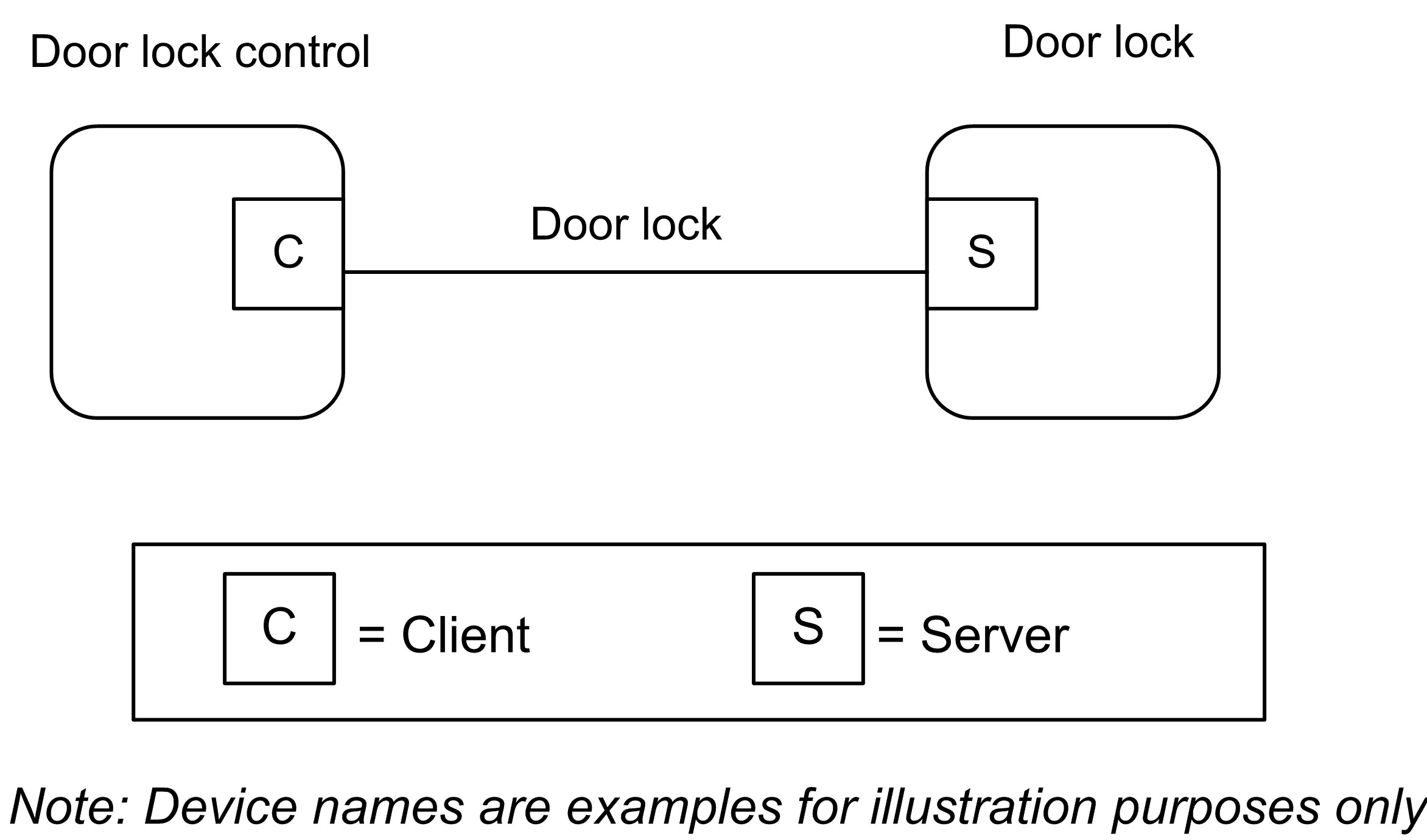
5.2. Door Lock
5.2.1. Overview
The door lock cluster provides an interface to a generic way to secure a door. The physical object that provides the locking functionality is abstracted from the cluster. The cluster has a small list of mandatory attributes and functions and a list of optional features.
5.2.1.1. Revision History
The global ClusterRevision attribute value SHALL be the highest revision number in the table below.
| Revision | Description |
|---|---|
|
1 |
mandatory global ClusterRevision attribute added; CCB 1811 1812 1821 |
|
2 |
CCB 2430 |
|
3 |
CCB 2629 2630 |
|
4 |
All Hubs changes and added feature map |
|
5 |
|
|
6 |
New data model format and notation. Added User features. General cleanup of functionality |
5.2.2. Features
This cluster SHALL support the Feature Map global attribute with these bits defined.
| Bit | Code | Feature | Conformance | Description |
|---|---|---|---|---|
|
0 |
PIN |
PIN Credential |
O |
Lock supports PIN credentials (via keypad, or over-the-air) |
|
1 |
RID |
RFID Credential |
O |
Lock supports RFID credentials |
|
2 |
FGP |
Finger Credentials |
P, O |
Lock supports finger related credentials (fingerprint, finger vein) |
|
3 |
LOG |
Logging |
O |
Lock supports local/on-lock logging when Events are not supported |
|
4 |
WDSCH |
Week Day Access Schedules |
O |
Lock supports week day user access schedules |
|
5 |
DPS |
Door Position Sensor |
O |
Lock supports a door position sensor that indicates door’s state |
|
6 |
FACE |
Face Credentials |
P, O |
Lock supports face related credentials (face, iris, retina) |
|
7 |
COTA |
Credential Over-the-Air Access |
O |
PIN codes over-the-air supported for lock/unlock operations |
|
8 |
USR |
User |
[ PIN | RID | FGP | FACE ] |
Lock supports the user commands and database |
|
9 |
NOT |
Notification |
O |
Operation and Programming Notifications |
|
10 |
YDSCH |
Year Day Access Schedules |
O |
Lock supports year day user access schedules |
|
11 |
HDSCH |
Holiday Schedules |
O |
Lock supports holiday schedules |
5.2.2.1. PIN Credential Feature
If the User Feature is also supported then any PIN Code stored in the lock SHALL be associated with a User.
A lock MAY support multiple credential types so if the User feature is supported the UserType, UserStatus and Schedules are all associated with a User index and not directly with a PIN index. A User index may have several credentials associated with it.
5.2.2.2. RFID Credential Feature
If the User Feature is also supported then any RFID credential stored in the lock SHALL be associated with a User.
A lock MAY support multiple credential types so if the User feature is supported the UserType, UserStatus and Schedules are all associated with a User index and not directly with a RFID index. A User Index may have several credentials associated with it.
5.2.2.3. Finger Credentials Feature
Currently the cluster only defines the metadata format for notifications when a fingerprint/ finger vein credential is used to access the lock and doesn’t describe how to create fingerprint/finger vein credentials. If the Users feature is also supported then the User that a fingerprint/finger vein is associated with can also have its UserType, UserStatus and Schedule modified.
A lock MAY support multiple credential types so if the User feature is supported the UserType, UserStatus and Schedules are all associated with a User index and not directly with a Finger index. A User Index may have several credentials associated with it.
5.2.2.4. Logging Feature
If Events are not supported the logging feature SHALL replace the Event reporting structure. If Events are supported the logging feature SHALL NOT be supported.
5.2.2.5. Week Day Access Schedules Feature
If the User feature is supported then Week Day Schedules are applied to a User and not a credential.
Week Day Schedules are used to restrict access to a specified time window on certain days of the week. The schedule is repeated each week. When a schedule is cleared this clears the access restrictions and grants unrestricted access to the user. The lock MAY automatically adjust the UserType when a schedule is created or cleared.
5.2.2.6. Door Position Sensor Feature
If this feature is supported this indicates that the lock has the ability to determine the position of the door which is separate from the state of the lock.
5.2.2.7. Face Credentials Feature
Currently the cluster only defines the metadata format for notifications when a face recognition, iris, or retina credential is used to access the lock and doesn’t describe how to create face recognition, iris, or retina credentials. If the Users feature is also supported then the User that a face recognition, iris, or retina credential is associated with can also have its UserType, UserStatus and Schedule modified.
A lock MAY support multiple credential types so if the User feature is supported the UserType, UserStatus and Schedules are all associated with a User and not directly with a credential.
5.2.2.8. Credential Over-the-Air Access Feature
If this feature is supported then the lock supports the ability to verify a credential provided in a lock/unlock command. Currently the cluster only supports providing the PIN credential to the lock/unlock commands. If this feature is supported then the PIN Credential feature SHALL also be supported.
5.2.2.9. User Feature
If the User Feature is supported then a lock employs a User database. A User within the User database is used to associate credentials and schedules to single user record within the lock. This also means the UserType and UserStatus fields are associated with a User and not a credential.
5.2.2.10. Notification Feature
This is a feature used before support of events. This feature supports notification commands and masks used to filter these notifications.
5.2.2.11. Year Day Access Schedules Feature
If the User feature is supported then Year Day Schedules are applied to a User and not a credential.
Year Day Schedules are used to restrict access to a specified date and time window. When a schedule is cleared this clears the access restrictions and grants unrestricted access to the user. The lock MAY automatically adjust the UserType when a schedule is created or cleared.
5.2.2.12. Holiday Schedules Feature
This feature is used to setup Holiday Schedule in the lock device. A Holiday Schedule sets a start and stop end date/time for the lock to use the specified operating mode set by the Holiday Schedule.
5.2.2.12.1. Recommended steps for creating a new User
It is RECOMMENDED that the Administrator query the door lock for what users already exist in its database to find an available UserIndex for creating a new User (see Get User Command ).
-
Use Set User Command with an available UserIndex to set the user record fields as applicable.
-
Use Set Credential Command with same UserIndex to add one or more credentials as applicable.
-
Use Set Week Day Schedule Command or Set Year Day Schedule Command with same UserIndex to add one or more schedule restrictions as applicable.
5.2.3. Attributes
| Id | Name | Type | Constraint | Quality | Default | Access | Conformance |
|---|---|---|---|---|---|---|---|
|
0x0000 |
LockState |
enum8 |
desc |
X P S |
R V |
M |
|
|
0x0001 |
LockType |
enum8 |
desc |
R V |
M |
||
|
0x0002 |
ActuatorEnabled |
bool |
all |
R V |
M |
||
|
0x0003 |
DoorState |
enum8 |
desc |
X P |
R V |
DPS |
|
|
0x0004 |
DoorOpenEvents |
uint32 |
all |
RW VM |
[DPS] |
||
|
0x0005 |
DoorClosedEvents |
uint32 |
all |
RW VM |
[DPS] |
||
|
0x0006 |
OpenPeriod |
uint16 |
all |
RW VM |
[DPS] |
||
|
0x0010 |
NumberOfLogRecordsSupported |
uint16 |
all |
F |
0 |
R V |
LOG |
|
0x0011 |
NumberOfTotalUsersSupported |
uint16 |
all |
F |
0 |
R V |
USR |
|
0x0012 |
NumberOfPINUsersSupported |
uint16 |
all |
F |
0 |
R V |
PIN |
|
0x0013 |
NumberOfRFIDUsersSupported |
uint16 |
all |
F |
0 |
R V |
RID |
|
0x0014 |
NumberOfWeekDaySchedulesSupportedPerUser |
uint8 |
all |
F |
0 |
R V |
WDSCH |
|
0x0015 |
NumberOfYearDaySchedulesSupportedPerUser |
uint8 |
all |
F |
0 |
R V |
YDSCH |
|
0x0016 |
NumberOfHolidaySchedulesSupported |
uint8 |
all |
F |
0 |
R V |
HDSCH |
|
0x0017 |
MaxPINCodeLength |
uint8 |
all |
F |
MS |
R V |
PIN |
|
0x0018 |
MinPINCodeLength |
uint8 |
all |
F |
MS |
R V |
PIN |
|
0x0019 |
MaxRFIDCodeLength |
uint8 |
all |
F |
MS |
R V |
RID |
|
0x001a |
MinRFIDCodeLength |
uint8 |
all |
F |
MS |
R V |
RID |
|
0x001b |
CredentialRulesSupport |
map8 |
all |
F |
1 |
R V |
USR |
|
0x001c |
NumberOfCredentialsSupportedPerUser |
uint8 |
all |
F |
0 |
R V |
USR |
|
0x0020 |
EnableLogging |
bool |
all |
P |
0 |
R[W] VA |
LOG |
|
0x0021 |
Language |
string |
max 3 |
P |
MS |
R[W] VM |
O |
|
0x0022 |
LEDSettings |
uint8 |
desc |
P |
0 |
R[W] VM |
O |
|
0x0023 |
AutoRelockTime |
uint32 |
all |
P |
MS |
R[W] VM |
O |
|
0x0024 |
SoundVolume |
uint8 |
desc |
P |
0 |
R[W] VM |
O |
|
0x0025 |
OperatingMode |
enum8 |
desc |
P |
0 |
R[W] VM |
M |
|
0x0026 |
SupportedOperatingModes |
map16 |
all |
F |
0xFFF6 |
R V |
M |
|
0x0027 |
DefaultConfigurationRegister |
map16 |
all |
P |
0 |
R V |
O |
|
0x0028 |
EnableLocalProgramming |
bool |
all |
P |
1 |
R[W] VA |
O |
|
0x0029 |
EnableOneTouchLocking |
bool |
all |
P |
0 |
RW VM |
O |
|
0x002a |
EnableInsideStatusLED |
bool |
all |
P |
0 |
RW VM |
O |
|
0x002b |
EnablePrivacyModeButton |
bool |
all |
P |
0 |
RW VM |
O |
|
0x002c |
LocalProgrammingFeatures |
map8 |
all |
P |
0 |
R[W] VA |
O |
|
0x0030 |
WrongCodeEntryLimit |
uint8 |
1 to 255 |
P |
MS |
R[W] VA |
PIN | RID |
|
0x0031 |
UserCodeTemporaryDisableTime |
uint8 |
1 to 255 |
P |
MS |
R[W] VA |
PIN | RID |
|
0x0032 |
SendPINOverTheAir |
bool |
all |
P |
0 |
R[W] VA |
[PIN] |
|
0x0033 |
RequirePINforRemoteOperation |
bool |
all |
P |
0 |
R[W] VA |
COTA & PIN |
|
0x0034 |
SecurityLevel |
0 |
D |
||||
|
0x0035 |
ExpiringUserTimeout |
uint16 |
1 to 2880 |
P |
MS |
R[W] VA |
[USR] |
|
0x0040 |
AlarmMask |
map16 |
all |
P |
0xFFFF |
RW VA |
O |
|
0x0041 |
KeypadOperationEventMask |
map16 |
all |
P |
0xFFFF |
RW VA |
[NOT & PIN] |
|
0x0042 |
RemoteOperationEventMask |
map16 |
all |
P |
0xFFFF |
RW VA |
[NOT] |
|
0x0043 |
ManualOperationEventMask |
map16 |
all |
P |
0xFFFF |
RW VA |
[NOT] |
|
0x0044 |
RFIDOperationEventMask |
map16 |
all |
P |
0xFFFF |
RW VA |
[NOT & RID] |
|
0x0045 |
KeypadProgrammingEventMask |
map16 |
all |
P |
0xFFFF |
RW VA |
[NOT & PIN] |
|
0x0046 |
RemoteProgrammingEventMask |
map16 |
all |
P |
0xFFFF |
RW VA |
[NOT] |
|
0x0047 |
RFIDProgrammingEventMask |
map16 |
all |
P |
0xFFFF |
RW VA |
[NOT & RID] |
AutoRelockTime, OperatingMode and SupportedOperatingModes represent mandatory fields that were previously not present or optional. Implementors should be aware that older devices may not implement them.
5.2.3.1. LockState Attribute
This attribute has the following possible values:
| Value | Name | Conformance | Description |
|---|---|---|---|
|
0 |
Not Fully Locked |
M |
Lock state is not fully locked |
|
1 |
Locked |
M |
Lock state is fully locked |
|
2 |
Unlocked |
M |
Lock state is fully unlocked |
The LockState Attribute may be NULL if the lock hardware does not currently know the status of the locking mechanism. For example, a lock may not know the LockState status after a power cycle until the first lock actuation is completed.
The Not Fully Locked value is used by a lock to indicate that the state of the lock is somewhere between Locked and Unlocked so it is only partially secured. For example, a deadbolt could be partially extended and not in a dead latched state.
If the Scenes server cluster is implemented on the same endpoint, the following extension field SHALL be added to the Scene Table:
-
LockState
When the LockState attribute is part of a Scene table, the attribute is treated as a writable command; that is, setting the LockState to lock will command the lock to lock, and setting the LockState to unlock will command the lock to unlock. Setting the LockState attribute to “not fully locked” is not supported. The Transition Time field in the Scene table will be treated as a delay before setting the LockState attribute; that is, it is possible to activate a scene with the lock actuation some seconds later.
Locks that do not have an actuation mechanism SHOULD not support the Scene table extension.
5.2.3.2. LockType Attribute
The LockType attribute is indicated by an enumeration:
| Value | Name | Description |
|---|---|---|
|
0 |
Dead bolt |
Physical lock type is dead bolt |
|
1 |
Magnetic |
Physical lock type is magnetic |
|
2 |
Other |
Physical lock type is other |
|
3 |
Mortise |
Physical lock type is mortise |
|
4 |
Rim |
Physical lock type is rim |
|
5 |
Latch Bolt |
Physical lock type is latch bolt |
|
6 |
Cylindrical Lock |
Physical lock type is cylindrical lock |
|
7 |
Tubular Lock |
Physical lock type is tubular lock |
|
8 |
Interconnected Lock |
Physical lock type is interconnected lock |
|
9 |
Dead Latch |
Physical lock type is dead latch |
|
10 |
Door Furniture |
Physical lock type is door furniture |
5.2.3.3. ActuatorEnabled Attribute
The ActuatorEnabled attribute indicates if the lock is currently able to (Enabled) or not able to (Disabled) process remote Lock, Unlock, or Unlock with Timeout commands.
This attribute has the following possible values:
| Boolean Value | Definition |
|---|---|
|
0 |
Disabled |
|
1 |
Enabled |
5.2.3.4. DoorState Attribute
The current door state as defined in DoorStateEnum .
This attribute SHALL be null only if an internal error prevents the retrieval of the current door state.
5.2.3.5. DoorOpenEvents Attribute
This attribute holds the number of door open events that have occurred since it was last zeroed.
5.2.3.6. DoorClosedEvents Attribute
This attribute holds the number of door closed events that have occurred since it was last zeroed.
5.2.3.7. OpenPeriod Attribute
This attribute holds the number of minutes the door has been open since the last time it transitioned from closed to open.
5.2.3.12. NumberOfWeekDaySchedulesSupportedPerUser Attribute
The number of configurable week day schedule supported per user.
5.2.3.13. NumberOfYearDaySchedulesSupportedPerUser Attribute
The number of configurable year day schedule supported per user.
5.2.3.14. NumberOfHolidaySchedulesSupported Attribute
The number of holiday schedules supported for the entire door lock device.
5.2.3.15. MaxPINCodeLength Attribute
An 8 bit value indicates the maximum length in bytes of a PIN Code on this device.
5.2.3.16. MinPINCodeLength Attribute
An 8 bit value indicates the minimum length in bytes of a PIN Code on this device.
5.2.3.17. MaxRFIDCodeLength Attribute
An 8 bit value indicates the maximum length in bytes of a RFID Code on this device. The value depends on the RFID code range specified by the manufacturer, if media anti-collision identifiers (UID) are used as RFID code, a value of 20 (equals 10 Byte ISO 14443A UID) is recommended.
5.2.3.18. MinRFIDCodeLength Attribute
An 8 bit value indicates the minimum length in bytes of a RFID Code on this device. The value depends on the RFID code range specified by the manufacturer, if media anti-collision identifiers (UID) are used as RFID code, a value of 8 (equals 4 Byte ISO 14443A UID) is recommended.
5.2.3.19. CredentialRulesSupport Attribute
This bitmap contains a bit for every value of CredentialRuleEnum supported on this device.
| Bit | CredentialRuleEnum | Definition |
|---|---|---|
|
0 |
Single |
Only one credential is required for lock operation |
|
1 |
Dual |
Any two credentials are required for lock operation |
|
2 |
Tri |
Any three credentials are required for lock operation |
5.2.3.20. NumberOfCredentialsSupportedPerUser Attribute
The number of credentials that could be assigned for each user.
Depending on the value of NumberOfRFIDUsersSupported and NumberOfPINUsersSupported it may not be possible to assign that number of credentials for a user.
For example, if the device supports only PIN and RFID credential types, NumberOfCredentialsSupportedPerUser is set to 10, NumberOfPINUsersSupported is set to 5 and NumberOfRFIDUsersSupported is set to 3, it will not be possible to actually assign 10 credentials for a user because maximum number of credentials in the database is 8.
5.2.3.21. EnableLogging Attribute
Enable/disable event logging. When event logging is enabled, all event messages are stored on the lock for retrieval. Logging events can be but not limited to Tamper Alarm, Lock, Unlock, AutoRelock, User Code Added, User Code Cleared, Schedule Added, and Schedule Cleared. For a full detail of all the possible alarms and events, please refer to the full list in the Alarm and Event Masks Attribute Set.
5.2.3.22. Language Attribute
Modifies the language for the on-screen or audible user interface using a 2-byte language code from ISO-639-1.
5.2.3.23. OperatingMode Attribute
The current operating mode of the lock (see OperatingModeEnum ).
5.2.3.24. SupportedOperatingModes Attribute
This bitmap contains all operating bits of the Operating Mode Attribute supported by the lock. All operating modes NOT supported by a lock SHALL be set to one. The value of the OperatingMode enumeration defines the related bit to be set, as shown below:
| Bit | OperatingMode | Conformance |
|---|---|---|
|
0 |
Normal |
M |
|
1 |
Vacation |
O |
|
2 |
Privacy |
O |
|
3 |
NoRemoteLockUnlock |
M |
|
4 |
Passage |
O |
5.2.3.25. LEDSettings Attribute
The settings for the LED support three different modes, shown below:
| Attribute Identifier | Definition |
|---|---|
|
0 |
Never use LED for signalization |
|
1 |
Use LED signalization except for access allowed events |
|
2 |
Use LED signalization for all events |
5.2.3.26. AutoRelockTime Attribute
The number of seconds to wait after unlocking a lock before it automatically locks again. 0=disabled. If set, unlock operations from any source will be timed. For one time unlock with timeout use the specific command.
5.2.3.27. SoundVolume Attribute
The sound volume on a door lock has four possible settings: silent, low, high and medium volumes, shown below:
| Attribute Identifier | Definition |
|---|---|
|
0 |
Silent Mode |
|
1 |
Low Volume |
|
2 |
High Volume |
|
3 |
Medium Volume |
5.2.3.28. DefaultConfigurationRegister Attribute
This attribute represents the default configurations as they are physically set on the device (example: hardware dip switch setting, etc…) and represents the default setting for some of the attributes within this cluster (for example: LED, Auto Lock, Sound Volume, and Operating Mode attributes).
This is a read-only attribute and is intended to allow clients to determine what changes MAY need to be made without having to query all the included attributes. It MAY be beneficial for the clients to know what the device’s original settings were in the event that the device needs to be restored to factory default settings.
If the Client device would like to query and modify the door lock server’s operating settings, it SHOULD send read and write attribute requests to the specific attributes.
For example, the Sound Volume attribute default value is Silent Mode. However, it is possible that the current Sound Volume is High Volume. Therefore, if the client wants to query/modify the current Sound Volume setting on the server, the client SHOULD read/write to the Sound Volume attribute.
This attribute has the following possible values:
| Bit | Description |
|---|---|
|
0 |
0 - Enable Local Programming Attribute default value is 0 (disabled) 1 - Enable Local Programming Attribute default value is 1 (enabled) |
|
1 |
0 –Keypad Interface default access is disabled 1 - Keypad Interface default access is enabled |
|
2 |
0 - Remote Interface default access is disabled 1 - Remote Interface default access is enabled |
|
5 |
0 – Sound Volume attribute default value is 0 (Silent Mode) 1 – Sound Volume attribute default value is equal to something other than 0 |
|
6 |
0 – Auto Relock Time attribute default value = 0 1 – Auto Relock Time attribute default value is equal to something other than 0 |
|
7 |
0 – Led Settings attribute default value = 0 1 – Led Settings attribute default value is equal to something other than 0 |
5.2.3.29. EnableLocalProgramming Attribute
Enable/disable local programming on the door lock of certain features (see LocalProgrammingFeatures attribute). If this value is set to TRUE then local programming is enabled on the door lock for all features. If it is set to FALSE then local programming is disabled on the door lock for those features whose bit is set to 0 in the LocalProgrammingFeatures attribute. Local programming SHALL be enabled by default.
5.2.3.30. EnableOneTouchLocking Attribute
Enable/disable the ability to lock the door lock with a single touch on the door lock.
5.2.3.31. EnableInsideStatusLED Attribute
Enable/disable an inside LED that allows the user to see at a glance if the door is locked.
5.2.3.32. EnablePrivacyModeButton Attribute
Enable/disable a button inside the door that is used to put the lock into privacy mode. When the lock is in privacy mode it cannot be manipulated from the outside.
5.2.3.33. LocalProgrammingFeatures Attribute
The local programming features that will be disabled when EnableLocalProgramming attribute is set to False. If a door lock doesn’t support disabling one aspect of local programming it SHALL return CONSTRAINT_ERROR during a write operation of this attribute. If the EnableLocalProgramming attribute is set to True then all local programming features SHALL be enabled regardless of the bits set to 0 in this attribute.
The features that can be disabled from local programming are defined in the following bitmap.
| Bit | Description |
|---|---|
|
0 |
0 - The ability to add Users/credentials/Schedules locally is disabled 1 - The ability to add Users/Credentials/Schedules locally is enabled |
|
1 |
0 - The ability to modify Users/credentials/Schedules locally is disabled 1 - The ability to modify Users/Credentials/Schedules locally is enabled |
|
2 |
0 - The ability to clear Users/credentials/Schedules locally is disabled 1 - The ability to clear Users/Credentials/Schedules locally is enabled |
|
3 |
0 - The ability to adjust lock settings locally is disabled 1 - The ability to adjust lock settings locally is enabled |
5.2.3.34. WrongCodeEntryLimit Attribute
The number of incorrect Pin codes or RFID presentment attempts a user is allowed to enter before the lock will enter a lockout state. The value of this attribute is compared to all failing forms of credential presentation, including Pin codes used in an Unlock Command when RequirePINforRemoteOperation is set to true. Valid range is 1-255 incorrect attempts. The lockout state will be for the duration of UserCodeTemporaryDisableTime. If the attribute accepts writes and an attempt to write the value 0 is made, the device SHALL respond with CONSTRAINT_ERROR.
The lock MAY reset the counter used to track incorrect credential presentations as required by internal logic, environmental events, or other reasons. The lock SHALL reset the counter if a valid credential is presented.
5.2.3.35. UserCodeTemporaryDisableTime Attribute
The number of seconds that the lock shuts down following wrong code entry. Valid range is 1-255 seconds. Device can shut down to lock user out for specified amount of time. (Makes it difficult to try and guess a PIN for the device.) If the attribute accepts writes and an attempt to write the attribute to 0 is made, the device SHALL respond with CONSTRAINT_ERROR.
5.2.3.36. SendPINOverTheAir Attribute
Boolean set to True if it is ok for the door lock server to send PINs over the air. This attribute determines the behavior of the server’s TX operation. If it is false, then it is not ok for the device to send PIN in any messages over the air.
The PIN field within any door lock cluster message SHALL keep the first octet unchanged and masks the actual code by replacing with 0xFF. For example (PIN "1234" ): If the attribute value is True, 0x04 0x31 0x32 0x33 0x34 SHALL be used in the PIN field in any door lock cluster message payload. If the attribute value is False, 0x04 0xFF 0xFF 0xFF 0xFF SHALL be used.
If the USR feature is supported by the device then this attribute SHALL NOT be supported.
5.2.3.37. RequirePINForRemoteOperation Attribute
Boolean set to True if the door lock server requires that an optional PINs be included in the payload of remote lock operation events like Lock, Unlock, Unlock with Timeout and Toggle in order to function.
5.2.3.38. ExpiringUserTimeout Attribute
Number of minutes a PIN, RFID, Fingerprint, or other credential associated with a user of type ExpiringUser SHALL remain valid after its first use before expiring. When the credential expires the UserStatus for the corresponding user record SHALL be set to OccupiedDisabled.
5.2.3.39. AlarmMask Attribute
This attribute is only supported if the Alarms cluster is on the same endpoint. The alarm mask is used to turn on/off alarms for particular functions. Alarms for an alarm group are enabled if the associated alarm mask bit is set. Each bit represents a group of alarms. Entire alarm groups can be turned on or off by setting or clearing the associated bit in the alarm mask.
This attribute has the following possible values:
This mask DOES NOT apply to the Events mechanism of this cluster.
| Alarm Code | Bit | Alarm Condition | Conformance |
|---|---|---|---|
|
0 |
0 |
Locking Mechanism Jammed |
M |
|
1 |
1 |
Lock Reset to Factory Defaults |
O |
|
2 |
2 |
Reserved |
O |
|
3 |
3 |
RF Module Power Cycled |
O |
|
4 |
4 |
Tamper Alarm - wrong code entry limit |
PIN | RID |
|
5 |
5 |
Tamper Alarm - front escutcheon removed from main |
O |
|
6 |
6 |
Forced Door Open under Door Locked Condition |
O |
5.2.3.40. KeypadOperationEventMask Attribute
Event mask used to turn on and off the transmission of keypad operation events. This mask DOES NOT apply to the storing of events in the event log. This mask only applies to the Operation Event Notification Command.
This attribute has the following possible values:
| Event Source | Operation Event Code | Attribute Bitmask | Event Description |
|---|---|---|---|
|
0 |
0 |
BIT(0) |
Unknown or manufacturer-specific keypad operation event |
|
0 |
1 |
BIT(1) |
Lock, source: keypad |
|
0 |
2 |
BIT(2) |
Unlock, source: keypad |
|
0 |
3 |
BIT(3) |
Lock, source: keypad, error: invalid PIN |
|
0 |
4 |
BIT(4) |
Lock, source: keypad, error: invalid schedule |
|
0 |
5 |
BIT(5) |
Unlock, source: keypad, error: invalid code |
|
0 |
6 |
BIT(6) |
Unlock, source: keypad, error: invalid schedule |
|
0 |
15 |
BIT(7) |
Non-Access User operation event, source keypad. |
This mask DOES NOT apply to the Events mechanism of this cluster.
5.2.3.41. RemoteOperationEventMask Attribute
Event mask used to turn on and off the transmission of remote operation events. This mask DOES NOT apply to the storing of events in the event log. This mask only applies to the Operation Event Notification Command.
This attribute has the following possible values:
| Event Source | Operation Event Code | Attribute Bitmask | Event Description |
|---|---|---|---|
|
1 |
0 |
BIT(0) |
Unknown or manufacturer-specific remote operation event |
|
1 |
1 |
BIT(1) |
Lock, source: remote |
|
1 |
2 |
BIT(2) |
Unlock, source: remote |
|
1 |
3 |
BIT(3) |
Lock, source: remote, error: invalid code |
|
1 |
4 |
BIT(4) |
Lock, source: remote, error: invalid schedule |
|
1 |
5 |
BIT(5) |
Unlock, source: remote, error: invalid code |
|
1 |
6 |
BIT(6) |
Unlock, source: remote, error: invalid schedule |
This mask DOES NOT apply to the Events mechanism of this cluster.
5.2.3.42. ManualOperationEventMask Attribute
Event mask used to turn on and off manual operation events. This mask DOES NOT apply to the storing of events in the event log. This mask only applies to the Operation Event Notification Command.
This attribute has the following possible values:
| Event Source | Operation Event Code | Attribute Bitmask | Event Description |
|---|---|---|---|
|
2 |
0 |
BIT(0) |
Unknown or manufacturer-specific manual operation event |
|
2 |
1 |
BIT(1) |
Thumbturn Lock |
|
2 |
2 |
BIT(2) |
Thumbturn Unlock |
|
2 |
7 |
BIT(3) |
One touch lock |
|
2 |
8 |
BIT(4) |
Key Lock |
|
2 |
9 |
BIT(5) |
Key Unlock |
|
2 |
10 |
BIT(6) |
Auto lock |
|
2 |
11 |
BIT(7) |
Schedule Lock |
|
2 |
12 |
BIT(8) |
Schedule Unlock |
|
2 |
13 |
BIT(9) |
Manual Lock (Key or Thumbturn) |
|
2 |
14 |
BIT(10) |
Manual Unlock (Key or Thumbturn) |
This mask DOES NOT apply to the Events mechanism of this cluster.
5.2.3.43. RFIDOperationEventMask Attribute
Event mask used to turn on and off RFID operation events. This mask DOES NOT apply to the storing of events in the event log. This mask only applies to the Operation Event Notification Command.
This attribute has the following possible values:
| Event Source | Operation Event Code | Attribute Bitmask | Event Description |
|---|---|---|---|
|
3 |
0 |
BIT(0) |
Unknown or manufacturer-specific keypad operation event |
|
3 |
1 |
BIT(1) |
Lock, source: RFID |
|
3 |
2 |
BIT(2) |
Unlock, source: RFID |
|
3 |
3 |
BIT(3) |
Lock, source: RFID, error: invalid RFID ID |
|
3 |
4 |
BIT(4) |
Lock, source: RFID, error: invalid schedule |
|
3 |
5 |
BIT(5) |
Unlock, source: RFID, error: invalid RFID ID |
|
3 |
6 |
BIT(6) |
Unlock, source: RFID, error: invalid schedule |
This mask DOES NOT apply to the Events mechanism of this cluster.
5.2.3.44. KeypadProgrammingEventMask Attribute
Event mask used to turn on and off keypad programming events. This mask DOES NOT apply to the storing of events in the event log. This mask only applies to the Programming Event Notification Command.
This attribute has the following possible values:
| Event Source | Program Event Code | Attribute Bitmask | Event Description |
|---|---|---|---|
|
0 |
0 |
BIT(0) |
Unknown or manufacturer-specific keypad programming event |
|
0 |
1 |
BIT(1) |
Programming PIN code changed, source: keypad User ID: programming user ID. PIN: default or programming PIN code if codes can be sent over the air per attribute. User type: default User Status: default |
|
0 |
2 |
BIT(2) |
PIN added, source: keypad User ID: user ID that was added. PIN: code that was added (if codes can be sent over the air per attribute.) User type: default or type added. User Status: default or status added. |
|
0 |
3 |
BIT(3) |
PIN cleared, source: keypad User ID: user ID that was cleared. PIN: code that was cleared (if codes can be sent over the air per attribute.) User type: default or type cleared. User Status: default or status cleared. |
|
0 |
4 |
BIT(4) |
PIN changed Source: keypad User ID: user ID that was changed PIN: code that was changed (if codes can be sent over the air per attribute.) User type: default or type changed. User Status: default or status changed. |
This mask DOES NOT apply to the Events mechanism of this cluster.
5.2.3.45. RemoteProgrammingEventMask Attribute
Event mask used to turn on and off remote programming events. This mask DOES NOT apply to the storing of events in the event log. This mask only applies to the Programming Event Notification Command.
This attribute has the following possible values:
| Event Source | Program Event Code | Attribute Bitmask | Event Description |
|---|---|---|---|
|
1 |
0 |
BIT(0) |
Unknown or manufacturer-specific remote programming event. |
|
1 |
2 |
BIT(2) |
PIN added, source remote Same as keypad source above |
|
1 |
3 |
BIT(3) |
PIN cleared, source remote Same as keypad source above. |
|
1 |
4 |
BIT(4) |
PIN changed Source remote Same as keypad source above |
|
1 |
5 |
BIT(5) |
RFID code added, Source remote |
|
1 |
6 |
BIT(6) |
RFID code cleared, Source remote |
This mask DOES NOT apply to the Events mechanism of this cluster.
5.2.3.46. RFIDProgrammingEventMask Attribute
Event mask used to turn on and off RFID programming events. This mask DOES NOT apply to the storing of events in the event log. This mask only applies to the Programming Event Notification Command.
This attribute has the following possible values:
| Event Source | Program Event Code | Attribute Bitmask | Event Description |
|---|---|---|---|
|
3 |
0 |
BIT(0) |
Unknown or manufacturer-specific keypad programming event |
|
3 |
5 |
BIT(5) |
ID Added, Source: RFID User ID: user ID that was added. ID: ID that was added (if codes can be sent over the air per attribute.) User Type: default or type added. User Status: default or status added. |
|
3 |
6 |
BIT(6) |
ID cleared, Source: RFID User ID: user ID that was cleared. ID: ID that was cleared (if codes can be sent over the air per attribute.) User Type: default or type cleared. User Status: default or status cleared. |
This mask DOES NOT apply to the Events mechanism of this cluster.
5.2.4. Commands
| Id | Name | Direction | Response | Access | Conformance |
|---|---|---|---|---|---|
|
0x00 |
Lock Door |
Client ⇒ Server |
Y |
T O |
M |
|
0x01 |
Unlock Door |
Client ⇒ Server |
Y |
T O |
M |
|
0x02 |
Toggle |
Client ⇒ Server |
Y |
T O |
X |
|
0x03 |
Unlock with Timeout |
Client ⇒ Server |
Y |
T O |
O |
|
0x04 |
Get Log Record |
Client ⇒ Server |
Get Log Record Response |
M |
LOG |
|
0x04 |
Get Log Record Response |
Server ⇒ Client |
N |
LOG |
|
|
0x05 |
Set PIN Code |
Client ⇒ Server |
Y |
T A |
!USR & PIN |
|
0x06 |
Get PIN Code |
Client ⇒ Server |
Get PIN Code Response |
A |
!USR & PIN |
|
0x06 |
Get PIN Code Response |
Server ⇒ Client |
N |
!USR & PIN |
|
|
0x07 |
Clear PIN Code |
Client ⇒ Server |
Y |
T A |
!USR & PIN |
|
0x08 |
Clear All PIN Codes |
Client ⇒ Server |
Y |
T A |
!USR & PIN |
|
0x09 |
Set User Status |
Client ⇒ Server |
Y |
A |
!USR & (PIN | RID | FGP) |
|
0x0a |
Get User Status |
Client ⇒ Server |
Get User Status Response |
A |
!USR & (PIN | RID | FGP) |
|
0x0a |
Get User Status Response |
Server ⇒ Client |
N |
!USR |
|
|
0x0b |
Set Week Day Schedule |
Client ⇒ Server |
Y |
A |
WDSCH |
|
0x0c |
Get Week Day Schedule |
Client ⇒ Server |
Get Week Day Schedule Response |
A |
WDSCH |
|
0x0c |
Get Week Day Schedule Response |
Server ⇒ Client |
N |
WDSCH |
|
|
0x0d |
Clear Week Day Schedule |
Client ⇒ Server |
Y |
A |
WDSCH |
|
0x0e |
Set Year Day Schedule |
Client ⇒ Server |
Y |
A |
YDSCH |
|
0x0f |
Get Year Day Schedule |
Client ⇒ Server |
Get Year Day Schedule Response |
A |
YDSCH |
|
0x0f |
Get Year Day Schedule Response |
Server ⇒ Client |
N |
YDSCH |
|
|
0x10 |
Clear Year Day Schedule |
Client ⇒ Server |
Y |
A |
YDSCH |
|
0x11 |
Set Holiday Schedule |
Client ⇒ Server |
Y |
A |
HDSCH |
|
0x12 |
Get Holiday Schedule |
Client ⇒ Server |
Get Holiday Schedule Response |
A |
HDSCH |
|
0x12 |
Get Holiday Schedule Response |
Server ⇒ Client |
N |
HDSCH |
|
|
0x13 |
Clear Holiday Schedule |
Client ⇒ Server |
Y |
A |
HDSCH |
|
0x14 |
Set User Type |
Client ⇒ Server |
Y |
A |
!USR & (PIN | RID | FGP) |
|
0x15 |
Get User Type |
Client ⇒ Server |
Get User Type Response |
A |
!USR & (PIN | RID | FGP) |
|
0x15 |
Get User Type Response |
Server ⇒ Client |
N |
!USR |
|
|
0x16 |
Set RFID Code |
Client ⇒ Server |
Y |
T A |
!USR & RID |
|
0x17 |
Get RFID Code |
Client ⇒ Server |
Get RFID Code Response |
A |
!USR & RID |
|
0x17 |
Get RFID Code Response |
Server ⇒ Client |
N |
!USR & RID |
|
|
0x18 |
Clear RFID Code |
Client ⇒ Server |
Y |
T A |
!USR & RID |
|
0x19 |
Clear All RFID Codes |
Client ⇒ Server |
Y |
T A |
!USR & RID |
|
0x1a |
Set User |
Client ⇒ Server |
Y |
T A |
USR |
|
0x1b |
Get User |
Client ⇒ Server |
Get User Response |
A |
USR |
|
0x1c |
Get User Response |
Server ⇒ Client |
N |
USR |
|
|
0x1d |
Clear User |
Client ⇒ Server |
Y |
T A |
USR |
|
0x20 |
Operating Event Notification |
Server ⇒ Client |
N |
[NOT] |
|
|
0x21 |
Programming Event Notification |
Server ⇒ Client |
N |
[NOT] |
|
|
0x22 |
Set Credential |
Client ⇒ Server |
Set Credential Response |
T A |
USR |
|
0x23 |
Set Credential Response |
Server ⇒ Client |
N |
USR |
|
|
0x24 |
Get Credential Status |
Client ⇒ Server |
Get Credential Status Response |
A |
USR |
|
0x25 |
Get Credential Status Response |
Server ⇒ Client |
N |
USR |
|
|
0x26 |
Clear Credential |
Client ⇒ Server |
Y |
T A |
USR |
5.2.4.1. Lock Door Command
This command causes the lock device to lock the door. This command includes an optional code for the lock. The door lock MAY require a PIN depending on the value of the [Require PIN for Remote Operation attribute].
| Id | Field | Type | Constraint | Quality | Default | Conformance |
|---|---|---|---|---|---|---|
|
0 |
PINCode PIN/RFID Code† |
octstr |
[COTA & PIN] |
† The PIN/RFID Code is an obsolete field name, use PINCode instead.
5.2.4.1.1. PINCode
If the RequirePINforRemoteOperation attribute is True then PINCode field SHALL be provided and the door lock SHALL NOT grant access if it is not provided.
If the PINCode field is provided, the door lock SHALL verify PINCode before granting access regardless of the value of RequirePINForRemoteOperation attribute.
When the PINCode field is provided an invalid PIN will count towards the WrongCodeEntryLimit and the UserCodeTemporaryDisableTime will be triggered if the WrongCodeEntryLimit is exceeded. The lock SHALL ignore any attempts to lock/unlock the door until the UserCodeTemporaryDisableTime expires.
5.2.4.2. Unlock Door Command
This command causes the lock device to unlock the door. This command includes an optional code for the lock. The door lock MAY require a code depending on the value of the [Require PIN for Remote Operation attribute].
Note: If the attribute AutoRelockTime is supported the lock will transition to the locked state when the auto relock time has expired.
| Id | Field | Type | Constraint | Quality | Default | Conformance |
|---|---|---|---|---|---|---|
|
0 |
PINCode PIN/RFID Code† |
octstr |
[COTA & PIN] |
† The PIN/RFID Code is an obsolete field name, use PINCode instead.
5.2.4.2.1. PINCode
See PINCode .
5.2.4.3. Unlock with Timeout Command
This command causes the lock device to unlock the door with a timeout parameter. After the time in seconds specified in the timeout field, the lock device will relock itself automatically. This timeout parameter is only temporary for this message transition and overrides the default relock time as specified in the AutoRelockTime attribute. If the door lock device is not capable of or does not want to support temporary Relock Timeout, it SHOULD NOT support this optional command.
| Id | Field | Type | Constraint | Quality | Default | Conformance |
|---|---|---|---|---|---|---|
|
0 |
Timeout |
uint16 |
M |
|||
|
1 |
PINCode PIN/RFID Code† |
octstr |
[COTA & PIN] |
† The PIN/RFID Code is an obsolete field name, use PINCode instead.
5.2.4.3.1. Timeout
The timeout in seconds to wait before relocking the door lock. This value is independent of the AutoRelockTime attribute value.
5.2.4.3.2. PINCode
See PINCode .
5.2.4.4. Get Log Record Command
Request a log record. Log number is between 1 – [Number of Log Records Supported attribute]. If log number 0 is requested then the most recent log entry is returned.
| Id | Field | Type | Constraint | Quality | Default | Conformance |
|---|---|---|---|---|---|---|
|
0 |
Log Index |
uint16 |
desc |
M |
Log record format: The log record format is defined in the description of the Get Log Record Response command.
5.2.4.5. Get Log Record Response Command
Returns the specified log record. If an invalid log entry ID was requested, it is set to 0 and the most recent log entry will be returned.
| Id | Field | Type | Constraint | Quality | Default | Conformance |
|---|---|---|---|---|---|---|
|
0 |
Log Entry ID |
uint16 |
desc |
M |
||
|
1 |
Timestamp |
epoch-s |
all |
M |
||
|
2 |
Event Type |
enum8 |
desc |
M |
||
|
3 |
Source (see Operation Event Sources) |
uint8 |
desc |
M |
||
|
4 |
Event ID/Alarm Code (see Operation Event Codes) |
uint8 |
desc |
M |
||
|
5 |
User ID |
uint16 |
desc |
M |
||
|
6 |
PIN |
octstr |
M |
Log Entry ID: the index into the log table where this log entry is stored. If the log entry requested is 0, the most recent log is returned with the appropriate log entry ID.
Timestamp: A timestamp for all events and alarms on the door lock in Epoch Time in Seconds with local time offset based on the local timezone and DST offset on the day of the event.
Event Type: Indicates the type of event that took place on the door lock.
0 = Operation
1 = Programming
2 = Alarm
Source: A source value where available sources are:
0x00 = Keypad
0x01 = Remote
0x02 = Manual
0x03 = RFID
0xFF = Indeterminate
If the Event type is 0x02 (Alarm) then the source SHOULD be but does not have to be 0xff (Indeterminate).
Event ID: A one-byte value indicating the type of event that took place on the door lock depending on the event code table provided for a given event type and source.
User ID: A two-byte value indicating the ID of the user who generated the event on the door lock if one is available. If none is available, 0xffff has to be used.
PIN / ID: A string indicating the PIN code or RFID code that was used to create the event on the door lock if one is available.
5.2.4.6. Set PIN Code Command
Set a PIN Code into the lock.
| Id | Field | Type | Constraint | Quality | Default | Conformance |
|---|---|---|---|---|---|---|
|
0 |
User ID |
uint16 |
desc |
M |
||
|
1 |
User Status |
uint8 |
X |
OccupiedEnabled |
M |
|
|
2 |
User Type |
enum8 |
X |
UnrestrictedUser |
M |
|
|
3 |
PIN |
octstr |
M |
User ID is between 0 - [# of PIN Users Supported attribute]. Only the values 1 (Occupied/Enabled) and 3 (Occupied/Disabled) are allowed for User Status.
Return status is a global status code or a cluster-specific status code from the DoorLockStatus table and SHALL be one of the following values:
| Name | Description |
|---|---|
|
SUCCESS |
Setting PIN code was successful. |
|
FAILURE |
Setting PIN code failed. |
|
CONSTRAINT_ERROR |
Setting PIN code failed because User ID requested was out of range. |
|
DUPLICATE |
Setting PIN code failed because it would create a duplicate PIN code. |
5.2.4.7. Get PIN Code Command
Retrieve a PIN Code. User ID is between 0 - [# of PIN Users Supported attribute].
| Id | Field | Type | Constraint | Quality | Default | Conformance |
|---|---|---|---|---|---|---|
|
0 |
User ID |
uint16 |
desc |
M |
5.2.4.8. Get PIN Code Response Command
Returns the PIN for the specified user ID.
| Id | Field | Type | Constraint | Quality | Default | Conformance |
|---|---|---|---|---|---|---|
|
0 |
User ID |
uint16 |
desc |
M |
||
|
1 |
User Status |
uint8 |
X |
Available |
M |
|
|
2 |
User Type |
enum8 |
X |
M |
||
|
3 |
PIN Code |
octstr |
X |
empty |
M |
If the requested User ID is valid and the Code doesn’t exist, Get RFID Code Response SHALL have the following format:
User ID = requested User ID
UserStatus = 0 (available)
UserType = 0xFF (not supported)
PIN Code = 0 (zero length)
If the requested User ID is invalid, send Default Response with an error status. The error status SHALL be equal to CONSTRAINT_ERROR when User_ID is less than the max number of users supported, and NOT_FOUND if greater than or equal to the max number of users supported.
5.2.4.9. Clear PIN Code Command
Clear a PIN code or all PIN codes.
| Id | Field | Type | Constraint | Quality | Default | Conformance |
|---|---|---|---|---|---|---|
|
0 |
PINSlotIndex User ID† |
uint16 |
1 to NumberOfPINUsersSupported, 0xFFFE |
M |
† The User ID is an obsolete field name, use PINSlotIndex instead.
For each PIN Code cleared whose user doesn’t have a RFID Code or other credential type, then corresponding user record’s UserStatus value SHALL be set to Available, and UserType value SHALL be set to UnrestrictedUser and all schedules SHALL be cleared.
5.2.4.10. Clear All PIN Codes Command
Clear out all PINs on the lock.
Note: On the server, the clear all PIN codes command SHOULD have the same effect as the Clear PIN Code command with respect to the setting of user status, user type and schedules.
5.2.4.11. Set User Status Command
Set the status of a user ID. User Status value of 0 is not allowed. In order to clear a user id, the Clear ID Command SHALL be used. For user status value please refer to User Status Value.
| Id | Field | Type | Constraint | Quality | Default | Conformance |
|---|---|---|---|---|---|---|
|
0 |
User ID |
uint16 |
desc |
M |
||
|
1 |
User Status |
uint8 |
M |
5.2.4.12. Get User Status Command
Get the status of a user.
| Id | Field | Type | Constraint | Quality | Default | Conformance |
|---|---|---|---|---|---|---|
|
0 |
User ID |
uint16 |
desc |
M |
5.2.4.13. Get User Status Response Command
Returns the user status for the specified user ID. If the requested User ID is invalid, the Status field SHALL be set to FAILURE. If the command is successful, the Status field SHALL be set to SUCCESS.
| Id | Field | Type | Constraint | Quality | Default | Conformance |
|---|---|---|---|---|---|---|
|
0 |
User ID |
uint16 |
desc |
M |
||
|
1 |
User Status |
enum8 |
M |
5.2.4.14. Set Week Day Schedule Command
Set a weekly repeating schedule for a specified user.
| Id | Field | Type | Constraint | Quality | Default | Conformance |
|---|---|---|---|---|---|---|
|
0 |
WeekDayIndex Schedule ID† |
uint8 |
1 to NumberOfWeekDaySchedulesSupportedPerUser |
M |
||
|
1 |
UserIndex User ID† |
uint16 |
1 to NumberOfTotalUsersSupported |
M |
||
|
2 |
DaysMask |
M |
||||
|
3 |
StartHour |
uint8 |
0 to 23 |
M |
||
|
4 |
StartMinute |
uint8 |
0 to 59 |
M |
||
|
5 |
EndHour |
uint8 |
0 to 23 |
M |
||
|
6 |
EndMinute |
uint8 |
0 to 59 |
M |
† The Schedule ID and User ID are obsolete field names, use WeekDayIndex and UserIndex instead, respectively.
The associated UserType MAY be changed to ScheduleRestrictedUser by the lock when a Week Day schedule is set.
Return status SHALL be one of the following values:
| Name | Description |
|---|---|
|
SUCCESS |
Setting Week Day schedule was successful. |
|
FAILURE |
Some unexpected internal error occurred setting Week Day schedule. |
|
INVALID_COMMAND |
One or more fields violates constraints or is invalid. Door lock is unable to set Week Day schedule for more than one day in DaysMask map (e.g. need to use separate schedules for each day). |
5.2.4.15. Get Week Day Schedule Command
Retrieve the specific weekly schedule for the specific user.
| Id | Field | Type | Constraint | Quality | Default | Conformance |
|---|---|---|---|---|---|---|
|
0 |
WeekDayIndex Schedule ID† |
uint8 |
1 to NumberOfWeekDaySchedulesSupportedPerUser |
M |
||
|
1 |
UserIndex User ID† |
uint16 |
1 to NumberOfTotalUsersSupported |
M |
† The Schedule ID and User ID are obsolete field names, use WeekDayIndex and UserIndex instead, respectively.
5.2.4.16. Get Week Day Schedule Response Command
Returns the weekly repeating schedule data for the specified schedule index.
| Id | Field | Type | Constraint | Quality | Default | Conformance |
|---|---|---|---|---|---|---|
|
0 |
WeekDayIndex Schedule ID† |
uint8 |
1 to NumberOfWeekDaySchedulesSupportedPerUser |
M |
||
|
1 |
UserIndex User ID† |
uint16 |
1 to NumberOfTotalUsersSupported |
M |
||
|
2 |
Status |
enum8 |
desc |
SUCCESS |
M |
|
|
3 |
DaysMask |
O |
||||
|
4 |
StartHour |
uint8 |
0 to 23 |
O |
||
|
5 |
StartMinute |
uint8 |
0 to 59 |
O |
||
|
6 |
EndHour |
uint8 |
0 to 23 |
O |
||
|
7 |
EndMinute |
uint8 |
0 to 59 |
O |
† The Schedule ID and User ID are obsolete field names, use WeekDayIndex and UserIndex instead, respectively.
5.2.4.16.1. Status
Status SHALL be one of the following values:
SUCCESS if both WeekDayIndex and UserIndex are valid and there is a corresponding schedule entry.
INVALID_COMMAND if either WeekDayIndex and/or UserIndex values are not within valid range
NOT_FOUND if both WeekDayIndex and UserIndex are within the valid range, however, there is not corresponding schedule entry found.
Only if the status is SUCCESS that other remaining fields are included. For other (error) status values, only the fields up to the status field SHALL be present.
5.2.4.17. Clear Week Day Schedule Command
Clear the specific weekly schedule or all weekly schedules for the specific user.
| Id | Field | Type | Constraint | Quality | Default | Conformance |
|---|---|---|---|---|---|---|
|
0 |
WeekDayIndex Schedule ID† |
uint8 |
1 to NumberOfWeekDaySchedulesSupportedPerUser, 0xFE |
M |
||
|
1 |
UserIndex User ID† |
uint16 |
1 to NumberOfTotalUsersSupported |
M |
† The Schedule ID and User ID are obsolete field names, use WeekDayIndex and UserIndex instead, respectively.
Return status SHALL be one of the following values:
| Name | Description |
|---|---|
|
SUCCESS |
Clearing Week Day schedule(s) was successful. |
|
FAILURE |
Some unexpected internal error occurred clearing Week Day schedule. |
|
INVALID_COMMAND |
One or more fields violates constraints or is invalid. |
5.2.4.18. Set Year Day Schedule Command
Set a time-specific schedule ID for a specified user.
| Id | Field | Type | Constraint | Quality | Default | Conformance |
|---|---|---|---|---|---|---|
|
0 |
YearDayIndex Schedule ID† |
uint8 |
1 to NumberOfYearDaySchedulesSupportedPerUser |
M |
||
|
1 |
UserIndex User ID† |
uint16 |
1 to NumberOfTotalUsersSupported |
M |
||
|
2 |
LocalStartTime |
epoch-s |
all |
M |
||
|
3 |
LocalEndTime |
epoch-s |
all |
M |
† The Schedule ID and User ID are obsolete field names, use YearDayIndex and UserIndex instead, respectively.
The associated UserType MAY be changed to ScheduleRestrictedUser by the lock when a Year Day schedule is set.
Return status SHALL be one of the following values:
| Name | Description |
|---|---|
|
SUCCESS |
Setting Year Day schedule was successful. |
|
FAILURE |
Some unexpected internal error occurred setting Year Day schedule. |
|
INVALID_COMMAND |
One or more fields violates constraints or is invalid. |
5.2.4.19. Get Year Day Schedule Command
Retrieve the specific year day schedule for the specific schedule and user indexes.
| Id | Field | Type | Constraint | Quality | Default | Conformance |
|---|---|---|---|---|---|---|
|
0 |
YearDayIndex Schedule ID† |
uint8 |
1 to NumberOfYearDaySchedulesSupportedPerUser |
M |
||
|
1 |
UserIndex User ID† |
uint16 |
1 to NumberOfTotalUsersSupported |
M |
† The Schedule ID and User ID are obsolete field names, use YearDayIndex and UserIndex instead, respectively.
5.2.4.20. Get Year Day Schedule Response Command
Returns the year day schedule data for the specified schedule and user indexes.
| Id | Field | Type | Constraint | Quality | Default | Conformance |
|---|---|---|---|---|---|---|
|
0 |
YearDayIndex Schedule ID† |
uint8 |
1 to NumberOfYearDaySchedulesSupportedPerUser |
M |
||
|
1 |
UserIndex User ID† |
uint16 |
1 to NumberOfTotalUsersSupported |
M |
||
|
2 |
Status |
enum8 |
desc |
SUCCESS |
M |
|
|
2 |
LocalStartTime |
epoch-s |
all |
X |
M |
|
|
3 |
LocalEndTime |
epoch-s |
all |
X |
M |
† The Schedule ID and User ID are obsolete field names, use YearDayIndex and UserIndex instead, respectively.
5.2.4.20.1. Status
Status SHALL be one of the following values:
SUCCESS if both YearDayIndex and UserIndex are valid and there is a corresponding schedule entry.
INVALID_COMMAND if either YearDayIndex and/or UserIndex values are not within valid range
NOT_FOUND if both YearDayIndex and UserIndex are within the valid range, however, there is not corresponding schedule entry found.
All fields SHALL be included irrespective of the value of the Status field. For error status values, the LocalStartTime and LocalEndTime fields SHALL be set to null.
5.2.4.20.2. LocalStartTime
The starting time for the Year Day schedule in Epoch Time in Seconds with local time offset based on the local timezone and DST offset on the day represented by the value. This SHALL be null if the schedule is not set for the YearDayIndex and UserIndex provided.
5.2.4.20.3. LocalEndTime
The ending time for the Year Day schedule in Epoch Time in Seconds with local time offset based on the local timezone and DST offset on the day represented by the value. LocalEndTime SHALL be greater than LocalStartTime. This SHALL be null if the schedule is not set for the YearDayIndex and UserIndex provided.
5.2.4.21. Clear Year Day Schedule Command
Clears the specific year day schedule or all year day schedules for the specific user.
| Id | Field | Type | Constraint | Quality | Default | Conformance |
|---|---|---|---|---|---|---|
|
0 |
YearDayIndex Schedule ID† |
uint8 |
1 to NumberOfYearDaySchedulesSupportedPerUser, 0xFE |
M |
||
|
1 |
UserIndex User ID† |
uint16 |
1 to NumberOfTotalUsersSupported |
M |
† The Schedule ID and User ID are obsolete field names, use YearDayIndex and UserIndex instead, respectively.
Return status SHALL be one of the following values:
| Name | Description |
|---|---|
|
SUCCESS |
Clearing Year Day schedule(s) was successful. |
|
FAILURE |
Some unexpected internal error occurred clearing Year Day schedule. |
|
INVALID_COMMAND |
One or more fields violates constraints or is invalid. |
5.2.4.22. Set Holiday Schedule Command
Set the holiday Schedule by specifying local start time and local end time with respect to any Lock Operating Mode.
| Id | Field | Type | Constraint | Quality | Default | Conformance |
|---|---|---|---|---|---|---|
|
0 |
HolidayIndex Holiday Schedule ID† |
uint8 |
1 to NumberOfHolidaySchedulesSupported |
M |
||
|
1 |
LocalStartTime |
epoch-s |
all |
M |
||
|
2 |
LocalEndTime |
epoch-s |
all |
M |
||
|
3 |
OperatingMode |
all |
M |
† The Holiday Schedule ID is an obsolete field name, use HolidayIndex instead.
Return status SHALL be one of the following values:
| Name | Description |
|---|---|
|
SUCCESS |
Setting Holiday schedule was successful. |
|
FAILURE |
Some unexpected internal error occurred setting Holiday schedule. |
|
INVALID_COMMAND |
One or more fields violates constraints or is invalid. |
5.2.4.22.1. LocalStartTime
The starting time for the Holiday Day schedule in Epoch Time in Seconds with local time offset based on the local timezone and DST offset on the day represented by the value.
5.2.4.23. Get Holiday Schedule Command
Get the holiday schedule for the specified index.
| Id | Field | Type | Constraint | Quality | Default | Conformance |
|---|---|---|---|---|---|---|
|
0 |
HolidayIndex Holiday Schedule ID† |
uint8 |
1 to NumberOfHolidaySchedulesSupported |
M |
† The Holiday Schedule ID is an obsolete field name, use HolidayIndex instead.
5.2.4.24. Get Holiday Schedule Response Command
Returns the Holiday Schedule Entry for the specified Holiday ID.
| Id | Field | Type | Constraint | Quality | Default | Conformance |
|---|---|---|---|---|---|---|
|
0 |
HolidayIndex Holiday Schedule ID† |
uint8 |
1 to NumberOfHolidaySchedulesSupported |
M |
||
|
1 |
Status |
enum8 |
desc |
SUCCESS |
M |
|
|
2 |
LocalStartTime |
epoch-s |
all |
X |
O |
|
|
3 |
Local End Time |
epoch-s |
all |
X |
O |
|
|
4 |
OperatingMode |
all |
X |
O |
† The Holiday Schedule ID is an obsolete field name, use HolidayIndex instead.
5.2.4.24.1. Status
Status SHALL be one of the following values:
FAILURE if the attribute NumberOfHolidaySchedulesSupported is zero.
SUCCESS if the HolidayIndex is valid and there is a corresponding schedule entry.
INVALID_COMMAND if the HolidayIndex is not within valid range
NOT_FOUND if the HolidayIndex is within the valid range, however, there is not corresponding schedule entry found.
Only if the status is SUCCESS that other remaining fields are included. For other (error) status values, only the fields up to the status field SHALL be present.
5.2.4.24.2. LocalStartTime
The starting time for the Holiday schedule in Epoch Time in Seconds with local time offset based on the local timezone and DST offset on the day represented by the value. This SHALL be null if the schedule is not set for the HolidayIndex provided.
5.2.4.24.3. LocalEndTime
The ending time for the Holiday schedule in Epoch Time in Seconds with local time offset based on the local timezone and DST offset on the day represented by the value. LocalEndTime SHALL be greater than LocalStartTime. This SHALL be null if the schedule is not set for the HolidayIndex provided.
5.2.4.25. Clear Holiday Schedule Command
Clears the holiday schedule or all holiday schedules.
| Id | Field | Type | Constraint | Quality | Default | Conformance |
|---|---|---|---|---|---|---|
|
0 |
HolidayIndex Holiday Schedule ID† |
uint8 |
1 to NumberOfHolidaySchedulesSupported, 0xFE |
M |
† The Holiday Schedule ID is an obsolete field name, use HolidayIndex instead.
5.2.4.26. Set User Type Command
Set the user type for a specified user.
For user type value please refer to User Type Value.
| Id | Field | Type | Constraint | Quality | Default | Conformance |
|---|---|---|---|---|---|---|
|
0 |
User ID |
uint16 |
desc |
M |
||
|
1 |
User Type |
enum8 |
M |
If UserType is currently YearDayScheduleUser, WeekDayScheduleUser, or ScheduleRestrictedUser and the new UserType is UnrestrictedUser then all existing Year Day and/or Week Day schedules SHALL be ignored or disabled (if this transition is supported by the door lock). If UserType is ScheduleRestrictedUser and the new UserType is ScheduleRestrictedUser then all existing Year Day and/or Week Day schedules SHALL be applied or enabled.
Return status SHALL be one of the following values:
| Name | Description |
|---|---|
|
SUCCESS |
Setting User Type was successful. |
|
FAILURE |
Some unexpected internal error occurred setting User Type. |
|
INVALID_COMMAND |
One or more fields violates constraints or is invalid. Door lock is unable to switch from restricted to unrestricted user (e.g. need to clear schedules to switch). |
5.2.4.27. Get User Type Command
Retrieve the user type for a specific user.
| Id | Field | Type | Constraint | Quality | Default | Conformance |
|---|---|---|---|---|---|---|
|
0 |
User ID |
uint16 |
desc |
M |
5.2.4.28. Get User Type Response Command
Returns the user type for the specified user ID. If the requested User ID is invalid, send Default Response with an error status equal to FAILURE.
| Id | Field | Type | Constraint | Quality | Default | Conformance |
|---|---|---|---|---|---|---|
|
0 |
User ID |
uint16 |
desc |
M |
||
|
1 |
User Type |
enum8 |
M |
5.2.4.29. Set RFID Code Command
Set an ID for RFID access into the lock.
| Id | Field | Type | Constraint | Quality | Default | Conformance |
|---|---|---|---|---|---|---|
|
0 |
User ID |
uint16 |
desc |
M |
||
|
1 |
User Status |
uint8 |
X |
OccupiedEnabled |
M |
|
|
2 |
User Type |
enum8 |
X |
UnrestrictedUser |
M |
|
|
3 |
RFID Code |
octstr |
M |
User ID : Between 0 - [# of RFID Users Supported attribute]. Only the values 1 (Occupied/Enabled) and 3 (Occupied/Disabled) are allowed for User Status.
User Status: Used to indicate what the status is for a specific user ID. The values are according to “Set PIN” while not all are supported.
| Value | User Status Byte | Conformance |
|---|---|---|
|
1 |
Occupied / Enabled (Access Given) |
M |
|
3 |
Occupied / Disabled |
M |
User Type: The values are the same as used for “Set PIN Code.”
Return status is a global status code or a cluster-specific status code from the DoorLockStatus table and SHALL be one of the following values:
| Name | Description |
|---|---|
|
SUCCESS |
Setting RFID code was successful. |
|
FAILURE |
Setting RFID code failed. |
|
CONSTRAINT_ERROR |
Setting RFID code failed because User ID requested was out of range. |
|
DUPLICATE |
Setting RFID code failed because it would create a duplicate RFID code. |
5.2.4.30. Get RFID Code Command
Retrieve an RFID code. User ID is between 0 - [# of RFID Users Supported attribute].
| Id | Field | Type | Constraint | Quality | Default | Conformance |
|---|---|---|---|---|---|---|
|
0 |
User ID |
uint16 |
desc |
M |
5.2.4.31. Get RFID Code Response Command
Returns the RFID code for the specified user ID.
| Id | Field | Type | Constraint | Quality | Default | Conformance |
|---|---|---|---|---|---|---|
|
0 |
User ID |
uint16 |
desc |
M |
||
|
1 |
User Status |
enum8 |
X |
Available |
M |
|
|
2 |
User Type |
enum8 |
X |
M |
||
|
3 |
RFID Code |
octstr |
X |
empty |
M |
If the requested User ID is valid and the Code doesn’t exist, Get RFID Code Response SHALL have the following format:
User ID = requested User ID
UserStatus = 0 (available)
UserType = 0xFF (not supported)
RFID Code = 0 (zero length)
If requested User ID is invalid, send Default Response with an error status. The error status shall be equal to CONSTRAINT_ERROR when User_ID is less than the max number of users supported, and NOT_FOUND if greater than or equal to the max number of users supported.
5.2.4.32. Clear RFID Code Command
Clear an RFID code or all RFID codes.
| Id | Field | Type | Constraint | Quality | Default | Conformance |
|---|---|---|---|---|---|---|
|
0 |
RFIDSlotIndex User ID† |
uint16 |
1 to NumberOfRFIDUsersSupported, 0xFFFE |
M |
† The User ID is an obsolete field name, use RFIDSlotIndex instead.
For each RFID Code cleared whose user doesn’t have a PIN Code or other credential type, then the corresponding user record’s UserStatus value SHALL be set to Available, and UserType value SHALL be set to UnrestrictedUser and all schedules SHALL be cleared.
5.2.4.33. Clear All RFID Codes Command
Clear out all RFIDs on the lock. If you clear all RFID codes and this user didn’t have a PIN code, the user status has to be set to "0 Available", the user type has to be set to the default value, and all schedules which are supported have to be set to the default values.
5.2.4.34. Set User Command
Set User into the lock.
| Id | Field | Type | Constraint | Quality | Default | Conformance |
|---|---|---|---|---|---|---|
|
0 |
OperationType |
Add, Modify |
M |
|||
|
1 |
UserIndex |
uint16 |
1 to NumberOfTotalUsersSupported |
M |
||
|
2 |
UserName |
string |
max 10 |
X |
empty |
M |
|
3 |
UserUniqueID |
uint32 |
all |
X |
0xFFFFFFFF |
M |
|
4 |
UserStatus |
OccupiedEnabled, OccupiedDisabled |
X |
OccupiedEnabled |
M |
|
|
5 |
UserType |
UnrestrictedUser, NonAccessUser, ForcedUser, DisposableUser, ExpiringUser, ScheduleRestrictedUser, RemoteOnlyUser |
X |
UnrestrictedUser |
M |
|
|
6 |
CredentialRule |
desc |
X |
Single |
M |
Fields used for different use cases:
| Use Case | Description |
|---|---|
|
Create a new user record |
CreatorFabricIndex and LastModifiedFabricIndex in the new user record SHALL be set to the accessing fabric index.
A
LockUserChange
event
SHALL
be
|
|
Modify an existing user record |
CreatorFabricIndex SHALL NOT be changed in the user record. LastModifiedFabricIndex in the new user record SHALL be set to the accessing fabric index.
A
LockUserChange
event
SHALL
be
|
Return status is a global status code or a cluster-specific status code from the DoorLockStatus table and SHALL be one of the following values:
-
SUCCESS, if setting User was successful.
-
FAILURE, if some unexpected internal error occurred setting User.
-
OCCUPIED, if OperationType is Add and UserIndex points to an occupied slot.
-
INVALID_COMMAND, if one or more fields violate constraints or are invalid or if OperationType is Modify and UserIndex points to an available slot.
5.2.4.34.1. UserName
A string to use as a human readable identifier for the user.
If UserName is null then:
-
If the OperationType is Add, the UserName in the resulting user record SHALL be set to an empty string.
-
If the OperationType is Modify, the UserName in the user record SHALL NOT be changed from the current value.
If UserName is not null, the UserName in the user record SHALL be set to the provided value.
5.2.4.34.2. UserUniqueID
A fabric assigned number to use for connecting this user to other users on other devices from the fabric’s perspective.
If UserUniqueID is null then:
-
If the OperationType is Add, the UserUniqueID in the resulting user record SHALL be set to default value specified above.
-
If the OperationType is Modify, the UserUniqueID in the user record SHALL NOT be changed from the current value.
If UserUniqueID is not null, the UserUniqueID in the user record SHALL be set to the provided value.
5.2.4.34.3. UserStatus
A UserStatus to assign to this user when created or modified.
If UserStatus is null then:
-
If the OperationType is Add, the UserStatus in the resulting user record SHALL be set to default value specified above.
-
If the OperationType is Modify, the UserStatus in the user record SHALL NOT be changed from the current value.
If UserStatus is not null, the UserStatus in the user record SHALL be set to the provided value.
5.2.4.34.4. UserType
A UserType to assign to this user when created or modified.
If UserType is null then:
-
If the OperationType is Add, the UserType in the resulting user record SHALL be set to default value specified above.
-
If the OperationType is Modify, the UserType in the user record SHALL NOT be changed from the current value.
If UserType is not null, the UserType in the user record SHALL be set to the provided value.
5.2.4.34.5. CredentialRule
The CredentialRule to use for this user.
The valid CredentialRule enumeration values depends on the bits in the CredentialRulesSupport map. Each bit in the map identifies a valid CredentialRule that can be used.
If CredentialRule is null then:
-
If the OperationType is Add, the CredentialRule in the resulting user record SHALL be set to default value specified above.
-
If the OperationType is Modify, the CredentialRule in the user record SHALL NOT be changed from the current value.
If CredentialRule is not null, the CredentialRule in the user record SHALL be set to the provided value.
5.2.4.35. Get User Command
Retrieve User.
| Id | Field | Type | Constraint | Quality | Default | Conformance |
|---|---|---|---|---|---|---|
|
0 |
UserIndex |
uint16 |
1 to NumberOfTotalUsersSupported |
M |
An InvokeResponse command SHALL be sent with an appropriate error (e.g. FAILURE, INVALID_COMMAND, etc.) as needed otherwise the Get User Response Command SHALL be sent implying a status of SUCCESS.
5.2.4.36. Get User Response Command
Returns the User for the specified UserIndex.
| Id | Field | Type | Constraint | Quality | Default | Conformance |
|---|---|---|---|---|---|---|
|
0 |
UserIndex |
uint16 |
1 to NumberOfTotalUsersSupported |
M |
||
|
1 |
UserName |
string |
max 10 |
X |
empty |
M |
|
2 |
UserUniqueID |
uint32 |
all |
X |
0 |
M |
|
3 |
UserStatus |
all |
X |
Available |
M |
|
|
4 |
UserType |
all |
X |
UnrestrictedUser |
M |
|
|
5 |
CredentialRule |
X |
Single |
M |
||
|
6 |
Credentials |
list[ CredentialStruct ] |
0 to NumberOfCredentialsSupportedPerUser |
X |
M |
|
|
7 |
CreatorFabricIndex |
fabric-idx |
all |
X |
M |
|
|
8 |
LastModifiedFabricIndex |
fabric-idx |
all |
X |
M |
|
|
9 |
NextUserIndex |
uint16 |
1 to NumberOfTotalUsersSupported |
X |
M |
If the requested UserIndex is valid and the UserStatus is Available for the requested UserIndex then UserName, UserUniqueID, UserStatus, UserType, CredentialRule, Credentials, CreatorFabricIndex, and LastModifiedFabricIndex SHALL all be null in the response.
5.2.4.36.1. CreatorFabricIndex
The
user’s
creator
fabric
index.
CreatorFabricIndex
SHALL
be
null
if
UserStatus
is
set
to
Available
or
when
the
creator
fabric
cannot
be
determined
(for
example,
when
user
was
created
outside
the
Interaction
Model)
and
SHALL
NOT
be
null
otherwise.
This
value
SHALL
be
set
to
0
if
the
original
creator
fabric
was
deleted.
5.2.4.36.2. LastModifiedFabricIndex
The
user’s
last
modifier
fabric
index.
LastModifiedFabricIndex
SHALL
be
null
if
UserStatus
is
set
to
Available
or
when
the
modifier
fabric
cannot
be
determined
(for
example,
when
user
was
modified
outside
the
Interaction
Model)
and
SHALL
NOT
be
null
otherwise.
This
value
SHALL
be
set
to
0
if
the
last
modifier
fabric
was
deleted.
5.2.4.36.3. NextUserIndex
The next occupied UserIndex in the database which is useful for quickly identifying occupied user slots in the database. This SHALL NOT be null if there is at least one occupied entry after the requested UserIndex in the User database and SHALL be null if there are no more occupied entries.
5.2.4.37. Clear User Command
Clears a User or all Users.
| Id | Field | Type | Constraint | Quality | Default | Conformance |
|---|---|---|---|---|---|---|
|
0 |
UserIndex |
uint16 |
1 to NumberOfTotalUsersSupported, 0xFFFE |
M |
For each User to clear, all associated credentials (e.g. PIN, RFID, fingerprint, etc.) SHALL be cleared and the User entry values SHALL be reset to their default values (e.g. UserStatus SHALL be Available, UserType SHALL be UnrestrictedUser) and all associated schedules SHALL be cleared.
A LockUserChange event with the provided UserIndex SHALL be generated after successfully clearing users.
5.2.4.38. Operation Event Notification Command
The door lock server sends out operation event notification when the event is triggered by the various event sources. The specific operation event will only be sent out if the associated bitmask is enabled in the various attributes in the Event Masks Attribute Set.
All events are optional.
| Id | Field | Type | Constraint | Quality | Default | Conformance |
|---|---|---|---|---|---|---|
|
0 |
Operation Event Source |
uint8 |
desc |
M |
||
|
1 |
Operation Event Code |
uint8 |
desc |
M |
||
|
2 |
User ID |
uint16 |
desc |
M |
||
|
3 |
PIN |
octstr |
M |
|||
|
4 |
LocalTime |
epoch-s |
all |
M |
||
|
5 |
Data |
string |
O |
5.2.4.38.1. Operation Event Sources
This field indicates where the event was triggered from.
| Value | Source |
|---|---|
|
0 |
Keypad |
|
1 |
Remote |
|
2 |
Manual |
|
3 |
RFID |
|
0xFF |
Indeterminate |
5.2.4.38.2. Operation Event Codes
The door lock optionally sends out notifications (if they are enabled) whenever there is a significant operational event on the lock. When combined with a source from the Event Source table above, the following operational event codes constitute an event on the door lock that can be both logged and sent to a bound device using the Operation Event Notification command.
Not all operation event codes are applicable to each of the event source. The following table marks each event code with “A” if the event code is applicable to the event source.
| Value | Name | Conformance | Applicable | |||
|---|---|---|---|---|---|---|
|
Keypad |
Remote |
Manual |
RFID |
|||
|
0 |
UnknownOrMfgSpecific |
O |
A |
A |
A |
A |
|
1 |
Lock |
O |
A |
A |
A |
A |
|
2 |
Unlock |
O |
A |
A |
A |
A |
|
3 |
LockFailureInvalidPINorRFID |
O |
A |
A |
A |
|
|
4 |
LockFailureInvalidSchedule |
O |
A |
A |
A |
|
|
5 |
UnlockFailureInvalidPINorRFID |
O |
A |
A |
A |
|
|
6 |
UnlockFailureInvalidSchedule |
O |
A |
A |
A |
|
|
7 |
OneTouchLock |
O |
A |
|||
|
8 |
KeyLock |
O |
A |
|||
|
9 |
KeyUnlock |
O |
A |
|||
|
10 |
AutoLock |
O |
A |
|||
|
11 |
ScheduleLock |
|
A |
|||
|
12 |
ScheduleUnlock |
|
A |
|||
|
13 |
Manual Lock (Key or Thumbturn) |
O |
A |
|||
|
14 |
Manual Unlock (Key or Thumbturn) |
O |
A |
|||
|
15 |
Non-access User Operation Event |
O |
A |
|||
5.2.4.38.5. LocalTime
The time when the event was triggered in Epoch Time in Seconds with local time offset based on the local timezone and DST offset on the day represented by the value. If time is not supported, the field SHALL be populated with default not used value 0xFFFFFFFF.
5.2.4.38.6. Data
The operation event notification command contains a variable string, which can be used to pass data associated with a particular event. Generally this field will be left empty. However, manufacturer can choose to use this field to store/display manufacturer-specific information.
5.2.4.38.7. Keypad Operation Event Notification
Keypad Operation Event Notification feature is enabled by setting the associated bitmasks in the [Keypad Operation Event Mask attribute].
5.2.4.38.8. Remote Operation Event Notification
Remote Operation Event Notification feature is enabled by setting the associated bitmasks in the [Remote Operation Event Mask attribute].
5.2.4.39. Programming Event Notification Command
The door lock server sends out a programming event notification whenever a programming event takes place on the door lock.
As with operational events, all programming events can be turned on and off by flipping bits in the associated event mask.
The programming event notification command includes an optional string of data that can be used by the manufacturer to pass some manufacturer-specific information if that is required.
| Id | Field | Type | Constraint | Quality | Default | Conformance |
|---|---|---|---|---|---|---|
|
0 |
Program Event Source |
uint8 |
desc |
M |
||
|
1 |
Program Event Code |
uint8 |
desc |
M |
||
|
2 |
User ID |
uint16 |
desc |
M |
||
|
3 |
PIN |
octstr |
M |
|||
|
4 |
User Type |
enum8 |
desc |
M |
||
|
5 |
User Status |
enum8 |
desc |
M |
||
|
6 |
LocalTime |
epoch-s |
all |
M |
||
|
7 |
Data |
string |
O |
5.2.4.39.1. Operation Event Sources
This field indicates where the event was triggered from.
| Value | Source |
|---|---|
|
0 |
Keypad |
|
1 |
Remote |
|
2 |
Reserved (Manual in Operation Event) |
|
3 |
RFID |
|
0xFF |
Indeterminate |
5.2.4.39.2. Programming Event Codes
The door lock optionally sends out notifications (if they are enabled) whenever there is a significant programming event on the lock. When combined with a source from the Event Source table above, the following programming event codes constitute an event on the door lock that can be both logged and sent to a bound device using the Programming Event Notification command.
Not all event codes are applicable to each of the event source. The following table marks each event code with “A” if the event code is applicable to the event source.
| Value | Programming Event Code | Keypad | Remote | RFID |
|---|---|---|---|---|
|
0 |
UnknownOrMfgSpecific |
A |
A |
A |
|
1 |
ProgrammingCodeChanged |
A |
||
|
2 |
PINCodeAdded |
A |
A |
|
|
3 |
PINCodeCleared |
A |
A |
|
|
4 |
PINCodeChanged |
A |
A |
|
|
5 |
RFIDCodeAdded |
A |
||
|
6 |
RFIDCodeCleared |
A |
5.2.4.39.7. LocalTime
The time when the event was triggered in Epoch Time in Seconds with local time offset based on the local timezone and DST offset on the day represented by the value. If time is not supported, the field SHALL be populated with default not used value 0xFFFFFFFF.
5.2.4.39.8. Data
The programming event notification command contains a variable string, which can be used to pass data associated with a particular event. Generally this field will be left empty. However, manufacturer can choose to use this field to store/display manufacturer-specific information.
5.2.4.39.9. Keypad Programming Event Notification
Keypad Programming Event Notification feature is enabled by setting the associated bitmasks in the [Keypad Programming Event Mask attribute].
5.2.4.40. Set Credential Command
Set a credential (e.g. PIN, RFID, Fingerprint, etc.) into the lock for a new user, existing user, or ProgrammingUser.
| Id | Field | Type | Constraint | Quality | Default | Conformance |
|---|---|---|---|---|---|---|
|
0 |
OperationType |
Add, Modify |
M |
|||
|
1 |
Credential |
M |
||||
|
2 |
CredentialData |
octstr |
desc |
M |
||
|
3 |
UserIndex |
uint16 |
1 to NumberOfTotalUsersSupported |
X |
M |
|
|
4 |
UserStatus |
OccupiedEnabled, OccupiedDisabled |
X |
OccupiedEnabled |
M |
|
|
5 |
UserType |
UnrestrictedUser, ProgrammingUser, NonAccessUser, ForcedUser, DisposableUser, ExpiringUser, RemoteOnlyUser |
X |
UnrestrictedUser |
M |
Fields used for different use cases:
| Use Case | Description |
|---|---|
|
Create a new credential and a new user record |
CreatorFabricIndex and LastModifiedFabricIndex in new user and credential records SHALL be set to the accessing fabric index.
A
LockUserChange
event
SHALL
be
|
|
Add a new credential to existing user record |
CreatorFabricIndex SHALL NOT be changed in the user record. LastModifiedFabricIndex in the user record SHALL be set to the accessing fabric index. CreatorFabricIndex and LastModifiedFabricIndex in the new credential record SHALL be set to the accessing fabric index.
A
LockUserChange
event
SHALL
be
|
|
Modify credential for an existing user record |
CreatorFabricIndex SHALL NOT be changed in user and credential records. LastModifiedFabricIndex in user and credential records SHALL be set to the accessing fabric index.
A
LockUserChange
event
SHALL
be
|
|
Modify credential for a Programming User |
CreatorFabricIndex SHALL NOT be changed in the credential record. LastModifiedFabricIndex in the credential record SHALL be set to the accessing fabric index.
A
LockUserChange
event
SHALL
be
|
5.2.4.40.2. Credential
A credential structure that contains the CredentialTypeEnum and the credential index (if applicable or 0 if not) to set.
5.2.4.40.3. CredentialData
The credential data to set for the credential being added or modified. The length of the credential data SHALL conform to the limits of the CredentialType specified in the Credential structure otherwise an INVALID_COMMAND status SHALL be returned in the Set Credential Response Command .
5.2.4.40.4. UserIndex
The user index to the user record that corresponds to the credential being added or modified. This SHALL be null if OperationType is add and a new credential and user is being added at the same time.
5.2.4.41. Set Credential Response Command
Returns the status for setting the specified credential.
| Id | Field | Type | Constraint | Quality | Default | Conformance |
|---|---|---|---|---|---|---|
|
0 |
Status |
status |
desc |
M |
||
|
1 |
UserIndex |
uint16 |
1 to NumberOfTotalUsersSupported |
X |
0 |
M |
|
2 |
NextCredentialIndex |
uint16 |
desc |
X |
O |
5.2.4.41.1. Status
Status comes from the DoorLockStatus table and SHALL be one of the following values:
-
SUCCESS, if setting user credential was successful.
-
FAILURE, if some unexpected internal error occurred setting user credential.
-
OCCUPIED, if OperationType is Add and CredentialIndex in Credential structure points to an occupied slot.
-
OCCUPIED, if OperationType is Modify and CredentialIndex in Credential structure does not match the CredentialIndex that is already associated with the provided UserIndex.
-
DUPLICATE, if CredentialData provided is a duplicate of another credential (e.g. duplicate PIN code).
-
RESOURCE_EXHAUSTED, if OperationType is Add and the user referred to by UserIndex already has NumberOfCredentialsSupportedPerUser credentials associated.
-
INVALID_COMMAND, if one or more fields violate constraints or are invalid or if OperationType is Modify and UserIndex points to an available slot.
5.2.4.41.2. UserIndex
The user index that was created with the new credential. If the status being returned is not success then this SHALL be null. This SHALL be null if OperationType was Modify; if the OperationType was Add and a new User was created this SHALL NOT be null and SHALL provide the UserIndex created. If the OperationType was Add and an existing User was associated with the new credential then this SHALL be null.
5.2.4.41.3. NextCredentialIndex
The next available index in the database for the credential type set, which is useful for quickly identifying available credential slots in the database. This SHALL NOT be null if there is at least one available entry after the requested credential index in the corresponding database and SHALL be null if there are no more available entries. The NextCredentialIndex reported SHALL NOT exceed the maximum number of credentials for a particular credential type.
5.2.4.42. Get Credential Status Command
Retrieve the status of a particular credential (e.g. PIN, RFID, Fingerprint, etc.) by index.
| Id | Field | Type | Constraint | Quality | Default | Conformance |
|---|---|---|---|---|---|---|
|
0 |
Credential |
M |
An InvokeResponse command SHALL be sent with an appropriate error (e.g. FAILURE, INVALID_COMMAND, etc.) as needed otherwise the Get Credential Status Response Command SHALL be sent implying a status of SUCCESS.
5.2.4.42.1. Credential
A credential structure that contains the CredentialTypeEnum and the credential index (if applicable or 0 if not) to retrieve the status for.
5.2.4.43. Get Credential Status Response Command
Returns the status for the specified credential.
| Id | Field | Type | Constraint | Quality | Default | Conformance |
|---|---|---|---|---|---|---|
|
0 |
CredentialExists |
bool |
all |
M |
||
|
1 |
UserIndex |
uint16 |
1 to NumberOfTotalUsersSupported |
X |
M |
|
|
2 |
CreatorFabricIndex |
fabric-idx |
all |
X |
M |
|
|
3 |
LastModifiedFabricIndex |
fabric-idx |
all |
X |
M |
|
|
4 |
NextCredentialIndex |
uint16 |
desc |
X |
O |
5.2.4.43.1. CredentialExists
A boolean value indicating the requested credential type and index exists and is populated for a given user index.
5.2.4.43.2. UserIndex
The credential’s corresponding user index value if the credential exists. If CredentialType requested was ProgrammingUser then UserIndex SHALL be null; otherwise, UserIndex SHALL be null if CredentialExists is set to False and SHALL NOT be null if CredentialExists is set to True.
5.2.4.43.3. CreatorFabricIndex
The
credential’s
creator
fabric
index.
CreatorFabricIndex
SHALL
be
null
if
CredentialExists
is
set
to
False
or
when
the
creator
fabric
cannot
be
determined
(for
example,
when
credential
was
created
outside
the
Interaction
Model)
and
SHALL
NOT
be
null
otherwise.
This
value
SHALL
be
set
to
0
if
the
original
creator
fabric
was
deleted.
5.2.4.43.4. LastModifiedFabricIndex
The
credential’s
last
modifier
fabric
index.
LastModifiedFabricIndex
SHALL
be
null
if
CredentialExists
is
set
to
False
or
when
the
modifier
fabric
cannot
be
determined
(for
example,
when
credential
was
modified
outside
the
Interaction
Model)
and
SHALL
NOT
be
null
otherwise.
This
value
SHALL
be
set
to
0
if
the
last
modifier
fabric
was
deleted.
5.2.4.43.5. NextCredentialIndex
The next occupied index in the database for the credential type requested, which is useful for quickly identifying occupied credential slots in the database. This SHALL NOT be null if there is at least one occupied entry after the requested credential index in the corresponding database and SHALL be null if there are no more occupied entries. The NextCredentialIndex reported SHALL NOT exceed the maximum number of credentials for a particular credential type.
5.2.4.44. Clear Credential Command
Clear one, one type, or all credentials except ProgrammingPIN credential.
| Id | Field | Type | Constraint | Quality | Default | Conformance |
|---|---|---|---|---|---|---|
|
0 |
Credential |
desc |
X |
M |
Fields used for different use cases:
| Use Case | Description |
|---|---|
|
Clear a single credential |
A
LockUserChange
event
SHALL
be
|
|
Clear all credentials of one type |
A
single
LockUserChange
event
SHALL
be
|
|
Clear all credentials of all types |
The ProgrammingPIN credential SHALL NOT be cleared.
|
For each credential cleared whose user doesn’t have another valid credential, the corresponding user record SHALL be reset back to default values and its UserStatus value SHALL be set to Available and UserType value SHALL be set to UnrestrictedUser and all schedules SHALL be cleared. In this case a LockUserChange event SHALL be generated for the user being cleared.
Return status SHALL be one of the following values:
| Name | Description |
|---|---|
|
SUCCESS |
Clearing credential(s) was successful. |
|
FAILURE |
Some unexpected internal error occurred clearing credential(s). |
|
INVALID_COMMAND |
One or more fields violate constraints or are invalid. |
5.2.4.44.1. Credential
A credential structure that contains the CredentialTypeEnum and the credential index (0xFFFE for all credentials or 0 if not applicable) to clear. This SHALL be null if clearing all credential types otherwise it SHALL NOT be null.
5.2.5. Events
This cluster SHALL support these events:
| Id | Name | Priority | Access | Conformance |
|---|---|---|---|---|
|
0 |
DoorLockAlarm |
CRITICAL |
V |
M |
|
1 |
DoorStateChange |
desc |
V |
DPS |
|
2 |
LockOperation |
desc |
V |
M |
|
3 |
LockOperationError |
desc |
V |
M |
|
4 |
LockUserChange |
INFO |
V |
USR |
The Events specified in this cluster are not intended to define the user experience. The events are only intended to define the metadata format used to notify any nodes that have subscribed for updates.
If the DoorState reported in the DoorStateChange event is not DoorClosed then the priority SHALL be CRITICAL; otherwise it MAY be INFO.
If the LockOperationType reported in the LockOperation event is Unlock or ForcedUserEvent then the priority SHALL be CRITICAL; otherwise it MAY be INFO.
If the OperationError reported in the LockOperationError event is DisabledUserDenied or the LockOperationType is Lock the priority SHALL be CRITICAL; otherwise it MAY be INFO.
5.2.5.1. DoorLockAlarm Event
The door lock cluster provides several alarms which can be sent when there is a critical state on the door lock. The alarms available for the door lock cluster are listed in the AlarmCodeEnum section below.
The data of this event SHALL contain the following information:
| Id | Field | Type | Constraint | Quality | Default | Conformance |
|---|---|---|---|---|---|---|
|
0 |
AlarmCode |
all |
M |
5.2.5.2. DoorStateChange Event
The door lock server sends out a DoorStateChange event when the door lock door state changes.
The data of this event SHALL contain the following information:
| Id | Field | Type | Constraint | Quality | Default | Conformance |
|---|---|---|---|---|---|---|
|
0 |
DoorState |
all |
M |
5.2.5.3. LockOperation Event
The door lock server sends out a LockOperation event when the event is triggered by the various lock operation sources.
The data of this event SHALL contain the following information:
| Id | Field | Type | Constraint | Quality | Default | Conformance |
|---|---|---|---|---|---|---|
|
0 |
LockOperationType |
all |
M |
|||
|
1 |
OperationSource |
all |
M |
|||
|
2 |
UserIndex |
uint16 |
all |
X |
M |
|
|
3 |
FabricIndex |
fabric-idx |
all |
X |
M |
|
|
4 |
SourceNode |
node-id |
all |
X |
M |
|
|
5 |
Credentials |
list[ CredentialStruct ] |
1 to NumberOfCredentialsSupportedPerUser |
X |
[USR] |
5.2.5.3.3. UserIndex
The lock UserIndex who performed the lock operation. This SHALL be null if there is no user index that can be determined for the given operation source. This SHALL NOT be null if a user index can be determined. In particular, this SHALL NOT be null if the operation was associated with a valid credential.
5.2.5.3.4. FabricIndex
The fabric index of the fabric that performed the lock operation. This SHALL be null if there is no fabric that can be determined for the given operation source. This SHALL NOT be null if the operation source is "Remote".
5.2.5.4. LockOperationError Event
The door lock server sends out a LockOperationError event when a lock operation fails for various reasons.
The data of this event SHALL contain the following information:
| Id | Field | Type | Constraint | Quality | Default | Conformance |
|---|---|---|---|---|---|---|
|
0 |
LockOperationType |
all |
M |
|||
|
1 |
OperationSource |
all |
M |
|||
|
2 |
OperationError |
all |
M |
|||
|
3 |
UserIndex |
uint16 |
all |
X |
M |
|
|
4 |
FabricIndex |
fabric-idx |
all |
X |
M |
|
|
5 |
SourceNode |
node-id |
all |
X |
M |
|
|
6 |
Credentials |
list[ CredentialStruct ] |
1 to NumberOfCredentialsSupportedPerUser |
X |
[USR] |
5.2.5.4.4. UserIndex
The lock UserIndex who performed the lock operation. This SHALL be null if there is no user id that can be determined for the given operation source.
5.2.5.4.5. FabricIndex
The fabric index of the fabric that performed the lock operation. This SHALL be null if there is no fabric that can be determined for the given operation source. This SHALL NOT be null if the operation source is "Remote".
5.2.5.5. LockUserChange Event
The door lock server sends out a LockUserChange event when a lock user, schedule, or credential change has occurred.
The data of this event SHALL contain the following information:
| Id | Field | Type | Constraint | Quality | Default | Conformance |
|---|---|---|---|---|---|---|
|
0 |
LockDataType |
all |
M |
|||
|
1 |
DataOperationType |
all |
M |
|||
|
2 |
OperationSource |
Unspecified, Keypad, Remote |
M |
|||
|
3 |
UserIndex |
uint16 |
all |
X |
M |
|
|
4 |
FabricIndex |
fabric-idx |
all |
X |
M |
|
|
5 |
SourceNode |
node-id |
all |
X |
M |
|
|
6 |
DataIndex |
uint16 |
all |
X |
M |
5.2.5.5.4. UserIndex
The lock UserIndex associated with the change (if any). This SHALL be null if there is no specific user associated with the data operation. This SHALL be 0xFFFE if all users are affected (e.g. Clear Users).
5.2.5.5.5. FabricIndex
The fabric index of the fabric that performed the change (if any). This SHALL be null if there is no fabric that can be determined to have caused the change. This SHALL NOT be null if the operation source is "Remote".
5.2.5.5.6. SourceNode
The Node ID that that performed the change (if any). The Node ID of the node that performed the change. This SHALL be null if there was no Node involved in the change. This SHALL NOT be null if the operation source is "Remote".
5.2.5.5.7. DataIndex
This is the index of the specific item that was changed (e.g. schedule, PIN, RFID, etc.) in the list of items identified by LockDataType. This SHALL be null if the LockDataType does not correspond to a list that can be indexed into (e.g. ProgrammingUser). This SHALL be 0xFFFE if all indices are affected (e.g. Clear PIN Code, Clear RFID Code, Clear Week Day Schedule, Clear Year Day Schedule, etc.).
5.2.6. Data Types
5.2.6.1. AlarmCodeEnum
The Alarm Code enum SHALL indicate the alarm type. The data type of the Alarm Code enum is derived from enum8.
| Value | Name | Conformance | Description |
|---|---|---|---|
|
0 |
LockJammed |
M |
Locking Mechanism Jammed |
|
1 |
LockFactoryReset |
O |
Lock Reset to Factory Defaults |
|
3 |
LockRadioPowerCycled |
O |
Lock Radio Power Cycled |
|
4 |
WrongCodeEntryLimit |
[USR] |
Tamper Alarm - wrong code entry limit |
|
5 |
FrontEsceutcheonRemoved |
O |
Tamper Alarm - front escutcheon removed from main |
|
6 |
DoorForcedOpen |
[DPS] |
Forced Door Open under Door Locked Condition |
|
7 |
DoorAjar |
[DPS] |
Door ajar |
|
8 |
ForcedUser |
[USR] |
Force User SOS alarm |
5.2.6.2. CredentialRuleEnum
The CredentialRule enum used in various commands SHALL indicate the credential rule that can be applied to a particular user. The data type of the CredentialRule enum is derived from enum8.
| Value | Name | Conformance | Definition |
|---|---|---|---|
|
0 |
Single |
USR |
Only one credential is required for lock operation |
|
1 |
Dual |
[USR] |
Any two credentials are required for lock operation |
|
2 |
Tri |
[USR] |
Any three credentials are required for lock operation |
5.2.6.3. CredentialStruct
The CredentialStruct is used in LockOperation event and Get User Record Response command and SHALL indicate the credential types and their corresponding indices (if any) for the event or user record.
| ID | Name | Type | Constraint | Quality | Default | Conformance |
|---|---|---|---|---|---|---|
|
0 |
CredentialType |
all |
M |
|||
|
1 |
CredentialIndex |
uint16 |
all |
0 |
M |
5.2.6.3.2. CredentialIndex
This is the index of the specific credential used to authorize the lock operation in the list of credentials identified by CredentialType (e.g. schedule, PIN, RFID, etc.). This SHALL be set to 0 if CredentialType is ProgrammingPIN or does not correspond to a list that can be indexed into.
5.2.6.4. CredentialTypeEnum
The Credential Type enum SHALL indicate the credential type. The data type of the Credential Type enum is derived from enum8.
| Value | Name | Conformance | Definition |
|---|---|---|---|
|
0 |
ProgrammingPIN |
O |
Programming PIN code credential type |
|
1 |
PIN |
PIN |
PIN code credential type |
|
2 |
RFID |
RID |
RFID identifier credential type |
|
3 |
Fingerprint |
FGP |
Fingerprint identifier credential type |
|
4 |
FingerVein |
FGP |
Finger vein identifier credential type |
|
5 |
Face |
FACE |
Face identifier credential type |
5.2.6.5. DataOperationTypeEnum
The DataOperationType enum SHALL indicate the data operation performed. The data type of the DataOperationType enum is derived from enum8.
| Value | Name | Conformance | Description |
|---|---|---|---|
|
0 |
Add |
M |
Data is being added or was added |
|
1 |
Clear |
M |
Data is being cleared or was cleared |
|
2 |
Modify |
M |
Data is being modified or was modified |
5.2.6.6. DaysMaskMap
The DaysMask field used in various commands and SHALL indicate the days of the week the Week Day schedule applies for. The data type of the DaysMask field is derived from map8.
| Bit | Description | Default | Conformance |
|---|---|---|---|
|
0 |
Sunday |
M |
|
|
1 |
Monday |
M |
|
|
2 |
Tuesday |
M |
|
|
3 |
Wednesday |
M |
|
|
4 |
Thursday |
M |
|
|
5 |
Friday |
M |
|
|
6 |
Saturday |
M |
5.2.6.7. DoorStateEnum
The DoorState enumeration SHALL indicate the current door state. The data type of the DoorState enum field is derived from enum8.
| Value | Name | Conformance | Description |
|---|---|---|---|
|
0 |
DoorOpen |
DPS |
Door state is open |
|
1 |
DoorClosed |
DPS |
Door state is closed |
|
2 |
DoorJammed |
[DPS] |
Door state is jammed |
|
3 |
DoorForcedOpen |
[DPS] |
Door state is currently forced open |
|
4 |
DoorUnspecifiedError |
[DPS] |
Door state is invalid for unspecified reason |
|
5 |
DoorAjar |
[DPS] |
Door state is ajar |
5.2.6.8. DoorLockStatus
The cluster-specific status codes for the Door Lock cluster are as follows:
| Value | Status Code | Description |
|---|---|---|
|
2 |
DUPLICATE |
Entry would cause a duplicate credential/ID. |
|
3 |
OCCUPIED |
Entry would replace an occupied slot. |
5.2.6.9. LockDataTypeEnum
The LockDataType enum SHALL indicate the data type that is being or has changed. The data type of the DataType enum is derived from enum8.
| Value | Name | Conformance | Description |
|---|---|---|---|
|
0 |
Unspecified |
O |
Unspecified or manufacturer specific lock user data added, cleared, or modified. |
|
1 |
ProgrammingCode |
O |
Lock programming PIN code was added, cleared, or modified. |
|
2 |
UserIndex |
M |
Lock user index was added, cleared, or modified. |
|
3 |
WeekDaySchedule |
WDSCH |
Lock user week day schedule was added, cleared, or modified. |
|
4 |
YearDaySchedule |
YDSCH |
Lock user year day schedule was added, cleared, or modified. |
|
5 |
HolidaySchedule |
HDSCH |
Lock holiday schedule was added, cleared, or modified. |
|
6 |
PIN |
PIN |
Lock user PIN code was added, cleared, or modified. |
|
7 |
RFID |
RID |
Lock user RFID code was added, cleared, or modified. |
|
8 |
Fingerprint |
FGP |
Lock user fingerprint was added, cleared, or modified. |
|
9 | FingerVein | FGP | Lock user finger-vein information was added, cleared, or modified. |
10 | Face | FACE | Lock user face information was added, cleared, or modified. |
5.2.6.10. LockOperationTypeEnum
The LockOperationType enumeration SHALL indicate the type of Lock operation performed. The data type of the LockOperationType enum field is derived from enum8.
| Value | Name | Conformance | Definition |
|---|---|---|---|
|
0 |
Lock |
M |
Lock operation |
|
1 |
Unlock |
M |
Unlock operation |
|
2 |
NonAccessUserEvent |
O |
Triggered by keypad entry for user with User Type set to Non Access User |
|
3 |
ForcedUserEvent |
O |
Triggered by using a user with UserType set to Forced User |
5.2.6.11. OperationErrorEnum
The OperationError enumeration SHALL indicate the error cause of the Lock/Unlock operation performed. The data type of the OperationError enum field is derived from enum8.
| Value | Name | Conformance | Definition |
|---|---|---|---|
|
0 |
Unspecified |
O |
Lock/unlock error caused by unknown or unspecified source |
|
1 |
InvalidCredential |
USR |
Lock/unlock error caused by invalid PIN, RFID, fingerprint or other credential |
|
2 |
DisabledUserDenied |
M |
Lock/unlock error caused by disabled USER or credential |
|
3 |
Restricted |
|
Lock/unlock error caused by schedule restriction |
|
4 |
InsufficientBattery |
O |
Lock/unlock error caused by insufficient battery power left to safely actuate the lock |
5.2.6.12. OperatingModeEnum
The OperatingMode enumeration SHALL indicate the lock operating mode. The data type of the OperatingMode enum field is derived from enum8.
The table below shows the operating mode and which interfaces are enabled, if supported, for each mode.
| Value | Name | Conformance | Interface Operational (Y = Yes; N = No) | ||
|---|---|---|---|---|---|
|
Keypad |
Remote |
RFID |
|||
|
0 |
Normal |
M |
Y |
Y |
Y |
|
1 |
Vacation |
O |
N |
Y |
N |
|
2 |
Privacy |
O |
N |
N |
N |
|
3 |
NoRemoteLockUnlock |
M |
Y |
N |
Y |
|
4 |
Passage |
O |
N/A |
N/A |
N/A |
Note: For modes that disable the remote interface, the door lock SHALL respond to Lock, Unlock, Toggle, and Unlock with Timeout commands with a response status Failure and not take the action requested by those commands. The door lock SHALL NOT disable the radio or otherwise unbind or leave the network. It SHALL still respond to all other commands and requests.
5.2.6.12.2. Vacation
Only remote interaction is enabled. The keypad SHALL only be operable by the master user.
5.2.6.12.3. Privacy
This mode is only possible if the door is locked. Manual unlocking changes the mode to Normal operating mode. All external interaction with the door lock is disabled. This mode is intended to be used so that users, presumably inside the property, will have control over the entrance.
5.2.6.13. OperationSourceEnum
The OperationSource enumeration SHALL indicate the source of the Lock/Unlock operation performed. The data type of the OperationSource enum field is derived from enum8.
| Value | Name | Conformance | Definition |
|---|---|---|---|
|
0 |
Unspecified |
O |
Lock/unlock operation came from unspecified source |
|
1 |
Manual |
O |
Lock/unlock operation came from manual operation (key, thumbturn, handle, etc). |
|
2 |
ProprietaryRemote |
O |
Lock/unlock operation came from prioretary remote source (e.g. vendor app/cloud) |
|
3 |
Keypad |
O |
Lock/unlock operation came from keypad |
|
4 |
Auto |
O |
Lock/unlock operation came from lock automatically (e.g. relock timer) |
|
5 |
Button |
O |
Lock/unlock operation came from lock button (e.g. one touch or button) |
|
6 |
Schedule |
HDSCH |
Lock/unlock operation came from lock due to a schedule |
|
7 |
Remote |
M |
Lock/unlock operation came from remote node |
|
8 |
RFID |
RID |
Lock/unlock operation came from RFID card |
|
9 |
Biometric |
[USR] |
Lock/unlock operation came from biometric source (e.g. face, fingerprint/fingervein) |
5.2.6.14. PIN/RFID Code Format
The
PIN/RFID
codes
defined
in
this
specification
are
all
in
Octet
String
format.
The
first
octet
in
the
string
specifies
the
number
of
octets
contained
in
the
remaining
of
the
data
field
not
including
itself.
strings.
All value in the PIN/RFID code SHALL be ASCII encoded regardless if the PIN/RFID codes are number or characters. For example, code of “1, 2, 3, 4” SHALL be represented as 0x31, 0x32, 0x33, 0x34.
5.2.6.15. UserStatusEnum
The UserStatus enum used in various commands SHALL indicate what the status is for a specific user ID.
| Enum | Description | Conformance |
|---|---|---|
|
0 |
Available |
M |
|
1 |
OccupiedEnabled |
M |
|
3 |
OccupiedDisabled |
O |
5.2.6.16. UserTypeEnum
The UserType enum used in various commands SHALL indicate what the type is for a specific user ID.
| Enum | Description | Conformance |
|---|---|---|
|
0 |
UnrestrictedUser |
M |
|
1 |
YearDayScheduleUser |
O |
|
2 |
WeekDayScheduleUser |
O |
|
3 |
ProgrammingUser |
O |
|
4 |
NonAccessUser |
O |
|
5 |
ForcedUser |
[USR] |
|
6 |
DisposableUser |
[USR] |
|
7 |
ExpiringUser |
[USR] |
|
8 |
ScheduleRestrictedUser |
|
|
|
RemoteOnlyUser |
USR & COTA & PIN |
5.2.6.16.1. UnrestrictedUser
User has access 24/7 provided proper PIN or RFID is supplied (e.g., owner).
5.2.6.16.2. YearDayScheduleUser
User has ability to open lock within a specific time period (e.g., guest).
5.2.6.16.3. WeekDayScheduleUser
User has ability to open lock based on specific time period within a reoccurring weekly schedule (e.g., cleaning worker).
5.2.6.16.4. ProgrammingUser
User has ability to both program and operate the door lock. This user can manage the users and user schedules. In all other respects this user matches the unrestricted (default) user. ProgrammingUser is the only user that can disable the user interface (keypad, remote, etc…).
5.2.6.16.5. NonAccessUser
User is recognized by the lock but does not have the ability to open the lock. This user will only cause the lock to generate the appropriate event notification to any bound devices.
5.2.6.16.6. ForcedUser
User has ability to open lock but a ForcedUser LockOperationType and ForcedUser silent alarm will be emitted to allow a notified Node to alert emergency services or contacts on the user account when used.
5.2.6.16.7. DisposableUser
User has ability to open lock once after which the lock SHALL change the corresponding user record UserStatus value to OccupiedDisabled automatically.
5.2.6.16.8. ExpiringUser
User has ability to open lock for ExpiringUserTimeout attribute minutes after the first use of the PIN code, RFID code, Fingerprint, or other credential. After ExpiringUserTimeout minutes the corresponding user record UserStatus value SHALL be set to OccupiedDisabled automatically by the lock. The lock SHALL persist the timeout across reboots such that the ExpiringUserTimeout is honored.
5.2.6.16.10. RemoteOnlyUser
User access and PIN code is restricted to remote lock/unlock commands only. This type of user might be useful for regular delivery services or voice assistant unlocking operations to prevent a PIN code credential created for them from being used at the keypad. The PIN code credential would only be provided over-the-air for the lock/unlock commands.
5.3. Window Covering
The window covering cluster provides an interface for controlling and adjusting automatic window coverings such as drapery motors, automatic shades, curtains and blinds.
5.3.1. Revision History
The global ClusterRevision attribute value SHALL be the highest revision number in the table below.
| Rev | Description |
|---|---|
|
1 |
mandatory global ClusterRevision attribute added; CCB 1994 1995 1996 1997 2086 2094 2095 2096 2097 |
|
2 |
CCB 2328 |
|
3 |
CCB 2477 2555 2845 3028 |
|
4 |
All Hubs changes with FeatureMap & OperationalStatus attribute |
|
5 |
New data model format and notation. Created plus clarified Position Aware and Absolute Position features. General cleanup of functionality. |
5.3.2. Classification
| Hierarchy | Role | PICS Code | Primary Transaction |
|---|---|---|---|
|
Base |
Application |
WNCV |
Type 1 (client to server) |
5.3.4. Features
This cluster SHALL support the FeatureMap bitmap attribute as defined below.
| Bit | Code |
|
|
|
|---|---|---|---|---|
|
0 |
LF |
Lift * |
|
Lift Control and behavior for lifting/sliding window coverings |
|
1 |
TL |
Tilt * |
|
Tilt Control and behavior for tilting window coverings |
|
2 |
PA_LF |
|
|
Position Aware lift control is supported. |
|
3 |
ABS |
|
|
Absolute positioning is supported. |
|
4 |
PA_TL |
|
|
Position Aware tilt control is supported. |
* At least one of the Lift and Tilt features SHALL be supported.
Due to backward compatibility reasons this feature map SHALL match the advertised Type Attribute Supported Features.
5.3.4.1. Lift
The Lift feature applies to window coverings that lift up and down (ex: for a rollershade, Up and Down is Lift Open and Close) or slide left to right (ex: for a sliding curtain, Left and Right is Lift Open and Close).
5.3.4.3. Position Aware
Relative positioning with percent100ths (min step 0.01%) attribute is mandatory, E.g Max 10000 equals 100.00% and relative positioning with percent (min step 1%) attribute is for backward compatibility.
The CurrentPosition attributes SHALL always reflects the physical position of an actuator and the TargetPosition attribute SHALL reflect the requested position of an actuator once a positioning command is received.
5.3.4.4. Absolute Position
The percentage attributes SHALL indicate the position as a percentage between the InstalledOpenLimits and InstalledClosedLimits attributes of the window covering starting at the open (0.00%).
As a general rule, absolute positioning (in centimeters or tenth of a degrees) SHOULD NOT be supported for new implementations.
5.3.5. Attributes
| ID | Name | Unit | Type | Constraint | Quality | Default | Access | Conformance |
|---|---|---|---|---|---|---|---|---|
|
0x0000 |
Type |
enum8 |
desc |
F |
0 |
R V |
M |
|
|
0x0001 |
PhysicalClosedLimitLift |
cm |
uint16 |
all |
F |
0 |
R V |
[LF & PA_LF & ABS] |
|
0x0002 |
PhysicalClosedLimitTilt |
0.1° |
uint16 |
all |
F |
0 |
R V |
[TL & PA_TL & ABS] |
|
0x0003 |
CurrentPositionLift 1 |
cm |
uint16 |
InstalledOpenLimitLift to InstalledClosedLimitLift |
XN |
null |
R V |
[LF & PA_LF & ABS] |
|
0x0004 |
CurrentPositionTilt 1 |
0.1° |
uint16 |
InstalledOpenLimitTilt to InstalledClosedLimitTilt |
XN |
null |
R V |
[TL & PA_TL & ABS] |
|
0x0005 |
NumberOfActuationsLift |
# |
uint16 |
all |
N |
0 |
R V |
[LF] |
|
0x0006 |
NumberOfActuationsTilt |
# |
uint16 |
all |
N |
0 |
R V |
[TL] |
|
0x0007 |
ConfigStatus |
map8 |
desc |
N |
desc |
R V |
M |
|
|
0x0008 |
CurrentPositionLiftPercentage 1 |
1% |
percent |
0 to 100 |
XNSP |
null |
R V |
[LF & PA_LF] |
|
0x0009 |
CurrentPositionTiltPercentage 1 |
1% |
percent |
0 to 100 |
XNSP |
null |
R V |
[TL & PA_TL] |
|
0x000a |
OperationalStatus |
map8 |
00xx xxxx |
P |
0 |
R V |
M |
|
|
0x000b |
TargetPositionLiftPercent100ths 2 |
0.01% |
percent100ths |
0 to 10000 |
XSP |
null |
R V |
LF & PA_LF |
|
0x000c |
TargetPositionTiltPercent100ths 2 |
0.01% |
percent100ths |
0 to 10000 |
XSP |
null |
R V |
TL & PA_TL |
|
0x000d |
EndProductType |
enum8 |
desc |
F |
0 |
R V |
M |
|
|
0x000e |
CurrentPositionLiftPercent100ths 1 |
0.01% |
percent100ths |
0 to 10000 |
XNP |
null |
R V |
LF & PA_LF |
|
0x000f |
CurrentPositionTiltPercent100ths 1 |
0.01% |
percent100ths |
0 to 10000 |
XNP |
null |
R V |
TL & PA_TL |
|
0x0010 |
InstalledOpenLimitLift |
cm |
uint16 |
0 to 65534 |
N |
0 |
R V |
LF & PA_LF & ABS |
|
0x0011 |
InstalledClosedLimitLift |
cm |
uint16 |
0 to 65534 |
N |
65534 |
R V |
LF & PA_LF & ABS |
|
0x0012 |
InstalledOpenLimitTilt |
0.1° |
uint16 |
0 to 65534 |
N |
0 |
R V |
TL & PA_TL & ABS |
|
0x0013 |
InstalledClosedLimitTilt |
0.1° |
uint16 |
0 to 65534 |
N |
65534 |
R V |
TL & PA_TL & ABS |
|
0x0014 |
VelocityLift |
D |
||||||
|
0x0015 |
AccelerationTimeLift |
D |
||||||
|
0x0016 |
DecelerationTimeLift |
D |
||||||
|
0x0017 |
Mode |
- |
map8 |
0000 xxxx |
N |
0 |
RW VM |
M |
|
0x0018 |
IntermediateSetpointsLift |
D |
||||||
|
0x0019 |
IntermediateSetpointsTilt |
D |
||||||
|
0x001a |
SafetyStatus |
map16 |
desc |
P |
0 |
R V |
O |
For attributes designated with "S" in the Quality column, please see Scene Table Extensions .
|
Note
|
Nullable
positions
1 - The null value indicates that the current position is unknown, e.g. calibration is needed. 2 - The null value indicates that the value is unavailable, e.g. no target position has been set. |
5.3.5.1. Type Attribute
The Type attribute identifies the type of window covering being controlled by this endpoint and SHALL be set to one of the non-reserved values in the table below.
| Value | Type | Supported Features |
|---|---|---|
|
0x00 |
Rollershade |
Lift |
|
0x01 |
Rollershade - 2 Motor |
Lift |
|
0x02 |
Rollershade - Exterior |
Lift |
|
0x03 |
Rollershade - Exterior - 2 Motor |
Lift |
|
0x04 |
Drapery (curtain) |
Lift |
|
0x05 |
Awning |
Lift |
|
0x06 |
Shutter |
Tilt, Lift |
|
0x07 |
Tilt Blind - Tilt Only |
Tilt |
|
0x08 |
Tilt Blind - Lift & Tilt |
Lift, Tilt |
|
0x09 |
Projector Screen |
Lift |
|
0xFF |
Unknown |
5.3.5.2. PhysicalClosedLimitLift Attribute
The PhysicalClosedLimitLift attribute identifies the maximum possible encoder position possible (in centimeters) to position the height of the window covering Lift.
5.3.5.3. PhysicalClosedLimitTilt Attribute
The PhysicalClosedLimitTilt attribute identifies the maximum possible encoder position possible (tenth of a degrees) to position the angle of the window covering Tilt.
5.3.5.4. CurrentPositionLift Attribute
The CurrentPositionLift attribute identifies the actual Lift position (in centimeters) of the window covering from the fully-open position.
5.3.5.5. CurrentPositionTilt Attribute
The CurrentPositionTilt attribute identifies the actual Tilt position (in tenth of an degree) of the window covering from the fully-open position.
5.3.5.6. NumberOfActuationsLift Attribute
The NumberOfActuationsLift attribute identifies the total number of lift/slide actuations applied to the Window Covering since the device was installed.
5.3.5.7. NumberOfActuationsTilt Attribute
The NumberOfActuationsTilt attribute identifies the total number of tilt actuations applied to the Window Covering since the device was installed.
5.3.5.8. ConfigStatus Attribute
The ConfigStatus attribute makes configuration and status information available. To change settings, devices SHALL write to the Mode attribute of the Window Covering Settings Attribute Set. The behavior causing the setting or clearing of each bit is vendor specific. See table below for details on each bit.
| Bit | Meaning | Description | M |
|---|---|---|---|
|
0 |
1 = Operational |
Operational: This status bit defines if the Window Covering is operational. The SafetyStatus & Mode attributes might affect this bit |
M |
|
1 |
Reserved |
deprecated |
D |
|
2 |
1 = Lift movement is reversed |
Reversal: This status bit identifies if the directions of the lift/slide movements have been reversed in order for commands (e.g: Open, Close, GoTos) to match the physical installation conditions This bit can be adjusted by setting the appropriate reversal bit value in the Mode attribute |
LF |
|
3 |
0 = Lift control is not Position Aware 1 = Lift control is Position Aware |
Control - Lift: This status bit identifies if the window covering supports the Position Aware Lift Control |
LF |
|
4 |
0 = Tilt control is not Position Aware 1 = Tilt control is Position Aware |
Control - Tilt: This status bit identifies if the window covering supports the Position Aware Tilt Control |
TL |
|
5 |
0 = Timer Controlled 1 = Encoder Controlled This bit is Ignored if the device does not support the Position Aware for Lift. |
Encoder - Lift: This status bit identifies if a Position Aware Controlled Window Covering is employing an encoder for positioning the height of the window covering. |
LF & PA_LF |
|
6 |
0 = Timer Controlled 1 = Encoder Controlled This bit is Ignored if the device does not support the Position Aware for Tilt. |
Encoder - Tilt: This status bit identifies if a Position Aware Controlled Window Covering is employing an encoder for tilting the window covering. |
TL & PA_TL |
5.3.5.9. CurrentPositionLiftPercent100ths Attribute
The CurrentPositionLiftPercent100ths attribute identifies the actual position as a percentage with a minimal step of 0.01%. E.g Max 10000 equals 100.00%.
5.3.5.10. CurrentPositionTiltPercent100ths Attribute
The CurrentPositionTiltPercent100ths attribute identifies the actual position as a percentage with a minimal step of 0.01%. E.g Max 10000 equals 100.00%.
5.3.5.11. CurrentPositionLiftPercentage Attribute
The CurrentPositionLiftPercentage attribute identifies the actual position as a percentage from 0% to 100% with 1% default step. This attribute is equal to CurrentPositionLiftPercent100ths attribute divided by 100.
5.3.5.12. CurrentPositionTiltPercentage Attribute
The CurrentPositionTiltPercentage attribute identifies the actual position as a percentage from 0% to 100% with 1% default step. This attribute is equal to CurrentPositionTiltPercent100ths attribute divided by 100.
5.3.5.13. TargetPositionLiftPercent100ths Attribute
The TargetPositionLiftPercent100ths attribute identifies the position where the Window Covering Lift will go or is moving to as a percentage.
5.3.5.14. TargetPositionTiltPercent100ths Attribute
The TargetPositionTiltPercent100ths attribute identifies the position where the Window Covering Tilt will go or is moving to as a percentage.
5.3.5.15. OperationalStatus Attribute
The OperationalStatus attribute keeps track of currently ongoing operations and applies to all type of devices. See below for details about the meaning of individual bits.
| Bit | Meaning | Description |
|---|---|---|
|
0..1 |
00b = covering is currently not moving 01b = covering is currently opening 10b = covering is currently closing 11b = reserved |
Indicates in which direction the covering is currently moving or if it has stopped. If it is moving from closed to open, the value of this enumeration is 01b; if it is moving from open to closed, the value is 10b; if the covering is currently not moving the value is 00b; the value 11b is reserved. |
|
2..3 |
00b = covering LF is currently not moving 01b = covering LF is currently opening 10b = covering LF is currently closing 11b = reserved |
Indicates in which direction the covering’s Lift is currently moving or if it has stopped. If it is moving from closed to open, the value of this enumeration is 01b; if it is moving from open to closed, the value is 10b; if it is currently not moving the value is 00b; the value 11b is reserved. |
|
4..5 |
00b = covering TL is currently not moving 01b = covering TL is currently opening 10b = covering TL is currently closing 11b = reserved |
Indicates in which direction the covering’s Tilt is currently moving or if it has stopped. If it is moving from closed to open, the value of this enumeration is 01b; if it is moving from open to closed, the value is 10b; if it is currently not moving the value is 00b; the value 11b is reserved. |
5.3.5.16. EndProductType Attribute
The EndProductType attribute identifies the product type in complement of the main category indicated by the Type attribute. The window covering SHALL set this value to one of the values in the table below.
| Value | EndProductType | Indoor Outdoor | Indicative Dimension | Recommended Type & Features |
|---|---|---|---|---|
|
0x00 |
Roller Shade |
I |
1D |
0x00 Rollershade (Lift) |
|
0x01 |
Roman Shade |
I |
1D |
0x00 Rollershade (Lift) |
|
0x02 |
Balloon Shade |
I |
1D |
0x00 Rollershade (Lift) |
|
0x03 |
Woven Wood |
I |
1D |
0x00 Rollershade (Lift) |
|
0x04 |
Pleated Shade |
I |
1D |
0x00 Rollershade (Lift) |
|
0x05 |
Cellular Shade |
I |
1D |
0x00 Rollershade (Lift) |
|
0x06 |
Layered Shade |
I |
1D |
0x00 Rollershade (Lift) |
|
0x07 |
Layered Shade 2D |
I |
2D |
0x01 Rollershade - 2 Motor (Lift) |
|
0x08 |
Sheer Shade |
I |
2D |
0x08 Tilt Blind - Lift & Tilt (Lift, Tilt) |
|
0x09 |
Tilt Only Interior Blind |
I |
1D |
0x07 Tilt Blind - Tilt Only (Tilt) |
|
0x0a |
Interior Blind |
I |
2D |
0x08 Tilt Blind - Lift & Tilt (Lift, Tilt) |
|
0x0b |
Vertical Blind, Strip Curtain |
I |
2D |
0x08 Tilt Blind - Lift & Tilt (Lift, Tilt) |
|
0x0c |
Interior Venetian Blind |
I |
2D |
0x08 Tilt Blind - Lift & Tilt (Lift, Tilt) |
|
0x0d |
Exterior Venetian Blind |
O |
2D |
0x08 Tilt Blind - Lift & Tilt (Lift, Tilt) |
|
0x0e |
Lateral Left Curtain |
I |
1D |
0x04 Drapery (Lift) |
|
0x0f |
Lateral Right Curtain |
I |
1D |
0x04 Drapery (Lift) |
|
0x10 |
Central Curtain |
I |
1D |
0x04 Drapery (Lift) |
|
0x11 |
Roller Shutter |
O |
1D |
0x02 Rollershade - Exterior (Lift) |
|
0x12 |
Exterior Vertical Screen |
O |
1D |
0x02 Rollershade - Exterior (Lift) |
|
0x13 |
Awning Terrace (Patio) |
O |
1D |
0x05 Awning (Lift) |
|
0x14 |
Awning Vertical Screen |
O |
1D |
0x05 Awning (Lift) |
|
0x15 |
Tilt Only Pergola |
O |
1D |
0x06 Shutter (Tilt) |
|
0x16 |
Swinging Shutter |
O |
1D |
0x06 Shutter (Lift) |
|
0x17 |
Sliding Shutter |
O |
1D |
0x06 Shutter (Lift) |
|
0xff |
Unknown |
5.3.5.17. InstalledOpenLimitLift Attribute
The InstalledOpenLimitLift attribute identifies the Open Limit for Lifting the Window Covering whether position (in centimeters) is encoded or timed.
5.3.5.18. InstalledClosedLimitLift Attribute
The InstalledClosedLimitLift attribute identifies the Closed Limit for Lifting the Window Covering whether position (in centimeters) is encoded or timed.
5.3.5.19. InstalledOpenLimitTilt Attribute
The InstalledOpenLimitTilt attribute identifies the Open Limit for Tilting the Window Covering whether position (in tenth of a degree) is encoded or timed.
5.3.5.20. InstalledClosedLimitTilt Attribute
The InstalledClosedLimitTilt attribute identifies the Closed Limit for Tilting the Window Covering whether position (in tenth of a degree) is encoded or timed.
5.3.5.21. Mode Attribute
The Mode attribute allows configuration of the Window Covering, such as: reversing the motor direction, placing the Window Covering into calibration mode, placing the motor into maintenance mode, disabling the network, and disabling status LEDs. See below for details.
In the case a device does not support or implement a specific mode, e.g. the device has a specific installation method and reversal is not relevant or the device does not include a maintenance mode, any write interaction to the Mode attribute , with an unsupported mode bit or any out of bounds bits set, must be ignored and a response containing the status of CONSTRAINT_ERROR will be returned.
| Bit | Meaning | Description |
|---|---|---|
|
0 |
1 = Lift movement is reversed |
Disables (0) or Enables (1) Lift reversal |
|
1 |
0 = normal mode 1 = calibration mode |
Disabled (0) or Enabled (1) placing the Window Covering into calibration Mode where limits are either setup using tools or learned by the Window Covering by doing self-calibration. If in calibration mode, all commands (e.g: UpOrOpen , DownOrClose , GoTos ) that can result in movement, could be accepted and result in a self-calibration being initiated before the command is executed. In case the Window Covering does not have the ability or is not able to perform a self-calibration, the command SHOULD be ignored and a FAILURE status SHOULD be returned. In a write interaction, setting this bit to 0, while the device is in calibration mode, is not allowed and SHALL generate a FAILURE error status. In order to leave calibration mode, the device must perform its calibration routine, either as a self-calibration or assisted by external tool(s), depending on the device/manufacturer implementation. A manufacturer might choose to set the operational bit to its not operational value, if applicable during calibration mode |
|
2 |
0 = normal mode 1 = maintenance mode |
Disables (0) or Enables (1) placing the Window Covering into Maintenance Mode where it cannot be moved over the network or by a switch connected to a Local Switch Input. While in maintenance mode, all commands (e.g: UpOrOpen , DownOrClose , GoTos ) that can result in movement, must be ignored and respond with a BUSY status. Additionally, the operational bit of the ConfigStatus attribute should be set to its not operational value. |
|
3 |
0 = LEDs are off 1 = LEDs will display feedback |
Disables (0) or Enables (1) the display of any feedback LEDs resident especially on the packaging of an endpoint where they may cause distraction to the occupant. |
5.3.5.22. SafetyStatus Attribute
The SafetyStatus attribute reflects the state of the safety sensors and the common issues preventing movements. By default for nominal operation all flags are cleared (0). A device might support none, one or several bit flags from this attribute (all optional). See below for details about the meaning of individual bits.
| Bit | State Bit | Description |
|---|---|---|
|
0 |
Remote Lockout |
Movement commands are ignored (locked out). e.g. not granted authorization, outside some time/date range. |
|
1 |
Tamper Detection |
Tampering detected on sensors or any other safety equipment. Ex: a device has been forcedly moved without its actuator(s). |
|
2 |
Failed Communication |
Communication failure to sensors or other safety equipment. |
|
3 |
Position Failure |
Device has failed to reach the desired position. e.g. with Position Aware device, time expired before TargetPosition is reached. |
|
4 |
Thermal Protection |
Motor(s) and/or electric circuit thermal protection activated. |
|
5 |
Obstacle Detected |
An obstacle is preventing actuator movement. |
|
6 |
Power |
Device has power related issue or limitation e.g. device is running w/ the help of a backup battery or power might not be fully available at the moment. |
|
7 |
Stop Input |
Local safety sensor (not a direct obstacle) is preventing movements (e.g. Safety EU Standard EN60335). |
|
8 |
Motor Jammed |
Mechanical problem related to the motor(s) detected. |
|
9 |
Hardware Failure |
PCB, fuse and other electrics problems. |
|
10 |
Manual Operation |
Actuator is manually operated and is preventing actuator movement (e.g. actuator is disengaged/decoupled). |
|
11 |
Protection |
Protection is activated. |
5.3.6. Commands
| ID | Name | Direction | Response | Access | Conformance |
|---|---|---|---|---|---|
|
0x00 |
UpOrOpen |
client ⇒ server |
Y |
O |
M |
|
0x01 |
DownOrClose |
client ⇒ server |
Y |
O |
M |
|
0x02 |
StopMotion |
client ⇒ server |
Y |
O |
M |
|
0x04 |
GoToLiftValue |
client ⇒ server |
Y |
O |
[LF & ABS] |
|
0x05 |
GoToLiftPercentage |
client ⇒ server |
Y |
O |
LF & PA_LF, [LF] |
|
0x07 |
GoToTiltValue |
client ⇒ server |
Y |
O |
[TL & ABS] |
|
0x08 |
GoToTiltPercentage |
client ⇒ server |
Y |
O |
TL & PA_TL, [TL] |
5.3.6.1. UpOrOpen Command
Upon receipt of this command, the Window Covering will adjust its position so the physical lift/slide and tilt is at the maximum open/up position. This will happen as fast as possible. The server attributes SHALL be updated as follows:
if Position Aware feature is supported:
-
TargetPositionLiftPercent100ths attribute SHALL be set to 0.00%.
-
TargetPositionTiltPercent100ths attribute SHALL be set to 0.00%.
The server positioning attributes will follow the movements, once the movement has successfully finished, the server attributes SHALL be updated as follows:
if Position Aware feature is supported:
-
CurrentPositionLiftPercent100ths attribute SHALL be 0.00%.
-
CurrentPositionLiftPercentage attribute SHALL be 0%.
-
CurrentPositionTiltPercent100ths attribute SHALL be 0.00%.
-
CurrentPositionTiltPercentage attribute SHALL be 0%.
if Absolute Position feature is supported:
-
CurrentPositionLift attribute SHALL be equal to the InstalledOpenLimitLift attribute.
-
CurrentPositionTilt attribute SHALL be equal to the InstalledOpenLimitTilt attribute.
5.3.6.2. DownOrClose Command
Upon receipt of this command, the Window Covering will adjust its position so the physical lift/slide and tilt is at the maximum closed/down position. This will happen as fast as possible. The server attributes supported SHALL be updated as follows:
if Position Aware feature is supported:
-
TargetPositionLiftPercent100ths attribute SHALL be set to 100.00%.
-
TargetPositionTiltPercent100ths attribute SHALL be set to 100.00%.
The server positioning attributes will follow the movements, once the movement has successfully finished, the server attributes SHALL be updated as follows:
if Position Aware feature is supported:
-
CurrentPositionLiftPercent100ths attribute SHALL be 100.00%.
-
CurrentPositionLiftPercentage attribute SHALL be 100%.
-
CurrentPositionTiltPercent100ths attribute SHALL be 100.00%.
-
CurrentPositionTiltPercentage attribute SHALL be 100%.
if Absolute Position feature is supported:
-
CurrentPositionLift attribute SHALL be equal to the InstalledClosedLimitLift attribute.
-
CurrentPositionTilt attribute SHALL be equal to the InstalledClosedLimitTilt attribute.
5.3.6.3. StopMotion Command
Upon receipt of this command, the Window Covering will stop any adjusting to the physical tilt and lift/slide that is currently occurring. The server attributes supported SHALL be updated as follows:
-
TargetPositionLiftPercent100ths attribute will be set to CurrentPositionLiftPercent100ths attribute value.
-
TargetPositionTiltPercent100ths attribute will be set to CurrentPositionTiltPercent100ths attribute value.
5.3.6.4. GoToLiftValue Command
The GoToLiftValue command SHALL have the following data fields:
| ID | Name | Unit | Type | Constraint | Quality | Default | Conformance |
|---|---|---|---|---|---|---|---|
|
0 |
LiftValue |
cm |
uint16 |
desc |
M |
Upon receipt of this command, the Window Covering will adjust the window so the physical lift/slide is at the value specified in the payload of this command as long as that value is not larger than InstalledOpenLimitLift attribute and not smaller than InstalledClosedLimitLift attribute. Once the command is received the TargetPositionLiftPercent100ths attribute will update its value accordingly. If the value is out of bounds a response containing the status of CONSTRAINT_ERROR will be returned.
5.3.6.5. GoToLiftPercentage Command
The GoToLiftPercentage command SHALL have the following data fields:
| ID | Name | Unit | Type | Constraint | Quality | Default | Conformance |
|---|---|---|---|---|---|---|---|
|
0 |
LiftPercentageValue |
1% |
percent |
desc |
|
||
|
1 |
LiftPercent100thsValue |
0.01% |
percent100ths |
desc |
|
Upon receipt of this command, the server will adjust the window covering to the lift/slide percentage specified in the payload of this command.
If the command includes LiftPercent100thsValue, then TargetPositionLiftPercent100ths attribute SHALL be set to LiftPercent100thsValue. Otherwise the TargetPositionLiftPercent100ths attribute SHALL be set to LiftPercentageValue * 100.
If a client includes LiftPercent100thsValue in the command, the LiftPercentageValue SHALL be set to to LiftPercent100thsValue / 100, so a legacy server which only supports LiftPercentageValue (not LiftPercent100thsValue) has a value to set the target position.
If the server does not support the Position Aware feature, then a zero percentage SHALL be treated as a UpOrOpen command and a non-zero percentage SHALL be treated as an DownOrClose command. If the device is only a tilt control device, then the command SHOULD be ignored and a UNSUPPORTED_COMMAND status SHOULD be returned.
5.3.6.6. GoToTiltValue Command
The GoToTiltValue command SHALL have the following data fields:
| ID | Name | Unit | Type | Constraint | Quality | Default | Conformance |
|---|---|---|---|---|---|---|---|
|
0 |
TiltValue |
0.1° |
uint16 |
desc |
M |
Upon receipt of this command, the Window Covering will adjust the window so the physical tilt is at the tilt value specified in the payload of this command as long as that value is not larger than InstalledOpenLimitTilt attribute and not smaller than InstalledClosedLimitTilt attribute. Once the command is received the TargetPositionTiltPercent100ths attribute will update its value accordingly. If the tilt value is out of bounds a response containing the status of CONSTRAINT_ERROR will be returned.
5.3.6.7. GoToTiltPercentage Command
The GoToTiltPercentage command SHALL have the following data fields:
| ID | Name | Unit | Type | Constraint | Quality | Default | Conformance |
|---|---|---|---|---|---|---|---|
|
0 |
TiltPercentageValue |
1% |
percent |
desc |
|
||
|
1 |
TiltPercent100thsValue |
0.01% |
percent100ths |
desc |
|
Upon receipt of this command, the server will adjust the window covering to the tilt percentage specified in the payload of this command.
If the command includes TiltPercent100thsValue, then TargetPositionTiltPercent100ths attribute SHALL be set to TiltPercent100thsValue. Otherwise the TargetPositionTiltPercent100ths attribute SHALL be set to TiltPercentageValue * 100.
If a client includes TiltPercent100thsValue in the command, the TiltPercentageValue SHALL be set to to TiltPercent100thsValue / 100, so a legacy server which only supports TiltPercentageValue (not TiltPercent100thsValue) has a value to set the target position.
If the server does not support the Position Aware feature, then a zero percentage SHALL be treated as a UpOrOpen command and a non-zero percentage SHALL be treated as an DownOrClose command. If the device is only a tilt control device, then the command SHOULD be ignored and a UNSUPPORTED_COMMAND status SHOULD be returned.
5.3.6.8. Scene Table Extensions
If the Scenes server cluster is implemented on the same endpoint, the following extension fields SHALL be added to the Scene Table in the given order:
-
CurrentPositionLiftPercentage
-
CurrentPositionTiltPercentage
-
TargetPositionLiftPercent100ths
-
TargetPositionTiltPercent100ths
When a Percentage attribute is part of a Scene Table, the attribute is treated as a writeable command, that is, activate a motion (Lift or Tilt) on the window covering device to the percentage specified in the Scene Table over the specified transition time.
The device MAY treat the commands as linear transitions if appropriate or MAY accelerate and decelerate as it deems necessary.
For position aware devices, a percentage written by a scene to either the Current or Target Lift/Tilt attributes MUST be treated as a GoToLiftPercentage/GoToTiltPercentage command. Using the CurrentPosition Attribute results in writing the received percentage to the associated TargetPosition and activate the motion (Lift or Tilt) of the window covering device to the specified percentage.
For position unaware devices, a percentage of 0 is treated as a UpOrOpen command and a non-zero percentage is treated as an DownOrClose command and the device will ignore the transition time and transition as fast as appropriate for that device.
Attributes in the Scene Table that are not supported by the device (according to the FeatureMap attribute) SHALL be present in the scene table but ignored.
6. Media
The Cluster Library is made of individual chapters such as this one. See Document Control in the Cluster Library for a list of all chapters and documents. References between chapters are made using a X.Y notation where X is the chapter and Y is the sub-section within that chapter. References to external documents are contained in Chapter 1 and are made using [ Rn ] notation.
6.1. General Description
6.1.1. Introduction
The clusters specified in this document are for use typically in applications involving media (e.g., Video Players, Content Apps, Speakers), but MAY be used in any application domain.
6.1.2. Cluster List
This section lists the clusters specified in this document, and gives examples of typical usage for the purpose of clarification.
The
clusters
defined
in
this
document
are
listed
in
Table
105,
96,
“Media
Clusters”
.
| ID | Cluster Name | Description |
|---|---|---|
|
0x050e |
Account Login |
This cluster provides an interface for facilitating user account login on an application or a node. |
|
0x050d |
Application Basic |
Provides information about a Content App running on a Video Player device which is represented as an endpoint. |
|
0x050c |
Application Launcher |
This cluster provides an interface for launching content on a Video Player device. |
|
0x050b |
Audio Output |
This cluster provides an interface for controlling the Output on a Video Player device. |
|
0x0504 |
Channel |
This cluster provides an interface for controlling the current Channel on an endpoint. |
|
0x050a |
Content Launcher |
This cluster provides an interface for launching content on a Video Player device or a Content App. |
|
0x0509 |
Keypad Input |
This cluster provides an interface for controlling a Video Player or a Content App using action commands such as UP, DOWN, and SELECT. |
|
0x0507 |
Media Input |
This cluster provides an interface for controlling the Input Selector on a Video Player device. |
|
0x0506 |
Media Playback |
This cluster provides an interface for controlling Media Playback (PLAY, PAUSE, etc) on a Video Player device. |
|
0x0505 |
Target Navigator |
This cluster provides an interface for UX navigation within a set of targets on a Video Player device or Content App endpoint. |
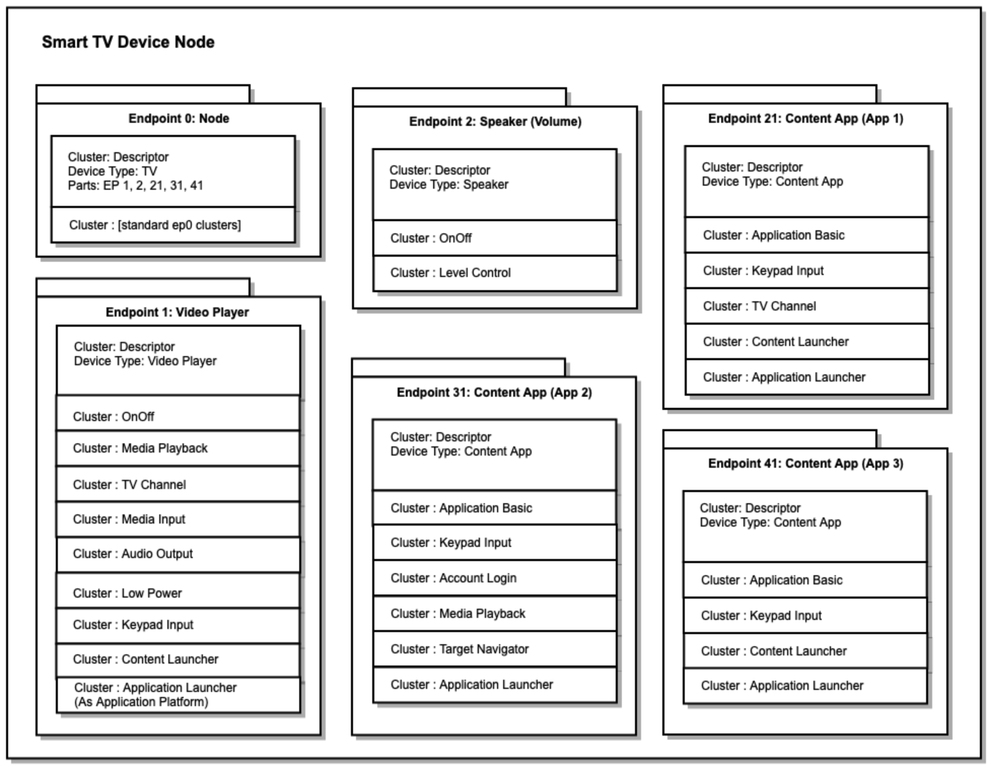
6.2. Account Login Cluster
This cluster provides commands that facilitate user account login on a Content App or a node. For example, a Content App running on a Video Player device, which is represented as an endpoint (see Device Type Library document), can use this cluster to help make the user account on the Content App match the user account on the Client.
6.2.1. Overview
The cluster server for this cluster may be supported on each endpoint that represents a Content App on a Video Player device.
See Device Type Library document for details of how a Content App, represented as an endpoint on the Video Player device, may implement the cluster server for this cluster to simplify account login for its users.
6.2.2. Features
This cluster SHALL support the FeatureMap bitmap attribute as defined below.
| Bit | Code | Feature | Description |
|---|
6.2.4. Commands
| ID | Name | Direction | Response | Access | Conformance |
|---|---|---|---|---|---|
|
0x00 |
GetSetupPIN |
Client ⇒ Server |
GetSetupPINResponse |
T A |
M |
|
0x01 |
GetSetupPINResponse |
Server ⇒ Client |
N |
M |
|
|
0x02 |
Login |
Client ⇒ Server |
Y |
T A |
M |
|
0x03 |
Logout |
Client ⇒ Server |
Y |
T O |
M |
6.2.4.1. GetSetupPIN Command
The purpose of this command is to determine if the active user account of the given Content App matches the active user account of a given Commissionee, and when it does, return a Setup PIN code which can be used for password-authenticated session establishment (PASE) with the Commissionee.
For example, a Video Player with a Content App Platform may invoke this command on one of its Content App endpoints to facilitate commissioning of a Phone App made by the same vendor as the Content App. If the accounts match, then the Content App may return a setup code that can be used by the Video Player to commission the Phone App without requiring the user to physically input a setup code.
The account match is determined by the Content App using a method which is outside the scope of this specification and will typically involve a central service which is in communication with both the Content App and the Commissionee. The GetSetupPIN command is needed in order to provide the Commissioner/Admin with a Setup PIN when this Commissioner/Admin is operated by a different vendor from the Content App.
This method is used to facilitate Setup PIN exchange (for PASE) between Commissioner and Commissionee when the same user account is active on both nodes. With this method, the Content App satisfies proof of possession related to commissioning by requiring the same user account to be active on both Commissionee and Content App, while the Commissioner/Admin ensures user consent by prompting the user prior to invocation of the command.
Upon receipt of this command, the Content App checks if the account associated with the Temporary Account Identifier sent by the client is the same account that is active on itself. If the accounts are the same, then the Content App returns the GetSetupPIN Response which includes a Setup PIN that may be used for PASE with the Commissionee.
The Temporary Account Identifier for a Commissionee may be populated with the Rotating ID field of the client’s commissionable node advertisement (see Rotating Device Identifier section in [MatterCore] ) encoded as an octet string where the octets of the Rotating Device Identifier are encoded as 2-character sequences by representing each octet’s value as a 2-digit hexadecimal number, using uppercase letters.
The Setup PIN is an 11 character string so that it can accommodate different future formats, including alpha-numeric encodings. For a Commissionee it SHALL be populated with the Manual Pairing Code (see Manual Pairing Code section in [MatterCore] ) encoded as a string.
The Server SHALL implement rate limiting to prevent brute force attacks. No more than 10 unique requests in a 10 minute period SHALL be allowed; a command response status of FAILURE should sent for additional commands received within the 10 minute period. Because access to this command is limited to nodes with Admin-level access, and the user is prompted for consent prior to Commissioning, there are in place multiple obstacles to successfully mounting a brute force attack. A Content App that supports this command SHALL ensure that the Temporary Account Identifier used by its clients is not valid for more than 10 minutes.
| ID | Field | Type | Constraint | Quality | Default | Conformance |
|---|---|---|---|---|---|---|
|
0 |
TempAccountIdentifier |
string |
min 16 max 100 |
M |
6.2.4.2. GetSetupPINResponse Command
This message is sent in response to the GetSetupPIN command, and contains the Setup PIN code, or null when the account identified in the request does not match the active account of the running Content App.
| ID | Field | Type | Constraint | Quality | Default | Conformance |
|---|---|---|---|---|---|---|
|
0 |
SetupPIN |
string |
min 11 |
X |
M |
6.2.4.3. Login Command
The purpose of this command is to allow the Content App to assume the user account of a given Commissionee by leveraging the Setup PIN code input by the user during the commissioning process.
For example, a Video Player with a Content App Platform may invoke this command on one of its Content App endpoints after the commissioning has completed of a Phone App made by the same vendor as the Content App. The Content App may determine whether the Temporary Account Identifier maps to an account with a corresponding Setup PIN and, if so, it may automatically login to the account for the corresponding user. The end result is that a user performs commissioning of a Phone App to a Video Player by inputting the Setup PIN for the Phone App into the Video Player UX. Once commissioning has completed, the Video Player invokes this command to allow the corresponding Content App to assume the same user account as the Phone App.
The verification of Setup PIN for the given Temporary Account Identifier is determined by the Content App using a method which is outside the scope of this specification and will typically involve a central service which is in communication with both the Content App and the Commissionee. Implementations of such a service should impose aggressive time outs for any mapping of Temporary Account Identifier to Setup PIN in order to prevent accidental login due to delayed invocation.
Upon receipt, the Content App checks if the account associated with the client’s Temp Account Identifier has a current active Setup PIN with the given value. If the Setup PIN is valid for the user account associated with the Temp Account Identifier, then the Content App MAY make that user account active.
The Temporary Account Identifier for a Commissionee may be populated with the Rotating ID field of the client’s commissionable node advertisement encoded as an octet string where the octets of the Rotating Device Identifier are encoded as 2-character sequences by representing each octet’s value as a 2-digit hexadecimal number, using uppercase letters.
The Setup PIN for a Commissionee may be populated with the Manual Pairing Code encoded as a string of decimal numbers.
The Server SHALL implement rate limiting to prevent brute force attacks. No more than 10 unique requests in a 10 minute period SHALL be allowed; a command response status of FAILURE should sent for additional commands received within the 10 minute period. Because access to this command is limited to nodes with Admin-level access, and the user is involved when obtaining the SetupPIN, there are in place multiple obstacles to successfully mounting a brute force attack. A Content App that supports this command SHALL ensure that the Temporary Account Identifier used by its clients is not valid for more than 10 minutes.
| ID | Field | Type | Constraint | Quality | Default | Conformance |
|---|---|---|---|---|---|---|
|
0 |
TempAccountIdentifier |
string |
min 16 max 100 |
M |
||
|
1 |
SetupPIN |
string |
min 11 |
M |
6.3. Application Basic Cluster
This cluster provides information about a Content App running on a Video Player device which is represented as an endpoint (see Device Type Library document).
6.3.1. Overview
The cluster server for this cluster should be supported on each endpoint that represents a Content App on a Video Player device. This cluster provides identification information about the Content App such as vendor and product.
6.3.2. Features
This cluster SHALL support the FeatureMap bitmap attribute as defined below.
| Bit | Code | Feature | Description |
|---|
6.3.3. Attributes
| ID | Name | Type | Constraint | Quality | Default | Access | Conformance |
|---|---|---|---|---|---|---|---|
|
0x0000 |
VendorName |
string |
max 32 |
F |
empty |
R V |
O |
|
0x0001 |
VendorID |
vendor-id |
all |
F |
R V |
O |
|
|
0x0002 |
ApplicationName |
string |
desc |
F |
R V |
M |
|
|
0x0003 |
ProductID |
uint16 |
all |
F |
R V |
O |
|
|
0x0004 |
Application |
|
desc |
F |
R V |
M |
|
|
0x0005 |
Status |
ApplicationStatusEnum |
desc |
ms |
R V |
M |
|
|
0x0006 |
ApplicationVersion |
string |
max 32 |
F |
R V |
M |
|
|
0x0007 |
AllowedVendorList |
list[vendor-id] |
none |
F |
R A |
M |
6.3.3.1. VendorName Attribute
This attribute SHALL specify a human readable (displayable) name of the vendor for the Content App.
6.3.3.2. VendorID Attribute
This attribute, if present, SHALL specify the Connectivity Standards Alliance assigned Vendor ID for the Content App.
6.3.3.3. ApplicationName Attribute
This attribute SHALL specify a human readable (displayable) name of the Content App assigned by the vendor. For example, "NPR On Demand". The maximum length of the ApplicationName attribute is 256 bytes of UTF-8 characters.
6.3.3.4. ProductID Attribute
This attribute, if present, SHALL specify a numeric ID assigned by the vendor to identify a specific Content App made by them. If the Content App is certified by the Connectivity Standards Alliance, then this would be the Product ID as specified by the vendor for the certification.
6.3.3.5. Application Attribute
This attribute SHALL specify a Content App which consists of an Application ID using a specified catalog.
6.3.3.6. Status Attribute
This attribute SHALL specify the current running status of the application.
6.3.4. Data Types
6.3.4.1.
Application
ApplicationStruct
This indicates a global identifier for an Application given a catalog.
| ID | Name | Type | Constraint | Quality | Default | Conformance |
|---|---|---|---|---|---|---|
|
0 |
CatalogVendorID |
uint16 |
all |
M |
||
|
1 |
ApplicationID |
string |
all |
M |
6.3.4.1.1. CatalogVendorID
This SHALL indicate the Connectivity Standards Alliance issued vendor ID for the catalog. The DIAL registry SHALL use value 0x0000.
It is assumed that Content App Platform providers (see Video Player Architecture section in [MatterDevLib] ) will have their own catalog vendor ID (set to their own Vendor ID) and will assign an ApplicationID to each Content App.
6.3.4.2. ApplicationStatusEnum
ApplicationStatusEnum Data Type is derived from enum8.
| Value | Name | Conformance | Description |
|---|---|---|---|
|
0 |
|
M |
Application is not running. |
|
1 |
|
M |
Application is running, is visible to the user, and is the active target for input. |
|
2 |
|
M |
Application is running but not visible to the user. |
|
3 |
|
M |
Application is running and visible, but is not the active target for input. |
6.4. Application Launcher Cluster
This cluster provides an interface for launching applications on a Video Player device such as a TV.
6.4.1. Overview
This cluster is supported on endpoints that can launch Applications, such as a Casting Video Player device with a Content App Platform. It supports identifying an Application by global identifier from a given catalog, and launching it. It also supports tracking the currently in-focus Application.
Depending
on
the
support
for
the
Application
Platform
feature,
the
cluster
can
either
support
launching
the
application
corresponding
to
the
endpoint
on
which
the
cluster
is
supported
(
AP
feature
not
supported)
or
it
can
support
launching
any
application
(
AP
feature
supported).
6.4.2. Features
This cluster SHALL support the FeatureMap bitmap attribute as defined below.
| Bit | Code | Feature | Description |
|---|---|---|---|
|
0 |
AP |
Application Platform |
Support for attributes and commands required for endpoint to support launching any application within the supported application catalogs |
6.4.3. Attributes
| ID | Name | Type | Constraint | Quality | Default | Access | Conformance |
|---|---|---|---|---|---|---|---|
|
0x0000 |
CatalogList |
list[uint16] |
none |
N |
R V |
AP |
|
|
0x0001 |
CurrentApp |
|
desc |
X |
null |
R V |
O |
6.4.3.1. CatalogList Attribute
This attribute SHALL specify the list of supported application catalogs, where each entry in the list is the CSA-issued vendor ID for the catalog. The DIAL registry (see [ DIAL Registry ]) SHALL use value 0x0000.
It is expected that Content App Platform providers will have their own catalog vendor ID (set to their own Vendor ID) and will assign an ApplicationID to each Content App.
6.4.3.2. CurrentApp Attribute
This attribute SHALL specify the current in-focus application, identified using an Application ID, catalog vendor ID and the corresponding endpoint number when the application is represented by a Content App endpoint. A null SHALL be used to indicate there is no current in-focus application.
6.4.4. Commands
| ID | Name | Direction | Response | Access | Conformance |
|---|---|---|---|---|---|
|
0x00 |
LaunchApp |
Client ⇒ Server |
LauncherResponse |
O |
M |
|
0x01 |
StopApp |
Client ⇒ Server |
LauncherResponse |
O |
M |
|
0x02 |
HideApp |
Client ⇒ Server |
LauncherResponse |
O |
M |
|
0x03 |
LauncherResponse |
Server ⇒ Client |
N |
M |
6.4.4.1. LaunchApp Command
Upon receipt of this command, the server SHALL launch the application with optional data. The application SHALL be either
-
the specified application, if the Application Platform feature is supported;
-
otherwise the application corresponding to the endpoint.
The
endpoint
SHALL
launch
and
bring
to
foreground
the
requisite
application
if
the
application
is
not
already
launched
and
in
foreground.
The
Status
attribute
SHALL
be
updated
to
ACTIVE_VISIBLE_FOCUS
on
the
Application
Basic
cluster
of
the
Endpoint
corresponding
to
the
launched
application.
The
Status
attribute
SHALL
be
updated
on
any
other
application
whose
Status
MAY
have
changed
as
a
result
of
this
command.
The
CurrentApp
attribute,
if
supported,
SHALL
be
updated
to
reflect
the
new
application
in
the
foreground.
This command returns a Launcher Response.
| ID | Field | Type | Constraint | Quality | Default | Conformance |
|---|---|---|---|---|---|---|
|
0 |
Application |
|
desc |
AP |
||
|
1 |
Data |
octstr |
any |
ms |
O |
6.4.4.1.2. Data
This field SHALL specify optional app-specific data to be sent to the app.
Note: This format and meaning of this value is proprietary and outside the specification. It provides a transition path for device makers that use other protocols (like DIAL) which allow for proprietary data. Apps that are not yet Matter aware can be launched via Matter, while retaining the existing ability to launch with proprietary data.
6.4.4.2. StopApp Command
Upon receipt of this command, the server SHALL stop the application if it is running. The application SHALL be either
-
the specified application, if the Application Platform feature is supported;
-
otherwise the application corresponding to the endpoint.
The
Status
attribute
SHALL
be
updated
to
STOPPED
on
the
Application
Basic
cluster
of
the
Endpoint
corresponding
to
the
stopped
application.
The
Status
attribute
SHALL
be
updated
on
any
other
application
whose
Status
MAY
have
changed
as
a
result
of
this
command.
This command returns a Launcher Response.
| ID | Field | Type | Constraint | Quality | Default | Conformance |
|---|---|---|---|---|---|---|
|
0 |
Application |
|
desc |
ms |
AP |
6.4.4.3. HideApp Command
Upon receipt of this command, the server SHALL hide the application. The application SHALL be either
-
the specified application, if the Application Platform feature is supported;
-
otherwise the application corresponding to the endpoint.
The
endpoint
MAY
decide
to
stop
the
application
based
on
manufacturer
specific
behavior
or
resource
constraints
if
any.
The
Status
attribute
SHALL
be
updated
to
ACTIVE_HIDDEN
or
STOPPED
,
depending
on
the
action
taken,
on
the
Application
Basic
cluster
of
the
Endpoint
corresponding
to
the
application
on
which
the
action
was
taken.
The
Status
attribute
SHALL
be
updated
on
any
other
application
whose
Status
MAY
have
changed
as
a
result
of
this
command.
This command returns a Launcher Response.
| ID | Field | Type | Constraint | Quality | Default | Conformance |
|---|---|---|---|---|---|---|
|
0 |
Application |
|
desc |
ms |
AP |
6.4.5. Data Types
6.4.5.1. StatusEnum
StatusEnum Data Type is derived from enum8.
| Value | Name | Conformance | Description |
|---|---|---|---|
|
0 |
|
M |
Command succeeded |
|
1 |
|
M |
Requested app is not available. |
|
2 |
|
M |
Video platform unable to honor command. |
6.4.5.2.
Application
ApplicationStruct
This indicates a global identifier for an Application given a catalog.
| ID | Name | Type | Constraint | Quality | Default | Conformance |
|---|---|---|---|---|---|---|
|
0 |
CatalogVendorID |
uint16 |
all |
M |
||
|
1 |
ApplicationID |
string |
all |
M |
6.4.5.2.1. CatalogVendorID
This SHALL indicate the CSA-issued vendor ID for the catalog. The DIAL registry SHALL use value 0x0000.
Content App Platform providers will have their own catalog vendor ID (set to their own Vendor ID) and will assign an ApplicationID to each Content App.
6.4.5.2.2. ApplicationID
This SHALL indicate the application identifier, expressed as a string, such as "PruneVideo" or "Company X". This field SHALL be unique within a catalog.
For the DIAL registry catalog, this value SHALL be the DIAL prefix (see [ DIAL Registry ]).
6.5. Audio Output Cluster
This cluster provides an interface for controlling the Output on a Video Player device such as a TV.
6.5.1. Overview
This cluster would be supported on a device with audio outputs like a Video Player device (Smart TV, TV Setup Top Box, Smart Speaker, etc).
This cluster provides the list of available outputs and provides commands for selecting and renaming them.
The cluster server for Audio Output is implemented by a device that has configurable audio output.
6.5.2. Features
This cluster SHALL support the FeatureMap bitmap attribute as defined below.
| Bit | Code | Feature | Description |
|---|---|---|---|
|
0 |
NU |
Name Updates |
Supports updates to output names |
6.5.3. Attributes
| ID | Name | Type | Constraint | Quality | Default | Access | Conformance |
|---|---|---|---|---|---|---|---|
|
0x0000 |
OutputList |
|
none |
R V |
M |
||
|
0x0001 |
CurrentOutput |
uint8 |
all |
R V |
M |
6.5.4. Commands
| ID | Name | Direction | Response | Access | Conformance |
|---|---|---|---|---|---|
|
0x00 |
SelectOutput |
Client ⇒ Server |
Y |
O |
M |
|
0x01 |
RenameOutput |
Client ⇒ Server |
Y |
M |
NU |
6.5.4.1. SelectAudioOutput Command
Upon receipt, this SHALL change the output on the device to the output at a specific index in the Output List.
Note that when the current output is set to an output of type HDMI, adjustments to volume via a Speaker endpoint on the same node MAY cause HDMI volume up/down commands to be sent to the given HDMI output.
| ID | Field | Type | Constraint | Quality | Default | Conformance |
|---|---|---|---|---|---|---|
|
0 |
Index |
uint8 |
all |
M |
6.5.4.2. RenameOutput Command
Upon receipt, this SHALL rename the output at a specific index in the Output List.
Updates to the output name SHALL appear in the device’s settings menus. Name updates MAY automatically be sent to the actual device to which the output connects.
| ID | Field | Type | Constraint | Quality | Default | Conformance |
|---|---|---|---|---|---|---|
|
0 |
Index |
uint8 |
all |
M |
||
|
1 |
Name |
string |
all |
M |
6.6. Channel Cluster
This cluster provides an interface for controlling the current Channel on a device or endpoint.
6.6.1. Overview
This cluster server would be supported on Video Player devices or endpoints that allow Channel control such as a Content App. This cluster provides a list of available channels and provides commands for absolute and relative channel changes.
The cluster server for Channel is implemented by an endpoint that controls the current Channel.
6.6.2. Features
This cluster SHALL support the FeatureMap bitmap attribute as defined below.
| Bit | Code | Feature | Description |
|---|---|---|---|
|
0 |
CL |
Channel List |
Provides list of available channels. |
|
1 |
LI |
Lineup Info |
Provides lineup info, which is a reference to an external source of lineup information. |
6.6.3. Attributes
| ID | Name | Type | Constraint | Quality | Default | Access | Conformance |
|---|---|---|---|---|---|---|---|
|
0x0000 |
ChannelList |
|
none |
empty |
R V |
CL |
|
|
0x0001 |
Lineup |
|
desc |
R V |
LI |
||
|
0x0002 |
CurrentChannel |
|
desc |
X |
null |
R V |
O |
6.6.4. Commands
| ID | Name | Direction | Response | Access | Conformance |
|---|---|---|---|---|---|
|
0x00 |
ChangeChannel |
Client ⇒ Server |
ChangeChannelResponse |
O |
CL or LI |
|
0x01 |
ChangeChannelResponse |
Server ⇒ Client |
N |
CL or LI |
|
|
0x02 |
ChangeChannelByNumber |
Client ⇒ Server |
Y |
O |
M |
|
0x03 |
SkipChannel |
Client ⇒ Server |
Y |
O |
M |
6.6.4.1. ChangeChannel Command
Change the channel to the channel case-insensitive exact matching the value passed as an argument.
The match priority order SHALL be: AffiliateCallSign ("KCTS"), CallSign ("PBS"), Name ("Comedy Central"), Number ("13.1")
Upon receipt, this SHALL generate a ChangeChannelResponse command.
Upon success, the CurrentChannel attribute, if supported, SHALL be updated to reflect the change.
The data for this command SHALL be as follows:
| ID | Field | Type | Constraint | Quality | Default | Conformance |
|---|---|---|---|---|---|---|
|
0 |
Match |
string |
M |
6.6.4.2. ChangeChannelResponse Command
This command SHALL be generated in response to a ChangeChannel command. The data for this command SHALL be as follows:
| ID | Field | Type | Constraint | Quality | Default | Conformance |
|---|---|---|---|---|---|---|
|
0 |
Status |
StatusEnum |
desc |
M |
||
|
1 |
Data |
octstr |
any |
O |
6.6.4.3. ChangeChannelByNumber Command
Change the channel to the channel with the given Number in the ChannelList attribute.
The data for this command SHALL be as follows:
| ID | Field | Type | Constraint | Quality | Default | Conformance |
|---|---|---|---|---|---|---|
|
0 |
|
uint16 |
all |
M |
||
|
1 |
|
uint16 |
all |
M |
6.6.4.4. SkipChannel Command
This command provides channel up and channel down functionality, but allows channel index jumps of size Count .
When the value of the increase or decrease is larger than the number of channels remaining in the given direction, then the behavior SHALL be to return to the beginning (or end) of the channel list and continue. For example, if the current channel is at index 0 and count value of -1 is given, then the current channel should change to the last channel.
The data for this command is as follows:
| ID | Field | Type | Constraint | Quality | Default | Conformance |
|---|---|---|---|---|---|---|
|
0 |
Count |
int16 |
all |
M |
6.6.5. Data Types
6.6.5.1.
ChannelInfo
ChannelInfoStruct
This indicates a channel in a channel lineup.
While
the
major
and
minor
numbers
in
the
ChannelInfo
ChannelInfoStruct
support
use
of
ATSC
channel
format,
a
lineup
MAY
use
other
formats
which
can
map
into
these
numeric
values.
| ID | Name | Type | Constraint | Quality | Default | Conformance |
|---|---|---|---|---|---|---|
|
0 |
|
uint16 |
all |
M |
||
|
1 |
|
uint16 |
all |
M |
||
|
2 |
Name |
string |
empty |
O |
||
|
3 |
CallSign |
string |
empty |
O |
||
|
4 |
AffiliateCallSign |
string |
empty |
O |
6.6.5.1.1.
majorNumber
MajorNumber
This SHALL indicate the channel major number value (for example, using ATSC format). When the channel number is expressed as a string, such as "13.1" or "256", the major number would be 13 or 256, respectively.
6.6.5.1.2.
minorNumber
MinorNumber
This SHALL indicate the channel minor number value (for example, using ATSC format). When the channel number is expressed as a string, such as "13.1" or "256", the minor number would be 1 or 0, respectively.
6.6.5.1.3. Name
This SHALL indicate the marketing name for the channel, such as “The CW" or "Comedy Central". This field is optional, but SHOULD be provided when known.
6.6.5.2.
LineupInfo
LineupInfoStruct
The Lineup Info allows references to external lineup sources like Gracenote. The combination of OperatorName, LineupName, and PostalCode MUST uniquely identify a lineup.
| ID | Name | Type | Constraint | Quality | Default | Conformance |
|---|---|---|---|---|---|---|
|
0 |
OperatorName |
string |
M |
|||
|
1 |
LineupName |
string |
empty |
O |
||
|
2 |
PostalCode |
string |
empty |
O |
||
|
3 |
LineupInfoType |
desc |
M |
6.6.5.2.2. Lineup Name
This SHALL indicate the name of the provider lineup, for example "Comcast King County". This field is optional, but SHOULD be provided when known.
6.6.5.3. LineupInfoTypeEnum
LineupInfoTypeEnum Data Type is derived from enum8.
| Value | Name | Conformance | Description |
|---|---|---|---|
|
0 |
MSO |
M |
MultiSystemOperator |
6.6.5.4. StatusEnum
StatusEnum Data Type is derived from enum8.
| Value | Name | Conformance | Description |
|---|---|---|---|
|
0 |
|
M |
Command succeeded |
|
1 |
|
M |
More
than
one
equal
match
for
the
|
|
2 |
|
M |
No
matches
for
the
|
6.7. Content Launcher Cluster
This cluster provides an interface for launching content on a Video Player device such as a Streaming Media Player, Smart TV or Smart Screen.
6.7.1. Overview
This cluster would be supported on a Video Player device or devices that can playback content, such as a Streaming Media Player, Smart TV or Smart Screen. This cluster supports playing back content referenced by URL. It supports finding content by type and global identifier, and either playing the content or displaying the search results.
The cluster server for Content Launcher is implemented by an endpoint that can launch content, such as a Video Player, or an endpoint representing a Content App on such a device.
When this cluster is implemented for an Content App Endpoint (Endpoint with type “Content App” and having an Application Basic cluster), the Video Player device SHALL launch the application when a client invokes the LaunchContent or LaunchURL commands.
6.7.2. Features
This cluster SHALL support the FeatureMap bitmap attribute as defined below.
| Bit | Code | Feature | Description |
|---|---|---|---|
|
0 |
CS |
Content Search |
Device supports content search (non-app specific) |
|
1 |
UP |
URL Playback |
Device supports basic URL-based file playback |
6.7.3. Attributes
| ID | Name | Type | Constraint | Quality | Default | Access | Conformance |
|---|---|---|---|---|---|---|---|
|
0x0000 |
AcceptHeader |
list[string] |
max 100[max 1024] |
N |
empty |
R V |
UP |
|
0x0001 |
SupportedStreamingProtocols |
map32 |
N |
0 |
R V |
UP |
6.7.3.1. AcceptHeader Attribute
This list provides list of content types supported by the Video Player or Content App in the form of entries in the HTTP "Accept" request header.
6.7.4. Commands
| ID | Name | Direction | Response | Access | Conformance |
|---|---|---|---|---|---|
|
0x00 |
LaunchContent |
Client ⇒ Server |
LauncherResponse |
O |
CS |
|
0x01 |
LaunchURL |
Client ⇒ Server |
LauncherResponse |
O |
UP |
|
0x02 |
LauncherResponse |
Server ⇒ Client |
N |
CS | UP |
6.7.4.1. LaunchContent Command
Upon receipt, this SHALL launch the specified content with optional search criteria.
This command returns a Launch Response.
| ID | Field | Type | Constraint | Quality | Default | Conformance |
|---|---|---|---|---|---|---|
|
0 |
Search |
|
desc |
M |
||
|
1 |
AutoPlay |
bool |
desc |
M |
||
|
2 |
Data |
octstr |
ms |
O |
6.7.4.2. LaunchURL Command
Upon receipt, this SHALL launch content from the specified URL.
The content types supported include those identified in the AcceptHeader and SupportedStreamingProtocols attributes.
A check SHALL be made to ensure the URL is secure (uses HTTPS).
This command returns a Launch Response.
| ID | Field | Type | Constraint | Quality | Default | Conformance |
|---|---|---|---|---|---|---|
|
0 |
ContentURL |
string |
any |
M |
||
|
1 |
DisplayString |
string |
any |
ms |
O |
|
|
2 |
BrandingInformation |
|
any |
ms |
O |
6.7.5. Data Types
6.7.5.1. StatusEnum
StatusEnum Data Type is derived from enum8.
| Value | Name | Conformance | Description |
|---|---|---|---|
|
0 |
|
M |
Command succeeded |
|
1 |
|
M |
Requested URL could not be reached by device. |
|
2 |
|
M |
Requested URL returned 401 error code. |
6.7.5.2.
ContentSearch
ContentSearchStruct
This object defines inputs to a search for content for display or playback.
| ID | Name | Type | Constraint | Quality | Default | Conformance |
|---|---|---|---|---|---|---|
|
0 |
ParameterList |
|
all |
0 |
M |
6.7.5.2.1. ParameterList
This SHALL indicate the list of parameters comprising the search. If multiple parameters are provided, the search parameters SHALL be joined with 'AND' logic. e.g. action movies with Tom Cruise will be represented as [{Actor: 'Tom Cruise'}, {Type: 'Movie'}, {Genre: 'Action'}]
6.7.5.3.
Parameter
ParameterStruct
This object defines inputs to a search for content for display or playback.
| ID | Name | Type | Constraint | Quality | Default | Conformance |
|---|---|---|---|---|---|---|
|
0 |
Type |
ParameterEnum |
all |
M |
||
|
1 |
Value |
string |
max 1024 |
M |
||
|
2 |
ExternalIDList |
|
all |
empty |
O |
6.7.5.4. ParameterEnum
Parameter Data Type is derived from enum8.
| Value | Name | Conformance | Description |
|---|---|---|---|
|
0 |
Actor |
M |
Actor represents an actor credited in video media content; for example, “Gaby sHoffman” |
|
1 |
Channel |
M |
Channel represents the identifying data for a television channel; for example, "PBS" |
|
2 |
Character |
M |
A character represented in video media content; for example, “Snow White” |
|
3 |
Director |
M |
A director of the video media content; for example, “Spike Lee” |
|
4 |
Event |
M |
An event is a reference to a type of event; examples would include sports, music, or other types of events. For example, searching for "Football games" would search for a 'game' event entity and a 'football' sport entity. |
|
5 |
Franchise |
M |
A franchise is a video entity which can represent a number of video entities, like movies or TV shows. For example, take the fictional franchise "Intergalactic Wars" which represents a collection of movie trilogies, as well as animated and live action TV shows. This entity type was introduced to account for requests by customers such as "Find Intergalactic Wars movies", which would search for all 'Intergalactic Wars' programs of the MOVIE MediaType, rather than attempting to match to a single title. |
|
6 |
Genre |
M |
Genre represents the genre of video media content such as action, drama or comedy. |
|
7 |
League |
M |
League represents the categorical information for a sporting league; for example, "NCAA" |
|
8 |
Popularity |
M |
Popularity indicates whether the user asks for popular content. |
|
9 |
Provider |
M |
The provider (MSP) the user wants this media to be played on; for example, "Netflix". |
|
10 |
Sport |
M |
Sport represents the categorical information of a sport; for example, football |
|
11 |
SportsTeam |
M |
SportsTeam represents the categorical information of a professional sports team; for example, "University of Washington Huskies" |
|
12 |
Type |
M |
The type of content requested. Supported types are "Movie", "MovieSeries", "TVSeries", "TVSeason", "TVEpisode", "SportsEvent", and "Video" |
|
13 |
Video |
M |
Video represents the identifying data for a specific piece of video content; for example, "Manchester by the Sea". |
6.7.5.5.
AdditionalInfo
AdditionalInfoStruct
This object defines additional name=value pairs that can be used for identifying content.
| ID | Name | Type | Constraint | Quality | Default | Conformance |
|---|---|---|---|---|---|---|
|
0 |
Name |
string |
max 256 |
M |
||
|
1 |
Value |
string |
max 8192 |
M |
6.7.5.6.
BrandingInformation
BrandingInformationStruct
This object defines Branding Information which can be provided by the client in order to customize the skin of the Video Player during playback.
| ID | Field | Type | Constraint | Quality | Default | Conformance |
|---|---|---|---|---|---|---|
|
0 |
ProviderName |
string |
max 256 |
M |
||
|
1 |
Background |
|
ms |
O |
||
|
2 |
Logo |
|
ms |
O |
||
|
3 |
ProgressBar |
|
ms |
O |
||
|
4 |
Splash |
|
ms |
O |
||
|
5 |
WaterMark |
|
ms |
O |
6.7.5.6.2. Background
This SHALL indicate background of the Video Player while content launch request is being processed by it. This background information MAY also be used by the Video Player when it is in idle state.
6.7.5.6.3. Logo
This
SHALL
indicate
the
logo
shown
when
the
Video
Player
is
launching.
This
is
also
used
when
the
Video
Player
is
in
the
idle
state
and
Splash
field
is
not
available.
6.7.5.7.
StyleInformation
StyleInformationStruct
This
object
defines
StyleInformation
style
information
which
can
be
used
by
content
providers
to
change
the
Media
Player’s
style
related
properties.
| ID | Field | Type | Constraint | Quality | Default | Conformance |
|---|---|---|---|---|---|---|
|
0 |
|
string |
max 8192 |
ms |
O |
|
|
1 |
Color |
string |
7,9 |
ms |
O |
|
|
2 |
Size |
|
ms |
O |
6.7.5.7.1.
ImageUrl
ImageURL
This SHALL indicate the URL of image used for Styling different Video Player sections like Logo, Watermark etc.
6.7.5.7.2. Color
This SHALL indicate the color, in RGB or RGBA, used for styling different Video Player sections like Logo, Watermark, etc. The value SHALL conform to the 6-digit or 8-digit format defined for CSS sRGB hexadecimal color notation . Examples:
-
#76DE19forR=0x76,G=0xDE,B=0x19,Aabsent -
#76DE1980forR=0x76,G=0xDE,B=0x19,A=0x80
6.7.5.8.
Dimension
DimensionStruct
This object defines dimension which can be used for defining Size of background images.
TODO : Evaluate if Dimension should be part of common data types. As of Apr 2021 adding it in ContentLauncher because we don’t have any other usecases which require this datatype.
| ID | Field | Type | Constraint | Quality | Default | Conformance |
|---|---|---|---|---|---|---|
|
0 |
Width |
double |
ms |
M |
||
|
1 |
Height |
double |
ms |
M |
||
|
2 |
Metric |
MetricTypeEnum |
M |
6.7.5.9. MetricTypeEnum
MetricTypeEnum Data Type is derived from enum8.
| Value | Name | Conformance |
|---|---|---|
|
0 |
Pixels |
M |
|
1 |
Percentage |
M |
6.7.5.9.2. Percentage
This value is for dimensions defined as a percentage of the overall display dimensions. For example, if using a Percentage Metric type for a Width measurement of 50.0, against a display width of 1920 pixels, then the resulting value used would be 960 pixels (50.0% of 1920) for that dimension. Whenever a measurement uses this Metric type, the resulting values SHALL be rounded ("floored") towards 0 if the measurement requires an integer final value.
6.8. Keypad Input Cluster
This cluster provides an interface for key code based input and control on a device like a Video Player or an endpoint like a Content App. This may include text or action commands such as UP, DOWN, and SELECT.
6.8.1. Overview
This cluster would be supported on Video Player devices as well as devices that support remote control input from a keypad or remote. This cluster provides the list of supported keypad inputs and provides a command for sending them.
The cluster server for Keypad Input is implemented by a device that can receive keypad input, such as a Video Player, or an endpoint that can receive keypad input, such as a Content App.
The key codes used are those defined in the HDMI CEC specification (see HDMI ).
Devices MAY understand a subset of these key codes. Feature flags are used to indicate a specific subset that is supported. Device MAY support additional codes beyond what is indicated in feature flags.
6.8.2. Features
This cluster SHALL support the FeatureMap bitmap attribute as defined below.
| Bit | Code | Feature | Description |
|---|---|---|---|
|
0 |
NV |
Navigation KeyCodes |
Supports UP, DOWN, LEFT, RIGHT, SELECT, BACK, EXIT, MENU |
|
1 |
LK |
Location Keys |
Supports CEC keys 0x0A (Settings) and 0x09 (Home) |
|
2 |
NK |
Number Keys |
Supports numeric input 0..9 |
6.8.3. Commands
| Id | Name | Direction | Response | Access | Conformance |
|---|---|---|---|---|---|
|
0x00 |
SendKey |
Client ⇒ Server |
SendKeyResponse |
O |
M |
|
0x01 |
SendKeyResponse |
Server ⇒ Client |
N |
M |
6.8.3.1. SendKey Command
Upon receipt, this SHALL process a keycode as input to the media device.
If a second SendKey request with the same KeyCode value is received within 200ms, then the endpoint will consider the first key press to be a press and hold. When such a repeat KeyCode value is not received within 200ms, then the endpoint will consider the last key press to be a release.
| Id | Field | Type | Constraint | Quality | Default | Conformance |
|---|---|---|---|---|---|---|
|
0 |
KeyCode |
uint8 |
all |
M |
6.8.4. Data Types
6.8.4.1. StatusEnum
Status Data Type is derived from enum8.
| Value | Name | Conformance | Description |
|---|---|---|---|
|
0 |
|
M |
Command succeeded |
|
1 |
|
M |
Command failed: Key code is not supported. |
|
2 |
|
M |
Command failed: Requested key code is invalid in the context of the responder’s current state. |
6.9. Media Input Cluster
This cluster provides an interface for controlling the Input Selector on a media device such as a Video Player.
6.9.1. Overview
This cluster would be implemented on TV and other media streaming devices, as well as devices that provide input to or output from such devices.
This cluster provides the list of available inputs and provides commands for selecting and renaming them.
The cluster server for Media Input is implemented by a device that has selectable input, such as a Video Player device.
6.9.2. Features
This cluster SHALL support the FeatureMap bitmap attribute as defined below.
| Bit | Code | Feature | Description |
|---|---|---|---|
|
0 |
NU |
Name Updates |
Supports updates to the input names |
6.9.3. Attributes
| Id | Name | Type | Constraint | Quality | Default | Access | Conformance |
|---|---|---|---|---|---|---|---|
|
0x0000 |
InputList |
|
R V |
M |
|||
|
0x0001 |
CurrentInput |
uint8 |
all |
R V |
M |
6.9.4. Commands
| Id | Name | Direction | Response | Access | Conformance |
|---|---|---|---|---|---|
|
0x00 |
SelectInput |
Client ⇒ Server |
Y |
O |
M |
|
0x01 |
ShowInputStatus |
Client ⇒ Server |
Y |
O |
M |
|
0x02 |
HideInputStatus |
Client ⇒ Server |
Y |
O |
M |
|
0x03 |
RenameInput |
Client ⇒ Server |
Y |
M |
NU |
6.9.4.1. SelectInput Command
Upon receipt, this SHALL change the media input on the device to the input at a specific index in the Input List.
| Id | Field | Type | Constraint | Quality | Default | Conformance |
|---|---|---|---|---|---|---|
|
0 |
Index |
uint8 |
all |
M |
6.9.5. Data Types
6.9.5.1.
InputInfo
InputInfoStruct
This contains information about an input.
| Id | Name | Type | Constraint | Quality | Default | Conformance |
|---|---|---|---|---|---|---|
|
0 |
Index |
uint8 |
all |
M |
||
|
1 |
InputType |
InputTypeEnum |
desc |
M |
||
|
2 |
Name |
string |
M |
|||
|
3 |
Description |
string |
M |
6.9.5.2. InputTypeEnum
InputType Data Type is derived from enum8.
The type of input, expressed as an enum, with the following values:
| Value | Name | Conformance | Description |
|---|---|---|---|
|
0 |
|
M |
Indicates content not coming from a physical input. |
|
1 |
|
M |
|
|
2 |
|
M |
|
|
3 |
|
M |
|
|
4 |
HDMI |
M |
|
|
5 |
|
M |
|
|
6 |
|
M |
|
|
7 |
|
M |
|
|
8 |
|
M |
|
|
9 |
SCART |
M |
|
|
10 |
USB |
M |
|
|
11 |
|
M |
6.10. Media Playback Cluster
This cluster provides an interface for controlling Media Playback (PLAY, PAUSE, etc) on a media device such as a TV, Set-top Box, or Smart Speaker.
6.10.1. Overview
This cluster server would be supported on Video Player devices or endpoints that provide media playback, such as a Content App. This cluster provides an interface for controlling Media Playback.
6.10.2. Features
This cluster SHALL support the FeatureMap bitmap attribute as defined below.
| Bit | Code | Feature | Description |
|---|---|---|---|
|
0 |
AS |
Advanced Seek |
Enables clients to implement more advanced media seeking behavior in their user interface, such as for example a "seek bar". Adds support for Attributes and Commands related to advanced seek support |
|
1 |
VS |
Variable Speed |
Support for commands to support variable speed playback on media that supports it. |
6.10.3. Attributes
| Id | Name | Type | Constraint | Quality | Default | Access | Conformance |
|---|---|---|---|---|---|---|---|
|
0x0000 |
CurrentState |
PlaybackStateEnum |
desc |
R V |
M |
||
|
0x0001 |
StartTime |
epoch-us |
desc |
X |
null |
R V |
AS |
|
0x0002 |
Duration |
uint64 |
desc |
X |
null |
R V |
AS |
|
0x0003 |
SampledPosition |
|
desc |
X |
null |
R V |
AS |
|
0x0004 |
PlaybackSpeed |
single |
desc |
0 |
R V |
AS |
|
|
0x0005 |
SeekRangeEnd |
uint64 |
desc |
X |
null |
R V |
AS |
|
0x0006 |
SeekRangeStart |
uint64 |
desc |
X |
null |
R V |
AS |
6.10.3.1. CurrentState Attribute
This SHALL indicate the current playback state of media.
During fast-forward, rewind, and other seek operations; this attribute SHALL be set to PLAYING.
6.10.3.2. StartTime Attribute
This SHALL indicate the start time of the media, in case the media has a fixed start time (for example, live stream or television broadcast), or null when start time does not apply to the current media (for example, video-on-demand). This time is a UTC time. The client needs to handle conversion to local time, as required, taking in account time zone and possible local DST offset.
6.10.3.3. Duration Attribute
This SHALL indicate the duration, in milliseconds, of the current media being played back or null when duration is not applicable (for example, in live streaming content with no known duration). This attribute SHALL never be 0.
6.10.3.4. SampledPosition Attribute
This
SHALL
indicate
the
position
of
playback
(
Position
field)
at
the
time
(
UpdateAt
field)
specified
in
the
attribute.
The
client
MAY
use
the
SampledPosition
attribute
to
compute
the
current
position
within
the
media
stream
based
on
the
PlaybackSpeed
,
and
PlaybackPosition.UpdatedAt

PlaybackPositionStruct.UpdatedAt
fields.
To
enable
this,
the
PlaybackPosition.Position

PlaybackPositionStruct.Position
SampledPosition
attribute
SHALL
be
updated
whenever
a
change
in
either
the
playback
speed
or
the
playback
position
is
triggered
outside
the
normal
playback
of
the
media.
The
events
which
MAY
cause
this
to
happen
include:
-
Starting or resumption of playback
-
Seeking
-
Skipping forward or backward
-
Fast-forwarding or rewinding
-
Updating of playback speed as a result of explicit request, or as a result of buffering events
6.10.3.5. PlaybackSpeed Attribute
This
SHALL
indicate
the
speed
at
which
the
current
media
is
being
played.
The
new
PlaybackSpeed
SHALL
be
reflected
in
this
attribute
whenever
any
of
the
following
occurs:
-
Starting of playback
-
Resuming of playback
-
Fast-forwarding
-
Rewinding
The
PlaybackSpeed
SHALL
reflect
the
ratio
of
time
elapsed
in
the
media
to
the
actual
time
taken
for
the
playback
assuming
no
changes
to
media
playback
(for
example
buffering
events
or
requests
to
pause/rewind/forward).
-
A value for
PlaybackSpeedof 1 SHALL indicate normal playback where, for example, playback for 1 second causes the media to advance by 1 second within the duration of the media. -
A value for
PlaybackSpeedwhich is greater than 0 SHALL indicate that as playback is happening the media is currently advancing in time within the duration of the media. -
A value for
PlaybackSpeedwhich is less than 0 SHALL indicate that as playback is happening the media is currently going back in time within the duration of the media. -
A value for
PlaybackSpeedof 0 SHALL indicate that the media is currently not playing back. When theCurrentStateattribute has the value ofPAUSED,NOT_PLAYINGorBUFFERING, thePlaybackSpeedSHALL be set to 0 to reflect that the media is not playing.
Following
examples
illustrate
the
PlaybackSpeed
attribute
values
in
various
conditions.
| Seconds of Media Played | Actual Time Taken in Seconds | Direction of playback | PlaybackSpeed |
|---|---|---|---|
|
2 |
2 |
Forward |
1.0 |
|
2 |
1 |
Forward |
2.0 |
|
1 |
2 |
Forward |
0.5 |
|
2 |
2 |
Reverse |
-1.0 |
|
2 |
1 |
Reverse |
-2.0 |
|
1 |
2 |
Reverse |
-0.5 |
6.10.3.6. SeekRangeStart Attribute
This SHALL indicate the earliest valid position to which a client MAY seek back, in milliseconds from start of the media. A value of Nas SHALL indicate that seeking backwards is not allowed.
6.10.3.7. SeekRangeEnd Attribute
This
SHALL
indicate
the
furthest
forward
valid
position
to
which
a
client
MAY
seek
forward,
in
milliseconds
from
the
start
of
the
media.
When
the
media
has
an
associated
StartTime
,
a
value
of
null
SHALL
indicate
that
a
seek
forward
is
valid
only
until
the
current
time
within
the
media,
using
a
position
computed
from
the
difference
between
the
current
time
offset
and
StartTime
,
in
milliseconds
from
start
of
the
media,
truncating
fractional
milliseconds
towards
0.
A
value
of
Nas
when
StartTime
is
not
specified
SHALL
indicate
that
seeking
forward
is
not
allowed.
6.10.4. Commands
| Id | Name | Direction | Response | Access | Conformance |
|---|---|---|---|---|---|
|
0x00 |
Play |
Client ⇒ Server |
PlaybackResponse |
O |
M |
|
0x01 |
Pause |
Client ⇒ Server |
PlaybackResponse |
O |
M |
|
0x02 |
Stop |
Client ⇒ Server |
PlaybackResponse |
O |
M |
|
0x03 |
StartOver |
Client ⇒ Server |
PlaybackResponse |
O |
O |
|
0x04 |
Previous |
Client ⇒ Server |
PlaybackResponse |
O |
O |
|
0x05 |
Next |
Client ⇒ Server |
PlaybackResponse |
O |
O |
|
0x06 |
Rewind |
Client ⇒ Server |
PlaybackResponse |
O |
VS |
|
0x07 |
FastForward |
Client ⇒ Server |
PlaybackResponse |
O |
VS |
|
0x08 |
SkipForward |
Client ⇒ Server |
PlaybackResponse |
O |
O |
|
0x09 |
SkipBackward |
Client ⇒ Server |
PlaybackResponse |
O |
O |
|
0x0a |
PlaybackResponse |
Server ⇒ Client |
N |
M |
|
|
0x0b |
Seek |
Client ⇒ Server |
PlaybackResponse |
O |
AS |
6.10.4.1. Play Command
Upon receipt, this SHALL play media. If content is currently in a FastForward or Rewind state. Play SHALL return media to normal playback speed.
6.10.4.3. Stop Command
Upon receipt, this SHALL stop playback of the media. User-visible outcome is context-specific. This MAY navigate the user back to the location from where the media was originally launched.
6.10.4.4. StartOver Command
Upon receipt, this SHALL Start Over with the current media playback item.
6.10.4.5. Previous Command
Upon receipt, this SHALL cause the handler to be invoked for "Previous". User experience is context-specific. This will often Go back to the previous media playback item.
6.10.4.6. Next Command
Upon receipt, this SHALL cause the handler to be invoked for "Next". User experience is context-specific. This will often Go forward to the next media playback item.
6.10.4.7. Rewind Command
Upon receipt, this SHALL start playback of the media backward in case the media is currently playing in the forward direction or is not playing. If the playback is already happening in the backwards direction receipt of this command SHALL increase the speed of the media playback backwards.
Different
"rewind"
speeds
MAY
be
be
reflected
on
the
media
playback
device
based
upon
the
number
of
sequential
calls
to
this
function
and
the
capability
of
the
device.
This
is
to
avoid
needing
to
define
every
speed
(multiple
fast,
slow
motion,
etc).
If
the
PlaybackSpeed
attribute
is
supported
it
SHALL
be
updated
to
reflect
the
new
speed
of
playback.
If
the
playback
speed
cannot
be
changed
for
the
media
being
played(for
example,
in
live
streaming
content
not
supporting
seek),
the
status
of
NOT_ALLOWED
SHALL
be
returned.
If
the
playback
speed
has
reached
the
maximum
supported
speed
for
media
playing
backwards,
the
status
of
SPEED_OUT_OF_RANGE
SHALL
be
returned.
6.10.4.8. FastForward Command
Upon receipt, this SHALL start playback of the media in the forward direction in case the media is currently playing in the backward direction or is not playing. If the playback is already happening in the forward direction receipt of this command SHALL increase the speed of the media playback.
Different
"fast-forward"
speeds
MAY
be
be
reflected
on
the
media
playback
device
based
upon
the
number
of
sequential
calls
to
this
function
and
the
capability
of
the
device.
This
is
to
avoid
needing
to
define
every
speed
(multiple
fast,
slow
motion,
etc).
If
the
PlaybackSpeed
attribute
is
supported
it
SHALL
be
updated
to
reflect
the
new
speed
of
playback.
If
the
playback
speed
cannot
be
changed
for
the
media
being
played(for
example,
in
live
streaming
content
not
supporting
seek),
the
status
of
NOT_ALLOWED
SHALL
be
returned.
If
the
playback
speed
has
reached
the
maximum
supported
speed
for
media
playing
forward,
the
status
of
SPEED_OUT_OF_RANGE
SHALL
be
returned.
6.10.4.9. SkipForward Command
Upon receipt, this SHALL Skip forward in the media by the given number of milliseconds, using the data as follows:
| Id | Field | Type | Constraint | Quality | Default | Conformance |
|---|---|---|---|---|---|---|
|
0 |
DeltaPositionMilliseconds |
uint64 |
all |
M |
6.10.4.9.1. DeltaPositionMilliseconds
This
SHALL
indicate
the
duration
of
the
time
span
to
skip
forward
in
the
media,
in
milliseconds.
In
case
the
resulting
position
falls
in
the
middle
of
a
frame,
the
server
SHALL
set
the
position
to
the
beginning
of
that
frame
and
set
the
SampledPosition
attribute
on
the
cluster
accordingly.
If
the
resultant
position
falls
beyond
the
furthest
valid
position
in
the
media
the
client
MAY
seek
forward
to,
the
position
should
be
set
to
that
furthest
valid
position.
If
the
SampledPosition
attribute
is
supported
it
SHALL
be
updated
on
the
cluster
accordingly.
6.10.4.10. SkipBackward Command
Upon receipt, this SHALL Skip backward in the media by the given number of milliseconds, using the data as follows:
| Id | Field | Type | Constraint | Quality | Default | Conformance |
|---|---|---|---|---|---|---|
|
0 |
DeltaPositionMilliseconds |
uint64 |
all |
M |
6.10.4.10.1. DeltaPositionMilliseconds
This
SHALL
indicate
the
duration
of
the
time
span
to
skip
backward
in
the
media,
in
milliseconds.
In
case
the
resulting
position
falls
in
the
middle
of
a
frame,
the
server
SHALL
set
the
position
to
the
beginning
of
that
frame
and
set
the
SampledPosition
attribute
on
the
cluster
accordingly.
If
the
resultant
position
falls
before
the
earliest
valid
position
to
which
a
client
MAY
seek
back
to,
the
position
should
be
set
to
that
earliest
valid
position.
If
the
SampledPosition
attribute
is
supported
it
SHALL
be
updated
on
the
cluster
accordingly.
6.10.4.11. Seek Command
Upon receipt, this SHALL change the playback position in the media to the given position using data as follows:
| Id | Field | Type | Constraint | Quality | Default | Conformance |
|---|---|---|---|---|---|---|
|
0 |
Position |
uint64 |
all |
M |
6.10.4.11.1. Position
This
SHALL
indicate
the
position
(in
milliseconds)
in
the
media
to
seek
to.
In
case
the
position
falls
in
the
middle
of
a
frame,
the
server
SHALL
set
the
position
to
the
beginning
of
that
frame
and
set
the
SampledPosition
attribute
on
the
cluster
accordingly.
If
the
position
falls
before
the
earliest
valid
position
or
beyond
the
furthest
valid
position
to
which
a
client
MAY
seek
back
or
forward
to
respectively,
the
status
of
SEEK_OUT_OF_RANGE
SHALL
be
returned
and
no
change
SHALL
be
made
to
the
position
of
the
playback.
6.10.5. Data Types
6.10.5.1. PlaybackStateEnum
PlaybackStateEnum Data Type is derived from enum8.
| Value | Name | Conformance | Description |
|---|---|---|---|
|
0 |
|
M |
Media is currently playing (includes FF and REW) |
|
1 |
|
M |
Media is currently paused |
|
2 |
|
M |
Media is not currently playing |
|
3 |
|
M |
Media is not currently buffering and playback will start when buffer has been filled |
6.10.5.2. StatusEnum
Status Data Type is derived from enum8.
| Value | Name | Conformance | Description |
|---|---|---|---|
|
0 |
|
M |
Command succeeded |
|
1 |
|
M |
Command failed: Requested playback command is invalid in the current playback state. |
|
2 |
|
M |
Command
failed:
Requested
playback
command
is
not
allowed
in
the
current
playback
state.
For
example,
attempting
to
fast-forward
during
a
commercial
might
return
|
|
3 |
|
M |
Command failed: This endpoint is not active for playback. |
|
4 |
|
VS |
Command failed: The FastForward or Rewind Command was issued but the media is already playing back at the fastest speed supported by the server in the respective direction. |
|
5 |
|
AS |
Command failed: The Seek Command was issued with a value of position outside of the allowed seek range of the media. |
6.10.5.3.
PlaybackPosition
PlaybackPositionStruct
This structure defines a playback position within a media stream being played.
|
Id |
Name |
Type |
Constraint |
Quality |
Default |
Conformance |
|
0 |
UpdatedAt |
epoch-us |
all |
M |
||
|
1 |
Position |
uint64 |
all |
X |
M |
6.10.5.3.2. Position
This
SHALL
indicate
the
associated
discrete
position
within
the
media
stream,
in
milliseconds
from
the
beginning
of
the
stream,
being
associated
with
the
time
indicated
by
the
UpdatedAt
field.
The
Position
SHALL
not
be
greater
than
the
duration
of
the
media
if
duration
is
specified.
The
Position
SHALL
not
be
greater
than
the
time
difference
between
current
time
and
start
time
of
the
media
when
start
time
is
specified.
A value of null SHALL indicate that playback position is not applicable for the current state of the media playback (For example : Live media with no known duration and where seek is not supported).
6.11. Target Navigator Cluster
This cluster provides an interface for UX navigation within a set of targets on a device or endpoint.
6.11.1. Overview
This cluster would be supported on Video Player devices or devices with navigable user interfaces. This cluster would also be supported on endpoints with navigable user interfaces such as a Content App. It supports listing a set of navigation targets, tracking and changing the current target.
The cluster server for Target Navigator is implemented by endpoints on a device that support UX navigation.
When this cluster is implemented for a Content App endpoint, the Video Player device containing the endpoint SHALL launch the Content App when a client invokes the NavigateTarget command.
6.11.2. Features
This cluster SHALL support the FeatureMap bitmap attribute as defined below.
| Bit | Code | Feature | Description |
|---|
6.11.3. Attributes
| Id | Name | Type | Constraint | Quality | Default | Access | Conformance |
|---|---|---|---|---|---|---|---|
|
0x0000 |
TargetList |
|
R V |
M |
|||
|
0x0001 |
CurrentTarget |
uint8 |
desc |
X |
null |
R V |
O |
6.11.3.1. TargetList Attribute
The
TargetList
attribute
SHALL
represent
a
list
of
targets
that
can
be
navigated
to
within
the
experience
presented
to
the
user
by
the
Endpoint
(Video
Player
or
Content
App).
The
list
SHALL
not
contain
any
entries
with
the
same
Identifier
in
the
TargetInfo
TargetInfoStruct
object.
6.11.3.2. CurrentTarget Attribute
The CurrentTarget attribute SHALL represent the Identifier for the target which is currently in foreground on the corresponding Endpoint (Video Player or Content App), or null to indicate that no target is in the foreground.
When
not
null,
the
CurrentTarget
SHALL
be
an
Identifier
value
contained
within
one
of
the
TargetInfo
TargetInfoStruct
objects
in
the
TargetList
attribute
list.
6.11.4. Commands
| Id | Name | Direction | Response | Access | Conformance |
|---|---|---|---|---|---|
|
0x00 |
NavigateTarget |
Client ⇒ Server |
NavigateTargetResponse |
O |
M |
|
0x01 |
NavigateTargetResponse |
Server ⇒ Client |
N |
M |
6.11.4.1. NavigateTarget Command
Upon receipt, this SHALL navigation the UX to the target identified.
| Id | Field | Type | Constraint | Quality | Default | Conformance |
|---|---|---|---|---|---|---|
|
0 |
Target |
uint8 |
all |
M |
||
|
1 |
Data |
string |
ms |
O |