Notice of Use and Disclosure
Copyright © Connectivity Standards Alliance (2021). All rights reserved. This information within this document is the property of the Connectivity Standards Alliance and its use and disclosure are restricted.
Elements of Connectivity Standards Alliance specifications may be subject to third party intellectual property rights, including without limitation, patent, copyright or trademark rights (such a third party may or may not be a member of the Connectivity Standards Alliance). The Connectivity Standards Alliance is not responsible and shall not be held responsible in any manner for identifying or failing to identify any or all such third party intellectual property rights.
This document and the information contained herein are provided on an "AS IS" basis and the Connectivity Standards Alliance DISCLAIMS ALL WARRANTIES EXPRESS OR IMPLIED, INCLUDING BUT NOT LIMITED TO (A) ANY WARRANTY THAT THE USE OF THE INFORMATION HEREIN WILL NOT INFRINGE ANY RIGHTS OF THIRD PARTIES (INCLUDING WITHOUT LIMITATION ANY INTELLECTUAL PROPERTY RIGHTS INCLUDING PATENT, COPYRIGHT OR TRADEMARK RIGHTS) OR (B) ANY IMPLIED WARRANTIES OF MERCHANTABILITY, FITNESS FOR A PARTICULAR PURPOSE, TITLE OR NON-INFRINGEMENT. IN NO EVENT WILL THE CONNECTIVITY STANDARDS ALLIANCE BE LIABLE FOR ANY LOSS OF PROFITS, LOSS OF BUSINESS, LOSS OF USE OF DATA, INTERRUPTION OF BUSINESS, OR FOR ANY OTHER DIRECT, INDIRECT, SPECIAL OR EXEMPLARY, INCIDENTAL, PUNITIVE OR CONSEQUENTIAL DAMAGES OF ANY KIND, IN CONTRACT OR IN TORT, IN CONNECTION WITH THIS DOCUMENT OR THE INFORMATION CONTAINED HEREIN, EVEN IF ADVISED OF THE POSSIBILITY OF SUCH LOSS OR DAMAGE.
All company, brand and product names may be trademarks that are the sole property of their respective owners.
This legal notice must be included on all copies of this document that are made.
Connectivity Standards Alliance
508 Second Street, Suite 206
Davis, CA 95616, USA
Participants
Agrawal, Amit |
Alexander, Rob |
Ananthakrishnan, Krithika |
Axelsson, Ulf |
Azria, Shana |
Bak, Naama |
Balducci, Alex |
Bao, Yongming |
Bartolome, Diego |
Bauer-Schwan, Stefan |
Beach, Chris |
Becker, Markus |
Ben, Thomas |
Bhetanabottla, Sriram |
Bonnell, Corey |
C, Rajashree |
Carlin, Broderick |
Carmel-Veilleux, Tennessee |
Casallas, Ricardo |
Chalmers, Andrew |
Chan, Osborn |
Chandarana, Janak |
Cheshire, Stuart |
Chudinov, Adrian |
Chupp, Anton |
Coppock, Kevin |
Cowan, Michael |
Cragie, Robert |
Crettenand, Alexander |
Cuyckens, Thomas |
Damle, Makarand |
Darling, Don |
Decenzo, Chris |
Dhayagude, Hrishikesh |
Ding, Li-An |
Dok, Hrishikesh |
Dolan, David |
Dong, Kangping |
Duda, Łukasz |
Dyck, Nathan |
Erickson, Grant |
Feraru, Eugen |
Freeman, Cecille |
Fu, Kenneth |
Fyall, Ian |
Garbus, Mathias Kielgast |
Garg, Pankaj |
Gucea, Doru |
Guiheneuf, Robin-Charles |
Guo, Jiacheng |
Guo, Song |
Haefner, Kyle |
Hamilton, Ryan |
Hanna, John |
Hanna, Steve |
Haque, Asad |
Harris, Will |
Heide, Janus |
Hernandez-Palomares, Martin |
Hoang, Minhhoa |
Holbrook, Trevor |
Hollebeek, Tim |
Houtepen, Rob |
Hui, Jonathan |
Hui, Li |
Jain, Amit |
Jain, Ankur |
Jandhyala, Chaitanya |
Jayakumar, Liju |
Johns, Jerry |
Josefsen, René |
KY, Suma |
Kardous, Mathieu |
Kasperczyk, Kamil |
Katira, Utsav |
Knörzer, Clemens |
Kohr, John |
Kommareddi, Naveen |
Kontra, Andrew |
Kovacic, Lazar |
Krawetz, Bryan |
Królik, Damian |
Kumar, Sandeep |
Kumar, Saurabh |
Lazar, Alin |
Le Tutour, Jean |
Lee, Byungjoo |
Lepage, Marc |
Liang, Deng |
Lindeman, Ryan |
Litvin, Andrei |
Lyu, Rashid |
Maes, Timothy |
Mamo, Fesseha |
Manley, Tom |
Mann, Bryan |
Mansour, Peter |
Margolis, Evgeni |
Martinez, Junior |
Matignon, Florent |
Matosian, Dan |
Melo, Sara |
Menzopol, Andrei |
Moneta, Daniel |
Montenegro, Gabriel |
Morales, Victor |
Morozov, Evgeniy |
Mégevand, Jonathan |
Nadathur, Anush |
Nicolas, Vivien |
Nuyts, Wim |
P, Aswathy |
Pan, Liam |
Pan, Shaofeng |
Parausanu, Dragos |
Patil, Shubham |
Penven, Jean-Francois |
Po, Kevin |
Powell, Ken |
Pyasi, Madhur |
Rempel, David |
Rhees, Jon |
Rosenberg, Aron |
Rozendaal, Leo |
Rupp, Michael |
S, Sowmya |
Sallas, Sal |
Sambles, Philip |
Sandstedt, Michael |
Sarma, Bhaskar |
Schiller, Bill |
Schoinas, Yannis |
Segal, Oren |
Sena, Joe |
She, Chengqiang |
Shreve, Erik |
Smirl, Jon |
Smith, Bill |
Smith, David |
Smith, Matt |
Soloway, Alan |
Son, Jae |
Szablowski, Michał |
Szatmary-Ban, Zoltan |
Szczodrak, Marcin |
Szewczyk, Robert |
Trayer, Mark |
Turon, Martin |
Vauclair, Marc |
Verma, Lochan |
Wang, David |
Wang, Yufeng |
Wang, Yunhan |
Wei, Qingyun |
Weil, Jason |
Weinshel, Ben |
Weir, Tristan |
Williams, Cam |
Wood, Justin |
Xu, Yakun |
Yang, Carol |
Zbarsky, Boris |
Zgrablic, Leonard |
Zang, Mingjie |
Zhang, Xili |
Zhao, Betty |
Zhao, Ru |
Zhodzishsky, Victor |
Document Control
The Matter specification is made of individual chapters such as this one. See Chapter 1 for the list of all chapters. References between chapters are made using a X.Y notation where X is the chapter and Y is the sub-section within that chapter. References to external documents are contained in Chapter 1 and are made using [Rn] notation. An update to any of these chapters will be reflected in an update to the source document list below.
Chapter 01 — Introduction |
|
Chapter 02 — Architecture |
|
Chapter 03 — Cryptographic Primitives |
|
Chapter 04 — Secure Channel |
|
Chapter 05 — Commissioning |
|
Chapter 06 — Device Attestation |
|
Chapter 07 — Data Model |
|
Chapter 08 — Interaction Model |
|
Chapter 09 — System Model |
|
Chapter 10 — Interaction Encoding |
|
Chapter 11 — Device Management |
|
Chapter 12 — Multiple Fabrics |
|
Chapter 13 — Security Requirements |
1. Introduction
The Matter specification defines fundamental requirements to enable an interoperable application layer solution for smart home devices over the Internet Protocol.
1.1. Scope and Purpose
This specification details everything necessary to implement an application and transport layer stack. It is intended to be used by implementers as a complete specification but where necessary other references are noted with details on how these references apply to this specification.
In case of discrepancies between this specification and the SDK, this specification SHALL take precedence.
1.2. Acronyms and Abbreviations
| Acronym | Definition |
|---|---|
ACL |
Access Control List |
AGID |
Application Group Identifier |
AEAD |
Authenticated Encryption with Associated Data |
AES |
Advanced Encryption Standard (from FIPS 197) |
AP |
Access Point |
API |
Application Programming Interface |
ASN.1 |
Abstract Syntax Notation 1 (from ITU ASN.1) |
BLE |
Bluetooth Low Energy |
BDX |
Bulk Data Exchange |
BTP |
Bluetooth Transport Protocol |
CA |
Certificate Authority (also known as Certification Authority) |
CASE |
Certificate Authenticated Session Establishment |
CAT |
CASE Authenticated Tag |
CBC-MAC |
Cipher Block Chaining Message Authentication Code |
CCM |
Counter mode of encryption with CBC-MAC (AEAD mode) (from NIST 800-38C) |
CD |
Certification Declaration |
CMS |
Cryptographic Message Syntax |
CN |
Common Name (from X.520) |
CSR |
Certificate Signing Request |
CTR |
Counter Mode (AES block cipher mode) (from NIST 800-38A) |
DAC |
Device Attestation Certificate |
DER |
Distinguished Encoding Rule (from X.690) |
DN |
Distinguished Name (from X.520) |
DNS |
Domain Name System |
DNS-SD |
DNS Based Service Discovery (from RFC 6763) |
DRBG |
Deterministic Random Bit Generator (from NIST 800-90A) |
ECC |
Elliptic Curve Cryptography (from SEC 1) (also "Error Correction Code") |
ECDHE |
Elliptic Curve Ephemeral Diffie-Hellman (from SEC 1) |
ECDSA |
Elliptic Curve Digital Signature Algorithm (from SEC 1) |
EUI |
Extended Unique Identifier |
EUI-64 |
64-bit EUI |
GATT |
Bluetooth Generic Attribute Profile |
GID |
Group Identifier (also referred to as "Group ID") |
GKH |
Group Key Hash |
GUA |
Global Unicast Address |
HMAC |
Keyed-Hash Message Authentication Code (from FIPS 198-1) |
ID |
Identifier |
IP |
Internet Protocol |
IPK |
Identity Protection Key (a Universal Group key shared across a Fabric) |
KDF |
Key Derivation Function (from NIST 800-56C) |
KDM |
Key Derivation Method (from NIST 800-56C) |
LLA |
Link local address |
LLN |
Low power and Lossy Network |
MAC |
Medium Access Control (or "Message Authentication Code") |
MCSP |
Message Counter Synchronization Protocol |
MIC |
Message Integrity Code (used as synonym for MAC (Message Authentication Code) to avoid confusion with MAC (Medium Access Control) as used in network addressing contexts) |
MRP |
Message Reliability Protocol |
NFC |
Near Field Communication |
NOC |
Node Operational Certificate |
NOCSR |
Node Operational Certificate Signing Request |
OID |
Object Identifier (from ITU ASN.1) |
OTA |
Over-the-air (used mostly in context of "Over-the-air Software Update") |
PAA |
Product Attestation Authority |
PAI |
Product Attestation Intermediate |
PAKE |
Password-Authenticated Key Exchange (from SPAKE2+) |
PASE |
Passcode-Authenticated Session Establishment |
PBKDF |
Password-Based Key Derivation Function (from NIST 800-132) |
PDU |
Protocol Data Unit |
PKI |
Public Key Infrastructure |
PID |
Product Identifier (also Product ID) |
PIN |
Personal Identification Number |
QR code |
Quick Response (code) |
SDU |
Service Data Unit |
SED |
Sleepy End Device |
SHA |
Secure Hash Algorithm (from FIPS 180-4) |
SRP |
Service Registration Protocol (from SRP) |
TCP |
Transmission Control Protocol |
TFTP |
Trivial File Transfer Protocol (from RFC 1350) |
TLV |
Tag Length Value (refers mostly to Tag-length-value (TLV) Encoding Format) |
TRNG |
True Random Number Generator (from NIST 800-90B) |
UDP |
User Datagram Protocol |
UGID |
Universal Group Identifier |
ULA |
Unique local address |
UTC |
Universal Time Coordinated |
UUID |
Universally Unique Identifier |
VID |
Vendor Identifier (also Vendor ID) |
ZCL |
Zigbee Cluster Library |
1.3. Definitions
| Term | Definition |
|---|---|
Access Control List |
A list of entries in the Access Control Cluster expressing individual rules which grant privileges to access cluster elements. |
Administrator |
A Node having Administer privilege over at least the Access Control Cluster of another Node. |
Advertising Data |
A data container used in BLE Advertisements to convey a logical grouping of information. |
Attribute |
A data entity which represents a physical quantity or state. This data is communicated to other Nodes using commands. |
Binding |
A persistent attachment between an instance on one Node to one-or-more corresponding instances on another (or the same) Node. |
Border Router |
A router, also known as Edge Router, that provides routing services between two IP subnets (typically, between a hub network and a peripheral network). |
Bridge |
A Node that represents one or more non-Matter devices on the Fabric. |
Bridged Device |
A non-Matter device that is represented on the Fabric by a Bridge so it can be used by Nodes on the Fabric. |
Broadcast |
The transmission of a message to every Node in a particular broadcast domain, be it all Nodes on a Ethernet or Wi-Fi link, and/or all Nodes on a Thread mesh. |
Certificate Authority (CA) |
An entity that issues digital certificates such as a DAC or NOC |
Certification Declaration |
A digitally signed token that conveys Matter certification status of a vendor’s certified Device. |
Client |
A Cluster interface that typically sends commands that manipulate the attributes on the corresponding server cluster. A client cluster communicates with a corresponding remote server cluster with the same cluster identifier. |
Cluster |
A specification defining one or more attributes, commands, behaviors and dependencies, that supports an independent utility or application function. The term may also be used for an implementation or instance of such a specification on an endpoint. |
Command |
Requests for action on a value with an expected response which may have parameters and a response with a status and parameters. |
Commission |
To bring a Node into a Fabric. |
Commissionable Node |
A Node that is able to be commissioned. Specific actions such as a button press may be required to put a Commissionable Node into Commissioning Mode in order for it to allow Commissioning. |
Commissionable Node Discovery |
Discovery of a Node that is able to be Commissioned, but not necessarily in Commissioning Mode, for the purpose of performing Commissioning. The Node may be brand new, after factory reset, or it may have have already been Commissioned. |
Commissioner |
A Role of a Node that performs Commissioning. |
Commissioner Discovery |
Discovery of a Commissioner. |
Commissionee |
An entity that is being Commissioned to become a Node. |
Commissioning |
Sequence of operations to bring a Node into a Fabric by assigning an Operational Node ID and Node Operational credentials. |
Commissioning Channel |
A Secure Channel used to perform Commissioning. |
Commissioning Mode |
The mode of a Node in which it allows Commissioning. |
Controller |
A Role of a Node that has permissions to enable it to control one or more Nodes. |
Controlee |
A Role of a Node that has permissions defined to enable it to be controlled by one or more Nodes. |
Device |
A piece of equipment containing one or more Nodes. |
Device Attestation Certificate |
An RFC 5280 compliant X.509 v3 document with attestable attributes. |
Discriminator |
A 12-bit value used to discern between multiple commissionable Matter device advertisements. See Discriminator value. |
Endpoint |
A particular component within a Node that is individually addressable. |
Endpoint Address |
The address assigned to an Endpoint. |
Fabric |
A logical collection of communicating Nodes, sharing a common root of trust, and a common distributed configuration state. |
Information Element |
A Wi-Fi (IEEE 802.11-2020) data container used to convey various information regarding a particular Wi-Fi network’s capabilities and operation. |
Key Center |
A system component which takes the NOCSR from a Commissioner and allocates an Operational Node ID that is unique to the Fabric, inserts this Operational Node ID as the DN into the NOC, and signs the NOC. |
Manual Pairing Code |
An 11-digit or 21-digit numeric code that can be manually entered/spoken instead of scanning a QR code, which contains the information needed to commission a Matter device. |
Network |
A set of nodes that have addressability, connectivity, and reachability to one another via Internet Protocol. |
Node |
An addressable entity which supports the Matter protocol stack and (once Commissioned) has its own Operational Node ID and Node Operational credentials. A Device MAY host multiple Nodes. |
Operational Discovery |
Discovery of a previously commissioned Node for the purpose of performing operations with that Node. |
Onboarding Payload |
The information needed to start the process of commissioning a Device. |
OTA Provider |
A Node implementing the OTA Software Update Provider role (see OTA Software Update Provider Cluster Definition). |
OTA Requestor |
A Node implementing the OTA Software Update Requestor role (see OTA Software Update Requestor Cluster Definition). |
Product Attestation Authority |
An entity which operates a root level Certificate Authority for the purpose of Device Attestation. |
Product Attestation Intermediate |
An entity which operates an intermediate level Certificate Authority for the purpose of Device Attestation. |
Product ID (PID) |
A 16-bit number that identifies the type of a Device, uniquely among the product types made by a given vendor. See Product ID. |
QR Code |
A machine-readable optical label that contains information about the item to which it is attached (see QR Code). |
Role |
Some set of (related) behaviors of a Node. Each Node can have multiple roles. |
Router |
A device that provides routing services in its network in cooperation with other Routers. |
Soft-AP |
A device utilizing Wi-Fi (IEEE 802.11-2020) Access Point (AP) functionality to advertise its presence and allow IP-bearing connections but does not offer Internet connectivity. |
Secure Channel |
A channel in which messages are encrypted and authenticated. Unicast secure channels also provide authentication of each peer. |
Server |
A Cluster interface that typically supports all or most of the attributes of the Cluster. A Server Cluster communicates with a corresponding remote Client Cluster with the same Cluster identifier. |
Service Discovery |
The ability of a Node to locate services of interest. |
Software Image |
A data blob, equivalent to a file, utilized by a Node to update its software. For the purposes of OTA Software Update, this further refers to files conforming to the OTA Software Image File Format. |
Thread |
A low-power IEEE 802.15.4-based IPv6 mesh networking technology (see Thread specification). |
Vendor |
The organization that made a Device. |
Vendor ID (VID) |
A 16-bit number that uniquely identifies the Vendor of the Device. See Vendor ID. |
1.4. Standards Terminology Mapping
| Matter | HomeKit | Weave | Thread | Zigbee |
|---|---|---|---|---|
Administrator |
Admin |
Fabric provisioner |
Commissioner |
Coordinator |
Attribute |
Characteristics |
Property |
Attribute |
|
Binding |
Event subscription |
Subscription |
Link |
Binding |
Broadcast |
Broadcast |
Broadcast |
||
Client |
Service client |
Client |
Client |
|
Cluster |
Services |
interface |
Cluster |
|
Cluster |
Trait |
Service |
Cluster |
|
Command |
Command |
Command |
Command |
Command |
Commissioning |
Pairing |
Pairing |
Commissioning |
Association |
Commissioner |
Admin |
Fabric provisioner |
Commissioner |
Coordinator |
Device |
Accessory |
Device |
Device |
Device |
End Device |
End Device |
End Device |
||
Endpoint |
Profile |
Resource |
Interface |
Endpoint |
Endpoint Address |
Device ID |
Resource ID |
Endpoint Identifier |
Endpoint address |
Fabric |
Network |
Fabric |
Partition |
Network |
Network Manager |
Device / Controller |
Nest Service |
Leader |
Network manager |
Node |
Accessory |
Node |
Node |
Node |
Router |
Router |
Router |
||
Server |
Service host |
Server |
Server |
|
Service Discovery |
Service directory |
Service Discovery |
1.5. Conformance Levels
The key words below are usually capitalized in the document to make the requirement clear.
| Key Word | Description |
|---|---|
MAY |
A key word that indicates flexibility of choice with no implied preference. |
NOT |
A key word that used to describe that the requirement is the inverse of the behavior specified (i.e. SHALL NOT, MAY NOT, etc) |
SHALL |
A key word indicating a mandatory requirement. Designers are required to implement all such mandatory requirements. |
SHOULD |
A key word indicating flexibility of choice with a strongly preferred alternative. Equivalent to the phrase is recommended. |
1.6. References
The following standards and specifications contain provisions, which through reference in this document constitute provisions of this specification. All the standards and specifications listed are normative references. At the time of publication, the editions indicated were valid. All standards and specifications are subject to revision, and parties to agreements based on this specification are encouraged to investigate the possibility of applying the most recent editions of the standards and specifications indicated below.
1.6.1. CSA Reference Documents
| Reference | Reference Location/URL | Description |
|---|---|---|
CSA Manufacturer Code Database |
||
https://github.com/CHIP-Specifications/connectedhomeip-spec/raw/build-sample/pdf/appclusters.pdf |
Application Clusters - Under development |
|
Matter Brand Guidelines |
1.6.2. External Reference Documents
| Reference | Reference Location/URL | Description |
|---|---|---|
Advertising Proxy for DNS-SD SRP |
||
ANSI C18 Standards on Portable Cells and Batteries |
||
https://www.bluetooth.org/docman/handlers/downloaddoc.ashx?doc_id=441541 |
Bluetooth® Core Specification 4.2 |
|
NIST FIPS 180-4 Secure Hash Standard (SHS), August 2015 |
||
NIST FIPS 186-4 Digital Signature Standard (DSS), July 2013 |
||
NIST FIPS 197 Advanced Encryption Standard (AES), November 2001 |
||
NIST FIPS 198-1 The Keyed-Hash Message Authentication Code (HMAC), July 2008 |
||
IEC 60086 standard for Primary Batteries |
||
"IEEE Standard for Floating-Point Arithmetic," in IEEE Std 754-2019 (Revision of IEEE 754-2008) July 2019, doi: 10.1109/IEEESTD.2019.8766229. |
||
IEEE 802.11-2020 - IEEE Standard for Information Technology - Telecommunications and Information Exchange between Systems - Local and Metropolitan Area Networks - Specific Requirements - Part 11: Wireless LAN Medium Access Control (MAC) and Physical Layer (PHY) Specifications |
||
Information technology - Automatic identification and data capture techniques - QR Code bar code symbology specification |
||
ITU ASN.1 Project |
||
Data Exchange Format (NDEF) Technical Specification, NFC Forum |
||
Record Type Definition (RTD) Technical Specification, NFC Forum |
||
URI Record Type Definition Technical Specification, NFC Forum |
||
https://nvlpubs.nist.gov/nistpubs/Legacy/SP/nistspecialpublication800-38a.pdf |
NIST SP 800-38A Recommendation for Block Cipher Modes of Operation: Methods and Techniques, December 2001 |
|
https://nvlpubs.nist.gov/nistpubs/Legacy/SP/nistspecialpublication800-38c.pdf |
NIST SP 800-38C Recommendations for Block Cipher Mode of Operation: The CCM Mode for Authentication and Confidentiality, Morris Dworkin, May 2004 (errata update 2007) |
|
https://csrc.nist.gov/publications/detail/sp/800-56c/rev-2/final |
NIST SP 800-56C Recommendation for Key-Derivation Methods in Key-Establishment Schemes, Revision 2, August 2020 |
|
https://csrc.nist.gov/publications/detail/sp/800-90a/rev-1/final |
NIST SP 800-90A Rev. 1 Recommendation for Random Number Generation Using Deterministic Random Bit Generators |
|
NIST SP 800-90B Recommendation for the Entropy Sources Used for Random Bit Generation |
||
https://nvlpubs.nist.gov/nistpubs/Legacy/SP/nistspecialpublication800-132.pdf |
NIST SP 800-132 Recommendation for Password-Based Key Derivation, Part 1: Storage Applications, December 2010 |
|
https://nvlpubs.nist.gov/nistpubs/SpecialPublications/NIST.SP.800-186-draft.pdf |
NIST Draft SP 800-186 Recommendation for Discrete Logarithm-Based Cryptography, October 2019 |
|
The TFTP Protocol (Revision 2) |
||
Bradner, S., "Key words for use in RFCs to Indicate Requirement Levels", BCP 14, RFC 2119, DOI 10.17487/RFC2119, March 1997 |
||
A DNS RR for specifying the location of services (DNS SRV) |
||
PKCS #10: Certification Request Syntax Specification Version 1.7 |
||
Unicast-Prefix-based IPv6 Multicast Addresses |
||
IPv6 Global Unicast Address Format |
||
Uniform Resource Identifier (URI) |
||
IPv6 Scoped Address Architecture |
||
Default Router Preferences and More-Specific Routes |
||
Unique Local IPv6 Unicast Addresses (ULA) |
||
IPv6 Addressing Architecture |
||
XDR: External Data Representation Standard |
||
The Base16, Base32, and Base64 Data Encodings |
||
Neighbor Discovery for IP version 6 (IPv6) |
||
IPv6 Stateless Address Autoconfiguration |
||
Internet X.509 Public Key Infrastructure Certificate and Certificate Revocation List (CRL) Profile |
||
Principles of Internet Host Configuration |
||
Cryptographic Message Syntax (CMS) |
||
Service Name and Port Number Procedures |
||
Replacement of AppleTalk NBP |
||
Multicast DNS |
||
DNS-Based Service Discovery |
||
Naming Things with Hashes |
||
Hypertext Transfer Protocol (HTTP/1.1): Message Syntax and Routing |
||
IPv6 Multicast Address Scopes |
||
Textual Encodings of PKIX, PKCS, and CMS Structures |
||
Scalable DNS-SD Requirements |
||
Happy Eyeballs Version 2: Better Connectivity Using Concurrency |
||
DNS Stateful Operations |
||
DNS Push Notifications |
||
Discovery Proxy |
||
https://datatracker.ietf.org/doc/html/draft-lemon-stub-networks-02 |
Connecting Stub Networks to Existing Infrastructure |
|
SEC 1: Elliptic Curve Cryptography, Version 2.0, Certicom Research, May 2009 |
||
SEC 2: Recommended Elliptic Curve Domain Parameters, Version 2.0, Certicom Research, January 2010 |
||
Krawczyk H. (2003) SIGMA: The ‘SIGn-and-MAc’ Approach to Authenticated Diffie-Hellman and Its Use in the IKE Protocols. In: Boneh D. (eds) Advances in Cryptology - CRYPTO 2003. CRYPTO 2003. Lecture Notes in Computer Science, vol 2729. Springer, Berlin, Heidelberg. |
||
SPAKE2+, an Augmented PAKE (Draft 02, 10 December 2020) |
||
Service Registration Protocol |
||
Thread 1.3.0 Specification |
||
Verhoeff, J. (1969). Error detecting decimal codes. MC Tracts. Centrum Voor Wiskunde en Informatica. |
||
ITU X.501 : Information technology - Open Systems Interconnection - The Directory: Models |
||
ITU X.509 : Information technology - Open Systems Interconnection - The Directory: Public-key and attribute certificate frameworks |
||
ITU X.520 : Information technology - Open Systems Interconnection - The Directory: Selected attribute types |
||
ITU X.680 : Information technology - Abstract Syntax Notation One (ASN.1): Specification of basic notation |
||
ITU X.690 : Information technology - ASN.1 encoding rules: Specification of Basic Encoding Rules (BER), Canonical Encoding Rules (CER) and Distinguished Encoding Rules (DER) |
1.7. Informative References
1.7.1. CSA Reference Documents
| Reference | Reference Location/URL | Description |
|---|---|---|
Dotdot Architecture Model, document 13-0589, revision 14, February 2019 |
||
Zigbee Cluster Library Specification, document 07-5123, revision 8, December 2019 |
||
Organizational Processes and Procedures, 13-0625, revision 8, November 2021 |
1.8. Conventions
The following conventions are used in this document.
1.8.1. Enumerations and Reserved Values
An undefined value or range of an enumeration, field, or identifier SHALL be considered reserved for future revisions of this standard and SHALL not be available for implementation.
A value or range of an enumeration, field, or identifier that is available for non-standard implementation SHALL be described as “manufacturer specific”, “ms”, or “MS”.
A value or range of an enumeration, field, or identifier that is available for other parts of this standard SHALL be described as such.
A value or range of an enumeration, field, or identifier that is deprecated, and not available for implementation, SHALL be described as “Deprecated” or “D”.
1.8.2. Reserved Bit Fields
Each full or partial data field (e.g., message data field), of any bit length, that is undefined, SHALL be considered reserved for future revisions of this standard and SHALL not be available for implementation.
An implementation of a revision where a bit is reserved SHALL indicate that bit as zero when conveying that bit in a message, and ignore that bit when conveyed from another implementation.
1.8.3. Number Format
In this specification, hexadecimal numbers are prefixed with the designation “0x” and binary numbers are prefixed with the designation “0b”. All other numbers are assumed to be decimal unless indicated otherwise within the associated text.
Binary numbers are specified as successive groups of 4 bits, separated by a space (“ “) character from the most significant bit (next to the 0b prefix and leftmost on the page) to the least significant bit (rightmost on the page), e.g. the binary number 0b0000 1111 represents the decimal number 15. Where individual bits are indicated (e.g. "bit 3") the bit numbers are relative to the least significant bit which is bit 0.
When a bit is specified as having a value of either 0 or 1 it is specified with an “x”, e.g. “0b0000 0xxx” indicates that the lower 3 bits can take any value but the upper 5 bits must each be set to 0.
1.8.4. Provisional
Per [CSA-PNP], when a specification is completed there may be sections of specification text (or smaller pieces of a section) that are not certifiable at this stage. These sections (or smaller pieces of a section) are marked as provisional prior to publishing the specification. This specification uses well-defined notation to mark Provisional Conformance or notes a section of text with the term "provisional".
2. Architecture
2.1. Overview
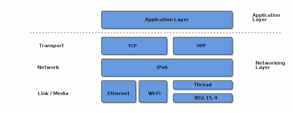
Matter aims to build a universal IPv6-based communication protocol for smart home devices. The protocol defines the application layer that will be deployed on devices as well as the different link layers to help maintain interoperability. The following diagram illustrates the normal operational mode of the stack:
2.2. Layered Architecture
The architecture is divided into layers to help separate the different responsibilities and introduce a good level of encapsulation amongst the various pieces of the protocol stack. The vast majority of interactions flow through the stack captured in the following Figure.
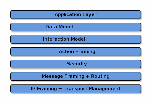
The Application layer corresponds to the high order business logic of a device. For example, an application that is focused on lighting might contain logic to handle turning on/off a light bulb, as well as its color characteristics.
The Data Model layer corresponds to the data and verb elements that help support the functionality of the application. The Application operates on these data structures when there is intent to interact with the device.
The Interaction Model layer defines a set of interactions that can be performed between a client and server device. For example, reading or writing attributes on a server device would correspond to application behavior on the device. These interactions operate on the elements defined at the data model layer.
Once an action is constructed using the Interaction Model, it is serialized into a prescribed packed binary format to encode for network transmission. This process is handled in the Action Framing layer.
An encoded action frame is then processed by the Security Layer: the message is encrypted and appended with a message authentication code. These actions ensure the data remain confidential and authentic between sender and receiver of the message.
With an interaction now serialized, encrypted, and signed, the Message Layer constructs the payload format with required and optional header fields, which specify properties of the message as well logical routing information.
After the final payload has been constructed by the Message Layer, it is sent to the underlying transport protocol (TCP or Matter’s Message Reliability Protocol) for IP management of the data.
Once the data is received on the peer device, it travels up the protocol stack, where the various layers reverse the operations on the data performed by the sender, to finally deliver the message to the Application for consumption.
In addition to the data flows captured above, this specification defines secure session establishment protocols based on operational certificates (see Section 4.13.2, “Certificate Authenticated Session Establishment (CASE)”), or passcodes (see Section 4.13.1, “Passcode-Authenticated Session Establishment (PASE)”), group communication (see Section 4.14, “Group Communication”), a bulk data transfer protocol (BDX) suitable for sending bulk data between Nodes, and provisions for defining manufacturer-specific protocols.
2.3. Network Topology
In principle, any IPv6-bearing network is suitable for Matter deployment, subject to supporting a few core IPv6 standards. In this version of the specification, we focus on three link layer technologies: Ethernet, Wi-Fi and Thread. We restrict the specification to the above so that the specification can suitably cover provisioning of these link layers, and so that the amount of testing in certification is suitably bounded.
Matter treats networks as shared resources: it makes no stipulation of exclusive network ownership or access. As a result, it is possible to overlay multiple Matter networks over the same set of constituent IP networks.
This protocol may operate in the absence of globally routable IPv6 infrastructure. This requirement enables operation in a network disconnected or firewalled from the global Internet. It also enables deployment in situations where the Internet Service Provider either does not support IPv6 on consumer premises or where the support proves otherwise limiting, for example, if the delegated prefix cannot accommodate all the networks and devices on premises.
This protocol supports local communications spanning one or more IPv6 subnets. Canonical networks supporting a fabric may include a Wi-Fi/Ethernet subnet, or one or more low power and lossy networks (LLN) subnets. In this version of the specification, Thread is the supported LLN standard.
2.3.1. Single network
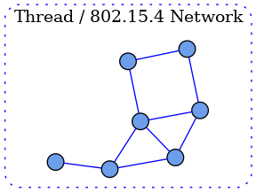
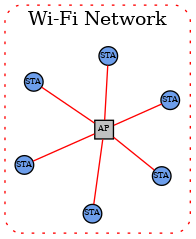
In the single network topology, all Matter devices are connected to a single logical network. This could be a Thread/802.15.4 network, a Wi-Fi network or an Ethernet network. In the case of Wi-Fi/Ethernet, the network could in fact span multiple Wi-Fi and/or Ethernet segments provided that all the segments are bridged at the link layer. A Node is a single instance of a Matter device within a fabric, operationally available on an IP network.
Each Node in the single-network topology communicates with every other Node in the Fabric via a single network interface.
2.3.2. Star network topology
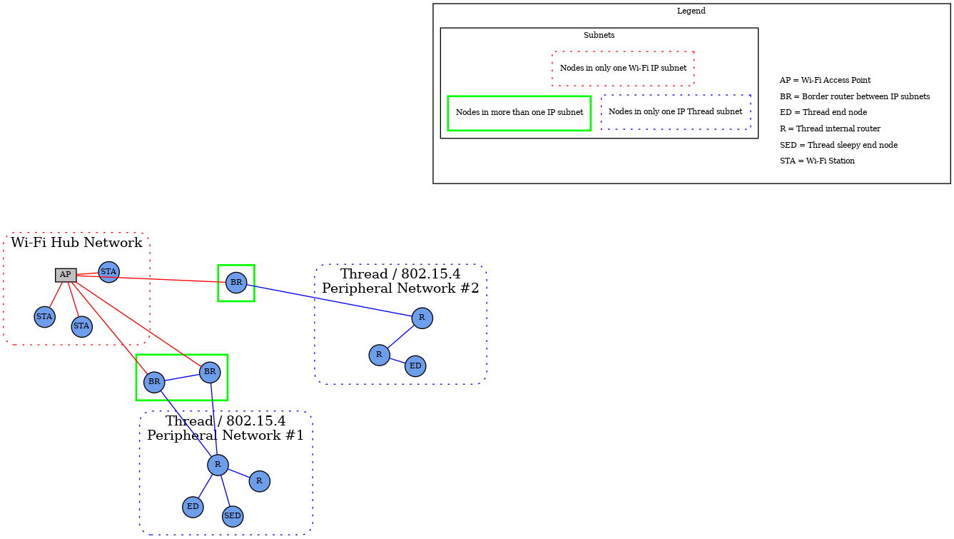
The star network topology consists of multiple peripheral networks joined together by a central hub network. The hub network will typically be the customer’s home network (Wi-Fi/Ethernet network), while the peripheral networks can be of any supported network type. A peripheral network MUST always be joined directly to the hub network via one or more Border Routers.
Architecturally, any number of peripheral networks may be present in a single Fabric, including multiple networks of the same type. Nodes MAY have interfaces onto any network (hub or peripheral), and MAY communicate directly to other Nodes on the same network. However, any communication that must cross a network boundary to reach its destination MUST flow through a Border Router.
This protocol places a set of requirements on the Border Router. These requirements pertain to address assignment, route assignment and advertisement, multicast support, and discovery proxying.
Note that in this version of the specification, Thread is the primary supported LLN. In many cases, customer installations will attempt to maintain a simple network topology, with a single Wi-Fi/Ethernet subnet, and a single Thread network. However, more than one Thread network is possible and supported.
To support home automation interoperability, this protocol supports the concept of bridging which makes available, through a data model node, devices implementing other home automation technologies, transports and link layers.
2.4. Scoped names
The Matter protocol explicitly supports multiple administrators, unrelated by any common roots of trust (multi-admin). This functionality is addressed via multiple fabrics and is enabled by the core aspects of name scoping (see below), and key considerations enabling multiple fabrics in onboarding, secure communication, and aspects of the data model (such as fabric-scoped data).
A Fabric is a collection of Matter devices sharing a trusted root. The root of trust in Matter is the Root CA that issues the NOCs which underpin node identities. Within the fabric, each node is uniquely identified by a stable Node ID. The scoped selection and allocation of these constructs within Matter ensures the uniqueness of identifiers and gives clear guidance on ownership and management of namespaces.
The operational root of trust — the root certificate authority (CA) as identified by its public key (Root PK) — is responsible for the allocation of correctly scoped fabric identifiers. The security of all public key infrastructures (PKI) depends on the private key of the CA being protected and neither guessable nor obtainable; that property, in turn, implies that the public key is globally unique. Within any root CA, the fabrics — identified by a 64-bit number — are unique. The uniqueness mechanism emerges from the collaboration of the commissioner and the root CA associated with that particular commissioner. Matter wraps the collaboration between the commissioner and its associated root CA and other possible data stores into a concept called the "administrative domain manager" (ADM). The algorithmic details and policies within the administrative domain manager are out of the scope of the specification as long as the allocation of all identifiers obeys the uniqueness and scoping criteria. Fabrics are uniquely identified by the tuple of their root CA’s public key and a Fabric ID. Similarly, within each fabric, the administrative domain manager is responsible for assigning a unique and stable Operational Node ID to every node.
The scoping strategy as outlined here ensures that each scoped identifier can be allocated solely by the entities responsible for the scoping, without consideration for collisions or forgeries. For example, two different CAs may allocate the same fabric identifiers and this would not create any problems for the devices within the network. Scoped delegation of responsibility also provides for clear guidelines for the removal of specific identifiers.
A Matter device may be a member of multiple fabrics and thus have multiple associated node IDs. The scoping strategy also naturally lends itself towards unambiguous resolution of names and credentials and places a clearly defined responsibility for managing the namespaces on each fabric’s associated administrative domain manager service.
Prior to the first commissioning, such as in factory-reset state, a typical device contains no pre-allocated operational roots of trust, and no operational identities in the form of fabric IDs and node IDs. Yet, various interactions expect the fabric ID, or a node ID. These identifiers emerge in a number of internal constructs — from address discovery, through identifying secure sessions, to evaluating access control privileges. In order to regularize all interactions with the device and solve the bootstrapping problem, a special primordial fabric ID is reserved, and associates a set of initial access control privileges with any communication that would be associated with the initial commissioning sessions.
2.5. Identifiers
2.5.1. Fabric References and Fabric Identifier
As described above, a Fabric ID is a 64-bit number that uniquely identifies the Fabric within the scope of a particular root CA. Conceptually, the fully qualified fabric reference consists of the tuple containing the public key of the root certificate authority, and the Fabric ID. Because the fully qualified fabric reference is cumbersome to use, a number of mechanisms for compression of the reference are defined. The Fabric reference, in compressed form, is used during operational discovery to provide operational naming separation, a form of namespacing, between unrelated collections of devices.
Fabric ID 0 is reserved across all fabric root public key scopes. This fabric ID SHALL NOT be used as the identifier of a fabric.
A fabric is defined in the Data Model as a set of nodes that interact by accessing Data Model elements as defined in the Interaction Model (see Section 7.5, “Fabric”).
The layers below the data model, that convey data model interactions as messages, SHALL always indicate either the fabric associated with the message, or that there is no fabric associated with the message.
For example: A Data Model message that is conveyed over a message channel that uses the reserved fabric ID '0' does not have a fabric associated with it.
2.5.2. Vendor Identifier (Vendor ID, VID)
A Vendor Identifier (Vendor ID or VID) is a 16-bit number that uniquely identifies a particular product manufacturer, vendor, or group thereof. Each Vendor ID is statically allocated by the Connectivity Standards Alliance (see [CSA Manufacturer Code Database]).
The following Vendor IDs are reserved:
| Range | Type |
|---|---|
0x0000 |
Matter Standard |
0x0001 - 0xFFF0 |
reserved for individual Manufacturer Codes as per CSA Manufacturer Code Database |
0xFFF1 |
Test Vendor #1 |
0xFFF2 |
Test Vendor #2 |
0xFFF3 |
Test Vendor #3 |
0xFFF4 |
Test Vendor #4 |
All other allocations of Vendor ID are specified in CSA Manufacturer Code Database.
|
Note
|
The Test Vendor IDs are reserved for test and development by device manufacturers or hobbyists. Commissioners SHOULD NOT commission devices using one of these VIDs onto an operational Fabric under normal operation unless the user is made fully aware of the security risks of providing an uncertified device with operational and networking credentials. |
2.5.3. Product Identifier (Product ID, PID)
A Product Identifier (Product ID or PID) is a 16-bit number that uniquely identifies a product of a vendor. The Product ID is assigned by the vendor and SHALL be unique for each product within a Vendor ID. Once a Product ID has been used, it SHALL NOT be reused by a different product type under the same Vendor ID. These Product IDs SHOULD NOT be specific to a unique physical device; rather they describe the product type, which might have many manufactured instances (e.g. multiple colors of the same product type).
A value of 0x0000 SHALL NOT be assigned to a product since Product ID = 0x0000 is used for these specific cases:
-
To announce an anonymized Product ID as part of device discovery (see Section 5.4.2, “Announcement by Device”).
-
To indicate an OTA software update file applies to multiple Product IDs equally.
-
To avoid confusion when presenting the Onboarding Payload for ECM with multiple nodes.
2.5.4. Group Identifier (GID)
A Group Identifier (Group ID or GID) is a 16-bit number that identifies a set of Nodes across a Fabric at the message layer (see Section 4.15, “Group Key Management”). A Group ID can further be bound to one or more Endpoints within each Node in the group at the interaction layer.
The Group ID space is allocated as described in Table 2, “Group ID Allocations”:
| Range | Type |
|---|---|
0xFF00 - 0xFFFF |
Universal Group ID range reserved for static multicast and anycast identifiers |
0x0001 - 0xFEFF |
Application Group ID, assigned by fabric Administrator |
0x0000 |
Null or unspecified Group ID |
2.5.4.1. Universal Group ID
A Universal Group ID (UGID) is one that resides in the 16-bit subrange of Group ID that is reserved for groups that are common across this standard. These special multicast, groupcast, or anycast destinations are constant and known to all Nodes on any Fabric. The Universal Group ID space is allocated as described in Table 3, “Universal Group ID Allocations”:
| Range | Type |
|---|---|
0xFFFF |
|
0xFFFE |
|
0xFFFD |
|
0xFF00-0xFFFC |
Reserved for future use |
The Commissioner SHALL configure one or more shared keys for these groups on all Nodes within the Fabric. Because the keys and IPv6 multicast prefixes are different across Fabrics, Universal Groups only enable communication within a specific Fabric.
All non-sleepy Nodes Group
This group is used to message all power-capable Nodes in a Fabric. Sleepy Nodes SHALL NOT subscribe to this group.
All Proxies Group
This group is used to discover Proxy Nodes during Section 9.15.4, “Proxy Subscriptions”.
2.5.5. Node Identifier
A Node Identifier (Node ID) is a 64-bit number that uniquely identifies an individual Node or a group of Nodes on a Fabric. The Node Identifier space is allocated as described in Table 4, “Node Identifier Allocations”:
| Range | Type |
|---|---|
0xFFFF_FFFF_FFFF_xxxx |
Group Node ID |
0xFFFF_FFFF_0000_0000 to 0xFFFF_FFFF_FFFE_FFFF |
Reserved for future use |
0xFFFF_FFFE_xxxx_xxxx |
Temporary Local Node ID |
0xFFFF_FFFD_xxxx_xxxx |
CASE Authenticated Tag |
0xFFFF_FFFC_xxxx_xxxx to 0xFFFF_FFFC_FFFF_FFFF |
Reserved for future use |
0xFFFF_FFFB_xxxx_xxxx |
PAKE key identifiers |
0xFFFF_FFF0_0000_0000 to 0xFFFF_FFFA_FFFF_FFFF |
Reserved for future use |
0x0000_0000_0000_0001 to 0xFFFF_FFEF_FFFF_FFFF |
Operational Node ID |
0x0000_0000_0000_0000 |
Unspecified Node ID |
Node IDs are used for core messaging, within the internal APIs, within the data model, and to resolve the operational IPv6 addresses of Nodes (see Section 4.3.2, “Operational Discovery”).
The span of Node IDs from 0xFFFF_FFF0_0000_0000 to 0xFFFF_FFFF_FFFF_FFFF, as well as the value 0x0000_0000_0000_0000 are both reserved for special uses.
2.5.5.1. Operational Node ID
An Operational Node ID is a 64-bit number that uniquely identifies an individual Node on a Fabric. All messages must have an Operational Node ID as the source address. All unicast messages must have an Operational Node ID as the destination address.
While source or destination address MAY be elided from a message, it MUST remain unambiguously derivable from the Session ID.
2.5.5.2. Group Node ID
A Group Node ID is a 64-bit Node ID that contains a particular Group ID in the lower half of the Node ID.
2.5.5.3. Temporary Local Node ID
A Temporary Local Node ID is a 64-bit Node ID that contains an implementation-dependent value in its lower 32 bits. This allows implementations to keep track of connections or transport-layer links and similar housekeeping internal usage purposes in contexts where an Operational Node ID is unavailable.
2.5.5.4. PAKE key identifiers
This subrange of Node ID is used to assign an access control subject to a particular PAKE key as specified in Section 6.6.2.1.1, “PASE and Group Subjects”. An example usage would be to create an ACL entry to provide administrative access to any commissioner communicating via a PASE session established with a particular pincode.
2.5.5.5. CASE Authenticated Tag
This subrange of Node ID is used to assign an access control subject to a group of peer nodes that share a single CASE session as specified in Section 6.6.2.1.2, “Subjects identified by CASE Authenticated Tag”.
2.5.6. IPv6 Addressing
This protocol uses IPv6 addressing for its operational communication. Node IDs and Fabric IDs are resolved to various types of IPv6 addresses [RFC 4291].
2.5.6.1. IPv6 Unicast Address
An IPv6 Unicast Address is one that uniquely identifies and addresses a single Node on an IPv6 network. A primary design goal for this standard is to allow Nodes to leverage native IPv6 technologies. As such, an operational IPv6 Unicast address that provides connectivity and routability between Nodes SHALL be used. This includes a global unicast address (GUA), a link-local address (LLA), or a unique local address (ULA).
2.5.6.2. IPv6 Multicast Address
An IPv6 Multicast Address is formed using Unicast-Prefix-based IPv6 Multicast Addresses [RFC 3306]:
-
The first 12 bits are defined by [RFC 3306] and are 0xFF3.
-
The next 4 bits are "scop" (scope) and set based on [RFC 7346] Section 2 to:
-
Site-Local (0x5) - spans all networks in the Fabric, including Thread, Ethernet, and Wi-Fi.
-
-
The next 8 bits are reserved (0x00).
-
The next 8 bits are "plen", and set to 0x40 to indicate a 64-bit long network prefix field.
The network prefix portion of the Multicast Address is the 64-bit bitstring formed by concatenating:
-
0xFD to designate a locally assigned ULA prefix per [RFC 4193] Section 3.1
-
The upper 56-bits of the Fabric ID for the network in big-endian order
The 32-bit group identifier portion of the Multicast Address is the 32-bits formed by:
-
The lower 8-bits of the Fabric ID
-
0x00
-
The next 16-bits are the Group Identifier for the group, as specified in Group Identifier in big-endian order
An example of the site local scoped multicast address for a given <Fabric ID> and <Group ID>:
FF35:0040:FD<Fabric ID>00:<Group ID>|
Note
|
though Site-Local scope is always used, the effective scope MAY be limited by setting the IPv6 hop count. |
The Multicast Address formation ensures a low probability of a node receiving a multicast message it is not interested in. If a collision does occur on the multicast address (which requires two identical 64-bit Fabric IDs and two identical 16-bit Group IDs), processing of the message disambiguates which fabric and group is relevant by checking which operational group key leads to the message’s 64-bit MIC.
2.6. Device identity
Each Matter device holds a number of certificate chains.
A Device Attestation Certificate (DAC) proves the authenticity of the manufacturer and a certification status of the device’s hardware and software. The Device Attestation Certificate is used during the commissioning process by the Commissioner to ensure that only trustworthy devices are admitted into a Fabric. The details of the device attestation process are captured in Section 6.2, “Device Attestation”.
Each Matter device is issued an Operational Node ID and a Node Operational Certificate (NOC) for that Operational Node ID. The NOC enables a Node to identify itself within a Fabric by cryptographically binding a unique Node Operational Key Pair to the operational identity of its subject, attestable through the signature of a trusted Certificate Authority (CA). Operational Node IDs are removed on factory reset or removal of Fabrics. A NOC is issued during the commissioning process of a device into a Fabric. These steps help to protect the privacy of the end-user and to adapt to different trust models.
The format of the Node Operational credentials and protocols for generating those credentials are detailed in Section 6.4, “Node Operational Credentials Specification” and Section 6.5, “Operational Certificate Encoding” sections.
2.7. Security
Matter deploys modern security practices to protect the Fabric. Matter designates a core set of security primitives detailed in Chapter 3, Cryptographic Primitives to provide comprehensive protection. Elliptic curve cryptography, based on the NIST P-256 curve (secp256r1) serves as the foundation for public key cryptography and digital signatures. Commonly available AES modes of operation have been selected to provide shared key cryptographic operations. In scenarios involving an out-of-band passcode-based authentication, Matter uses SPAKE2+, an efficient augmented PAKE algorithm.
The core cryptographic primitives form the basis of a number of complementary secure protocols used within Matter. All unicast Node-to-Node messages are secured, authenticated, and provide replay protection. Building on top of IPv6 multicast, Matter also provides group messaging facilities, useful for efficiently addressing on an LLN. The group messaging features prioritize low latency of packet processing.
2.8. Device Commissioning
Device commissioning (see Chapter 5, Commissioning) is the process of joining a device to a Fabric. The device being commissioned is referred to as the Commissionee and the device administering commissioning is referred to as the Commissioner. Device commissioning consists of the following steps:
-
Device discovery (see Section 5.4, “Device Discovery” and see Section 5.1, “Onboarding Payload”): The Commissioner discovers commissionable devices on network interfaces such as Bluetooth Low Energy, Wi-Fi, or other connected IP network. The Commissioner obtains the out-of-band secret (Passcode) from the commissionable device’s QR Code, Manual Pairing Code, NFC Tag or other means. This secret is used by Passcode-Authenticated Session Establishment (PASE) to establish a secure commissioning session. The order of discovering commissionable devices and obtaining the out-of-band secret from commissionable device is not critical.
-
Security setup with PASE (see Section 4.13.1, “Passcode-Authenticated Session Establishment (PASE)”): Establish encryption keys between the Commissioner and Commissionee using PASE. All messages exchanged between the Commissioner and Commissionee are encrypted using these PASE-derived keys. The process also establishes an attestation challenge used during the device attestation procedure.
-
Device attestation verification (see Section 6.2, “Device Attestation”): Commissioner establishes the authenticity of the Commissionee as a certified device, notifying the user if the device is not certified.
-
Information configuration (see Section 6.4, “Node Operational Credentials Specification”, Section 11.9, “General Commissioning Cluster” and Section 11.17, “Node Operational Credentials Cluster”): The Commissioner provides Commissionee with information such as regulatory domain, UTC time, Operational Certificate and network interfaces configuration.
-
Join network (see Section 11.8, “Network Commissioning Cluster” and Section 4.3.2, “Operational Discovery”): The Commissioner triggers the Commissionee to connect to the operational network unless the Commissionee is already on the operational network. The Node’s/Commissionee’s IPv6 address is then either used (if already known) or discovered (if not known) by the Commissioner or Administrator.
-
Security setup with CASE (see Section 4.13.2, “Certificate Authenticated Session Establishment (CASE)”): Derive encryption keys used to establish secure communication between the Commissioner or Administrator and Node with CASE. All unicast messages between a Commissioner or Administrator and a Node are encrypted using these CASE-derived keys.
-
Commissioning complete message exchange (see Section 11.9, “General Commissioning Cluster”): A message exchange encrypted using CASE-derived encryption keys on the operational network that indicates successful completion of commissioning process.
A commissioner can reconfigure the Commissionee multiple times over the operational network after the commissioning is complete or over the commissioning channel after PASE-derived encryption keys are established during commissioning. The commissioning flows are described in Section 5.5, “Commissioning Flows”.
2.9. Sleepy End Device (SED)
One goal of this standard is to provide support for low energy Nodes running on limited power sources such as batteries or limited energy scavenging. The Sleepy End Device (SED) operating mode is defined to help extend and optimize battery lifetimes for such Nodes. The SED operating mode mirrors and aligns with Thread SED behavior, but may be leveraged over other supported IP interfaces, including Wi-Fi. The steady state behavior of a SED Node is to disable its IP interface (and underlying radio or link technology). A SED then periodically wakes to communicate with some infrastructure device in order to participate on the network. In the case of a Thread network (see [Thread specification]]), the infrastructure device is a parent Thread Router. For Wi-Fi, the access point provides the required infrastructure support. Two intervals are defined:
-
Idle mode, or slow-polling, sets the maximum time a SED will sleep before polling. This parameter affects both the minimum power consumption and maximum latency. The SLEEPY_IDLE_INTERVAL parameter communicates the maximum sleep interval of a node in idle mode.
-
Active mode sets the SED into a fast-polling interval for maximum responsiveness when the Node is engaged in ongoing communication, such as an active Exchange. The SLEEPY_ACTIVE_INTERVAL parameter communicates the maximum sleep interval of a node in active mode.
A SED SHALL indicate it is a sleepy device to peer nodes by setting its SLEEPY_IDLE_INTERVAL to a value greater than the default and advertising that value per [Discovery_SII].
|
Note
|
Because parent infrastructure devices have limited buffering space to cache messages on behalf of sleepy devices, SED communication patterns SHOULD be designed such that the SED is predominantly the initiator. |
A Node determines whether it is in Active or Idle mode based on whether it has any outstanding Exchanges in the Message Layer. While there are Exchanges active, a node will remain in Active mode and poll at the fast-polling interval if it is a SED. Once all Exchanges are closed, a node SHOULD transition into Idle mode and poll at the slow-polling interval if it is a SED and the node has no other outstanding reasons for staying awake.
2.10. Data Model Root
-
Endpoint 0 (zero) SHALL be the root node endpoint.
-
Endpoint 0 (zero) SHALL support the Root Node device type.
2.11. Stack Limits
2.11.1. System Model Limits
2.11.1.1. Access Control Limits
-
A node SHALL guarantee that there are at least three Access Control Entries available for every fabric supported by the node.
-
Device types MAY impose additional constraints on the number of ACL entries that need to be supported.
2.11.1.2. Group Limits
-
A node SHALL support at least one group key per fabric for managing the IPK.
-
If the node implements one or more device types with support for the Groups cluster, the node SHALL additionally support the maximum number of the required groups as specified by all of these implemented device types.
-
A node SHALL support one IPv6 multicast group membership for every operational group it supports.
-
Support for GroupKeyMulticastPolicy field in GroupKeySetStruct is provisional.
2.11.2. Interaction Model Limits
2.11.2.1. Read Interaction Limits
-
A server SHALL ensure that every fabric the node is commissioned into can handle a single Read Interaction from a client on that fabric containing up to 9 paths.
-
A server MAY permit Read Interactions even when there is no accessing fabric, subject to available resources (e.g over PASE).
2.11.2.2. Subscribe Interaction Limits
-
A publisher SHALL ensure that every fabric the node is commissioned into can support at least three Subscribe Interactions to the publisher and that each subscription SHALL support at least 3 attribute/event paths.
-
A server MAY permit Subscribe Interactions even when there is no accessing fabric, subject to available resources (e.g over PASE).
-
Device type specifications MAY require a larger number of supported subscriptions or paths.
-
SUBSCRIPTION_MAX_INTERVAL_PUBLISHER_LIMITdefines the upper limit for the publisher-selected maximum interval for any subscription. This SHALL be set to 60 minutes. -
The minimal supported capabilities, subject to the minimal constraints above, are reported in the CapabilityMinima attribute of the Basic Information cluster.
2.11.2.3. Invoke Interaction Limits
-
An Invoke Request action SHALL be limited to a single concrete command path.
2.12. List of Provisional Items
The following is a list of provisional items.
2.12.1. Invoke Multiple Paths
-
Support for an Invoke Interaction with multiple paths or wildcard paths is provisional.
2.12.3. Proxy Service
The Proxy Architecture, the Proxy Config and Proxy Discovery clusters are provisional.
2.12.4. Time Synchronization
The Time Synchronization feature is provisional.
2.12.5. Parameters and Constants
Table 5, “Glossary of parameters” is a glossary of parameters used in this chapter with a brief description for each parameter. A Node SHALL use the provided default value for each parameter unless the message recipient Node advertises an alternate value for the parameter via Operational Discovery.
| Parameter Name | Description | Default Value |
|---|---|---|
SLEEPY_IDLE_INTERVAL |
Maximum sleep interval of node when in idle mode. |
300 milliseconds |
SLEEPY_ACTIVE_INTERVAL |
Maximum sleep interval of node when in active mode. |
300 milliseconds |
SLEEPY_ACTIVE_THRESHOLD |
Minimum amount the node SHOULD stay awake after network activity. |
4000 milliseconds |
These parameters are encoded in the following TLV format when included in CASE / PASE session establishment:
sed-parameter-struct => STRUCTURE [ tag-order ]
{
SLEEPY_IDLE_INTERVAL [1, optional] : UNSIGNED INTEGER [ range 32-bits ],
SLEEPY_ACTIVE_INTERVAL [2, optional] : UNSIGNED INTEGER [ range 32-bits ],
}
3. Cryptographic Primitives
This chapter introduces the various cryptographic primitives, algorithms and protocol building blocks used in this protocol. It introduces for each of them a functional abstraction that can be referred to in the other chapters of this specification. This chapter also maps those cryptographic primitives to specific instances with the corresponding appropriate informative or normative references. Wherever relevant, it also gives necessary or relevant information about the use of these mappings in a specific context to achieve a compliant implementation.
Given a version of the Message Format, the cryptographic primitives are mapped to specific instances. There is no cryptosuite negotiation in this protocol: one version of the Message Format has one cryptosuite as defined in this chapter.
Each section defines cryptographic primitives generically, together with concrete mappings to specific instances of these cryptographic primitives for version 1.0 of the Message Format. This chapter can also be used as guidance about which cryptographic primitives need to be supported by a device, but it must be noted that not all devices will have to support all of them. For example, a device may not require the Crypto_PBKDF() primitive, as values based on this operation could in some instances be precomputed and stored during the manufacturing process of the device. The proposed functional mapping in this chapter is normative with respect to the values computed by the functions but informative with respect to the way the functions are interfaced within implementations. For example, a function returning both a boolean to indicate success and a value if the operation is successful could also be implemented using exception mechanisms instead of returning a boolean.
It must also be noted that not all cryptographic primitives are exposed to the other parts of the specification. For example, the Crypto_TRNG() primitive SHALL NOT be called outside of the Crypto_DRBG() implementation.
The cryptographic primitives discussed below operate on data local to the host. Where more complex data types are present and their external representation is applicable, the chapter notes the details of the encoding. Simple multi-byte data types without any additional context are assumed to be in host byte order when they are used internally to a procedure, unless otherwise stated.
All octet strings are presented with first octet having index 0, and presented from left to right for indices 0 through N-1 for an octet string of length N.
3.1. Deterministic Random Bit Generator (DRBG)
This protocol relies on random numbers for many security purposes. For example, random numbers are used in generating secret keys, counters, cryptographic signature generation random secrets, etc. Those random numbers SHALL be generated using the Crypto_DRBG() function.
| Function and description |
|---|
bit[len] Crypto_DRBG(int len) Returns an array of |
| Mapping (Version 1.0) |
|---|
|
3.2. True Random Number Generator (TRNG)
A TRNG (aka. Entropy Source) is required to provide an entropy seed as an input to the DRBG algorithm.
| Function and description |
|---|
bit[len] Crypto_TRNG(int len) Returns an array of |
| Mapping (Version 1.0) |
|---|
|
In accordance with good security practices, the Crypto_TRNG() SHALL never be called directly but rather SHALL be used in the implementation of Crypto_DRBG().
3.3. Hash function (Hash)
Crypto_Hash() computes the cryptographic hash of a message.
| Function and description |
|---|
byte[CRYPTO_HASH_LEN_IN_BYTES] Crypto_Hash(byte[] message) Returns the cryptographic hash digest of the |
| Mapping (Version 1.0) |
|---|
|
|
|
Crypto_Hash(message) :=
byte[CRYPTO_HASH_LEN_BYTES] SHA-256(M := message)
|
3.4. Keyed-Hash Message Authentication Code (HMAC)
Crypto_HMAC() computes the cryptographic keyed-hash message authentication code of a message.
| Function and description |
|---|
byte[CRYPTO_HASH_LEN_BYTES] Crypto_HMAC(byte[] key, byte[] message) Returns the cryptographic keyed-hash message authentication code of a |
| Mapping (Version 1.0) |
|---|
Crypto_HMAC(key, message) :=
byte[CRYPTO_HASH_LEN_BYTES] HMAC(K := key, text := message)
|
3.5. Public Key Cryptography
Matter specifies the following scheme and parameters for public key cryptography.
3.5.1. Group
The public key cryptography of Matter relies on the group defined in the following mapping table.
| Mapping (Version 1.0) |
|---|
Matter public key cryptography SHALL be based on Elliptic Curve Cryptography (ECC) with the elliptic curve: |
|
|
|
|
|
struct {
PublicKey publicKey;
PrivateKey privateKey;
} KeyPair;
|
3.5.2. Key generation
Crypto_GenerateKeyPair() is the function to generate a key pair.
| Function and description |
|---|
KeyPair Crypto_GenerateKeyPair() Generates a key pair and returns a |
| Mapping (Version 1.0) |
|---|
Crypto_GenerateKeypair() :=
KeyPair ECCGenerateKeypair()
|
3.5.3. Signature and verification
Crypto_Sign() is used to sign a message, and Crypto_Verify() is used to verify a signature on a message.
These functions either generate or verify a signature of type Signature defined by the following mapping.
| Mapping (Version 1.0) |
|---|
struct {
byte[CRYPTO_GROUP_SIZE_BYTES] r,
byte[CRYPTO_GROUP_SIZE_BYTES] s
} Signature
|
3.5.3.1. Signature
| Function and description |
|---|
Signature
Crypto_Sign(
PrivateKey privateKey,
byte[] message)
Returns the signature of the |
| Mapping (Version 1.0) |
|---|
Crypto_Sign(privateKey, message) :=
Signature ECDSASign(dU := privateKey, M := message)
|
3.5.3.2. Signature verification
| Function and description |
|---|
boolean
Crypto_Verify(
PublicKey publicKey,
byte[] message,
Signature signature)
Verifies the |
| Mapping (Version 1.0) |
|---|
Crypto_Verify(publicKey, message, signature) :=
boolean ECDSAVerify(QU := publicKey, M := message, S := signature)
|
3.5.4. ECDH
Crypto_ECDH() is used to compute a shared secret from the Elliptic Curve Diffie-Hellman (ECDH) protocol.
| Function and description |
|---|
byte[CRYPTO_GROUP_SIZE_BYTES]
Crypto_ECDH(
PrivateKey myPrivateKey,
PublicKey theirPublicKey)
Computes a shared secret using Elliptic Curve Diffie-Hellman. |
| Mapping (Version 1.0) |
|---|
Crypto_ECDH(myPrivateKey, theirPublicKey) :=
byte[CRYPTO_GROUP_SIZE_BYTES] ECDH(dU := myPrivateKey, QV := theirPublicKey)
The output of |
3.5.5. Certificate validation
Crypto_VerifyChain() is used to verify Matter certificates.
Crypto_VerifyChainDER() is used to verify public key X.509 v3 certificates in X.509 v3 DER format.
| Function and description |
|---|
boolean Crypto_VerifyChain(MatterCertificate[] certificates) Given Matter certificates, |
boolean Crypto_VerifyChainDER(DERCertificate[] certificates) Given a list of DER-encoded certificates in RFC 5280 format, starting at the end-entity (leaf) certificate, and following the chain of trust towards the root, |
| Mapping (Version 1.0) |
|---|
Crypto_VerifyChain(certificates) :=
boolean verified
|
Crypto_VerifyChainDER(certificates) :=
boolean verified
|
The primitives as described above verify cryptographic integrity of the certificate chains. This specification imposes a number of additional constraints on certificates discussed below in sections on Device Attestation Certificates, Node Operational Certificates and Certificate Common Conventions.
3.5.6. Time and date considerations for certificate path validation
The Basic Path Validation algorithm in RFC 5280 mandates the consideration of the "current time" against the validity period (notBefore, notAfter fields) when validating paths. The usage of "current time" assumes that such a time is available and correct, which is a strong assumption when considering some constrained devices or devices only locally reachable on a network in the absence of infrastructure to synchronize time against a global real-time reference.
When the Crypto_VerifyChain primitive is used, rather than overriding the Basic Path Validation algorithm of RFC 5280, Nodes SHALL consider the following definition of "current time" that accounts for the possible lack of a real time reference:
-
If a Node has a current real-time clock value which is trusted according to implementation-defined means to be accurate with regard to global real-time, whether using Time Synchronization features of this specification or other means, then it SHALL use that time;
-
Otherwise, the current time SHALL be set to the last-known-good UTC time.
Upon failure to validate a certificate path, where the only reason for failure is an invalid validity period of a path element, a Node MAY apply a policy of its choice to determine whether to ignore this failure and still consider the path valid.
3.5.6.1. Last Known Good UTC Time
Nodes SHALL maintain a stored Last Known Good UTC Time. This time is used as a fallback for cryptographic credentials expiry enforcement, if all other available time synchronization mechanisms fail.
The last known good UTC time SHALL be updated at commissioning and MAY be updated after a successful time synchronization, or by an embedded time in an OTA. Nodes SHOULD store a Last Known Good UTC Time value to persistent storage at least once a month. A Node’s initial out-of-box Last Known Good UTC time SHALL be the compile-time of the firmware.
A Node MAY adjust the Last Known Good UTC Time backwards if it believes the current Last Known Good UTC Time is incorrect and it has a good time value from a trusted source. The Node SHOULD NOT adjust the Last Known Good UTC to a time before the later of:
-
The build timestamp of its currently running software image
-
The not-before timestamp of any of its operational certificates (see Section 6.4.5, “Node Operational Credentials Certificates”).
If a Node has used the Last Known Good UTC Time, it SHOULD recheck its security materials and existing connections if it later achieves time synchronization.
3.6. Data Confidentiality and Integrity
Symmetric block ciphers are used to provide message security.
All unicast and multicast messages between Nodes requiring protection for confidentiality and integrity with data origin authentication SHALL use Authenticated Encryption with Associated Data (AEAD) as primitive to protect those messages.
| Mapping (Version 1.0) |
|---|
Data confidentiality and integrity SHALL use the AES-CCM mode as defined in NIST 800-38C with the following parameters:
|
|
3.6.1. Generate and encrypt
| Function and description |
|---|
byte[lengthInBytes(P) + CRYPTO_AEAD_MIC_LENGTH_BYTES]
Crypto_AEAD_GenerateEncrypt(
SymmetricKey K,
byte[lengthInBytes(P)] P,
byte[] A,
byte[CRYPTO_AEAD_NONCE_LENGTH_BYTES] N)
Performs the generate and encrypt computation on payload |
| Mapping (Version 1.0) |
|---|
Crypto_AEAD_GenerateEncrypt(K, P, A, N) :=
byte[lengthInBytes(P) + CRYPTO_AEAD_MIC_LENGTH_BYTES] AES-CCM-GenerateEncrypt(K := K, P := P, A := A, N := N, Tlen := CRYPTO_AEAD_MIC_LENGTH_BITS)
|
3.6.2. Decrypt and verify
| Function and description |
|---|
{boolean success, byte[lengthInBytes(P)] payload}
Crypto_AEAD_DecryptVerify(
SymmetricKey K,
byte[lengthInBytes(P) + CRYPTO_AEAD_MIC_LENGTH_BYTES] C,
byte[] A,
byte[CRYPTO_AEAD_NONCE_LENGTH_BYTES] N)
Performs the decrypt and verify computation on the combined ciphertext and tag This function has two outcomes:
|
| Mapping (Version 1.0) |
|---|
Crypto_AEAD_DecryptVerify(K, C, A, N) :=
{boolean, byte[lengthInBytes(P)]} AES-CCM-DecryptVerify(K := K, C := C, A := A, N := N, Tlen := CRYPTO_AEAD_MIC_LENGTH_BITS)
|
3.7. Message privacy
Message privacy is implemented using a block cipher in CTR mode.
| Mapping (Version 1.0) |
|---|
Message privacy SHALL use the AES-CTR mode as defined in NIST 800-38A with the following parameters:
|
3.7.1. Privacy encryption
| Function and description |
|---|
byte[lengthInBytes(M)]
Crypto_Privacy_Encrypt(
SymmetricKey K,
byte[lengthInBytes(M)] M,
byte[CRYPTO_PRIVACY_NONCE_LENGTH_BYTES] N)
Performs the encryption of the message |
| Mapping (Version 1.0) |
|---|
Crypto_Privacy_Encrypt(K, M, N) :=
byte[lengthInBytes(M)]
AES-CTR-Encrypt(K := K, P := M, N := N)
|
3.7.2. Privacy decryption
| Function and description |
|---|
byte[lengthInBytes(C)]
Crypto_Privacy_Decrypt(
SymmetricKey K,
byte[lengthInBytes(C)] C,
byte[CRYPTO_PRIVACY_NONCE_LENGTH_BYTES] N)
Performs the decryption of |
| Mapping (Version 1.0) |
|---|
Crypto_Privacy_Decrypt(K, C, N) :=
byte[lengthInBytes(C)]
AES-CTR-Decrypt(K := K, C := C, N := N)
|
3.8. Key Derivation Function (KDF)
Matter specifies the following key derivation function to generate encryption keys.
| Function and description |
|---|
bit[len]
Crypto_KDF(
byte[] inputKey,
byte[] salt,
byte[] info,
int len)
Returns the key of |
| Mapping (Version 1.0) |
|---|
Crypto_KDF(inputKey, salt, info, len) :=
bit[len] KDM(Z := inputKey, OtherInput := {salt := salt, L := len, FixedInfo := info})
|
When multiple keys of the same length are generated by a single KDF call, the following shorthand notation can be used:
Key1 || Key2 || Key3 = Crypto_KDF
(
inputKey = inputKeyMaterial,
salt = [],
info = [],
// 3 below matches number of keys expressed in concatenated output
len = 3 * CRYPTO_SYMMETRIC_KEY_LENGTH_BITS
)
This is equivalent to the following:
Keys = Crypto_KDF
(
inputKey = inputKeyMaterial,
salt = [],
info = [],
len = 3 * CRYPTO_SYMMETRIC_KEY_LENGTH_BITS
)
-
Set
Key1to theCRYPTO_SYMMETRIC_KEY_LENGTH_BITSmost significant bits ofKeys. -
Set
Key2to the nextCRYPTO_SYMMETRIC_KEY_LENGTH_BITSsignificant bits ofKeys. -
Set
Key3to theCRYPTO_SYMMETRIC_KEY_LENGTH_BITSleast significant bits ofKeys.
3.9. Password-Based Key Derivation Function (PBKDF)
Matter specifies the following password-based key derivation function to compute a derived key from a cryptographically weak password.
| Function and description |
|---|
bit[len]
Crypto_PBKDF(
byte[] input,
byte[] salt,
int iterations,
int len)
Returns a value of |
| Type and description |
|---|
STRUCTURE Crypto_PBKDFParameterSet Maintains the set of parameters exchanged between a Commissioner and a Commissionee during their pairing. |
| Mapping (Version 1.0) |
|---|
|
|
Crypto_PBKDF(input, salt, iterations, len) :=
bit[len] PBKDF2(P := input, S := salt, C := iterations, kLen := len)
|
Crypto_PBKDFParameterSet => STRUCTURE [ tag-order ]
{
iterations [1] : UNSIGNED INTEGER [ range 32-bits ],
salt [2] : OCTET STRING [ length 16..32 ],
}
|
3.10. Password-Authenticated Key Exchange (PAKE)
This protocol uses password-authenticated key exchange (PAKE) for the PASE protocol.
| Mapping (Version 1.0) |
|---|
Matter uses SPAKE2+ as described in SPAKE2+ as PAKE with:
|
CRYPTO_W_SIZE_BYTES := CRYPTO_GROUP_SIZE_BYTES + 8
CRYPTO_W_SIZE_BITS := CRYPTO_W_SIZE_BYTES * 8
byte w0s[CRYPTO_W_SIZE_BYTES] || byte w1s[CRYPTO_W_SIZE_BYTES] =
(byte[2 * CRYPTO_W_SIZE_BYTES])
bit[2 * CRYPTO_W_SIZE_BITS]
Crypto_PBKDF(passcode, salt, iterations, 2 * CRYPTO_W_SIZE_BITS)
byte w0[CRYPTO_GROUP_SIZE_BYTES] = w0s mod p
byte w1[CRYPTO_GROUP_SIZE_BYTES] = w1s mod p
where:
|
byte w0s[CRYPTO_W_SIZE_BYTES] || byte w1s[CRYPTO_W_SIZE_BYTES] =
(byte[2 * CRYPTO_W_SIZE_BYTES])
bit[2 * CRYPTO_W_SIZE_BITS]
Crypto_PBKDF(passcode, salt, iterations, 2 * CRYPTO_W_SIZE_BITS)
byte w0[CRYPTO_GROUP_SIZE_BYTES] = w0s mod p
byte w1[CRYPTO_GROUP_SIZE_BYTES] = w1s mod p
byte L[CRYPTO_PUBLIC_KEY_SIZE_BYTES] = w1 * P
where:
|
3.10.3. Computation of transcript TT
| Mapping (Version 1.0) |
|---|
Crypto_Transcript(PBKDFParamRequest, PBKDFParamResponse, pA, pB) :=
byte[] TT
Context := Crypto_Hash("Matter PAKE V1 Commissioning" || PBKDFParamRequest || PBKDFParamResponse)
TT :=
lengthInBytes(Context) || Context ||
0x0000000000000000 || 0x0000000000000000 ||
lengthInBytes(M) || M ||
lengthInBytes(N) || N ||
lengthInBytes(pA) || pA ||
lengthInBytes(pB) || pB ||
lengthInBytes(Z) || Z ||
lengthInBytes(V) || V ||
lengthInBytes(w0) || w0
Note the two Note in case |
3.10.4. Computation of cA, cB and Ke
| Mapping (Version 1.0) |
|---|
Crypto_P2(TT, pA, pB) :=
{byte cA[CRYPTO_HASH_LEN_BYTES],
byte cB[CRYPTO_HASH_LEN_BYTES],
byte Ke[CRYPTO_HASH_LEN_BYTES/2]}
|
4. Secure Channel
4.1. General Description
The Secure Channel and Message Layer provides a consistent networking service substrate to allow Nodes to communicate securely with one another.
During commissioning and unicast communication, a discovery mechanism is provided to determine peer IPv6 addresses and operational parameters. Secure session establishment mechanisms are provided using either certificates (CASE) or shared passcodes (PASE).
4.1.1. Messages
Communication is performed using messages. Messages are either secured or unsecured.
Each message has a Session Type and Session ID in order to identify whether it is secured and how it is to be decrypted and authenticated if it is. Each message has a Message Counter field in order to uniquely identify the message for the purposes of security and duplicate detection.
Operational communication is defined as traffic that uses the secured Matter message format between commissioned nodes over an IP transport. All operational communication has message security enabled. Operational communication between Nodes can be either unicast or multicast.
Unsecured communication is strictly limited to:
-
Discovery, which does not use the Matter message format.
-
User Directed Commissioning (UDC), which uses unsecured messages to initiate the commissioning process.
-
Session establishment, which uses unsecured messages to establish a CASE or PASE session.
4.1.1.1. Message Types
Messages are defined as either a control message or data message. Most messages are data messages. Control messages are reserved for internal protocols such as MCSP to initialize security. Both message types are identical in format, but use separate message counter domains so they can operate securely over the same security key.
4.1.1.2. Message Transports
Messages are of finite size and are sent as individual packets over the supported transports:
-
UDP transports each message as a separate datagram. Messages support a basic reliability protocol called MRP for use when the underlying transport (in this case UDP) doesn’t provide such features.
-
TCP transports each message with a length prepended, performing segmentation and reassembly as needed.
-
BTP transports each message over BLE as a separate SDU, performing segmentation and reassembly as needed.
BTP is provided as a transport protocol for commissioning. TCP and MRP (UDP with added reliability) are provided as transport protocols for operational messaging.
4.1.1.3. Message Exchanges
Messages provide an Exchange Layer to track related messages that make up small, discrete transactions. The Exchange Layer provides this transaction tracking facility to the Interaction Model Layer above, providing a means to multiplex multiple such concurrent transactions over a given underlying session. The Exchange Layer also integrates the Message Reliability Protocol (MRP) as a service for use over UDP transports. This Message Layer architecture is shown below in Figure 6, “Message Layer Stack”:
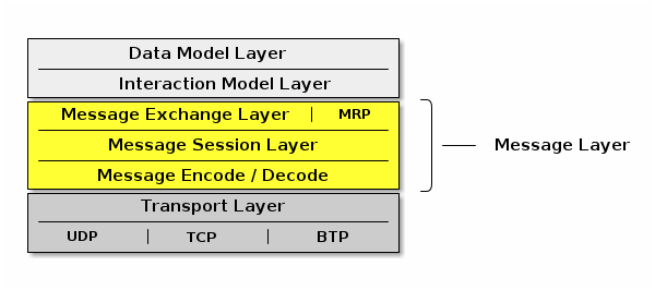
4.2. IPv6 Reachability
This section describes IPv6 network configuration requirements to enable IPv6 reachability between Nodes. As described in Section 2.3, “Network Topology”, a Matter network may be composed of one or more IPv6 networks.
In a single network configuration, all Matter Nodes are attached to the same IPv6 link. A single network configuration may consist of a single bridged Wi-Fi / Ethernet network where all nodes attached to that network are part of the same broadcast domain. When all Matter Nodes are attached to the same Wi-Fi / Ethernet network, link-local IPv6 addressing is sufficient - no additional IPv6 network infrastructure is required.
In a multiple network configuration, a Matter network is composed of (typically one) infrastructure network and one or more stub networks. Unlike an infrastructure network, stub networks do not serve as transit networks. Typically, the infrastructure network is a bridged Wi-Fi / Ethernet network and the Thread networks are stub networks. A stub router connects a stub network to an infrastructure network and provides IPv6 reachability between the two networks.
4.2.1. Stub Router Behavior
A stub router SHALL implement [draft-lemon-stub-networks]. In a multiple network configuration, both the infrastructure and stub networks require routable IPv6 addresses to communicate across networks. A routable IPv6 address SHALL have global scope (e.g. GUA or ULA) [RFC 4007] and SHALL be constructed out of a prefix advertised as on-link. If there is no routable prefix on a given network, the stub router SHALL provide its own routable prefix. Note that Thread’s "on-mesh prefix" is equivalent to Wi-Fi / Ethernet’s "on-link prefix".
Stub routers SHALL advertise reachability to all routable prefixes on the adjacent network. A stub router connecting a Thread network SHALL advertise reachability to all of the Thread network’s routable prefixes to the adjacent infrastructure network using Route Information Options [RFC 4191] contained in Router Advertisements [RFC 4861]. That same stub router SHALL also advertise reachability to all of the infrastructure network’s routable prefixes to the adjacent Thread network in the Thread Network Data [Thread specification].
4.2.2. Matter Node Behavior
Matter Nodes SHALL configure a link-local IPv6 address. In addition, Nodes SHALL support configuration of at least three routable IPv6 addresses (in addition to the link-local and, in the case of Thread, mesh-local addresses). On a Wi-Fi / Ethernet interface, ICMPv6 Router Advertisement (RA) messages advertise prefixes for use on the link [RFC 4861]. On a Thread interface, the Thread Network Data contains prefixes for use on the link [Thread specification]. If a Node receives an on-link prefix that allows autonomous configuration on a given interface and the Node has fewer than three routable IPv6 addresses configured, the Node SHALL autonomously configure an IPv6 address out of that prefix.
Matter Nodes SHALL also configure routes to adjacent networks. On Wi-Fi / Ethernet networks, Nodes SHALL process Route Information Options [RFC 4191] and configure routes to IPv6 prefixes assigned to stub networks via stub routers. Wi-Fi / Ethernet interfaces SHALL support maintaining at least 16 different routes configured using Route Information Options. On Thread networks, Nodes SHALL route according to routing information provided in the Thread Network Data [Thread specification]. Thread devices SHALL support as many routes as can be encoded in the Thread Network Data.
Matter Nodes SHALL support a number of IPv6 neighbor cache entries at least as large as the number of supported CASE sessions plus the number of supported routes.
4.3. Discovery
This section describes Service Advertising and Discovery for Matter.
Service Advertising and Discovery is used within Matter in the following contexts:
-
Commissionable Node Discovery
-
Operational Discovery
-
Commissioner Discovery
-
User Directed Commissioning
Service Advertising and Discovery for Matter uses IETF Standard DNS-Based Service Discovery (DNS‑SD) [RFC 6763]. Matter requires no modifications to IETF Standard DNS‑SD.
Using DNS‑SD means that both the unicast IPv6 address and port of the offered service are discovered, freeing Matter from requiring a single preallocated fixed port. This also makes it possible to run multiple instances of Matter software on a single device, because each instance has its own dynamically allocated port, instead of conflicting over attempting to use the same preallocated fixed port.
On Wi‑Fi and Ethernet networks today, DNS‑SD [RFC 6763] uses Multicast DNS [RFC 6762] for zero-configuration operation.
Since Matter protocols must support IPv6 at a minimum, Matter software discovering other Matter instances SHALL process DNS AAAA (IPv6 address) records, but also MAY process DNS A (IPv4 address) records.
Because of this, where feasible in the underlying service discovery API, Matter software advertising the availability of a service SHOULD indicate that announcements and answers for this service need include only IPv6 address records, not IPv4 address records. On a general-purpose dual-stack host that supports both IPv4 and IPv6, this can be achieved by having Matter-related SRV records reference a Matter-specific target hostname that has only IPv6 address records attached. This allows a general-purpose dual-stack host to offer discoverable IPv4 addresses for legacy client software that still requires IPv4, while offering optimized IPv6-only address discovery for Matter purposes.
Similarly, since Matter does not use IPv4, Matter software discovering other Matter instances SHOULD NOT expect any IPv4 addresses included in responses.
These two items address the content of service discovery messages. When using Multicast DNS similar efficiency questions arise related to the delivery of those service discovery messages, sent over IPv4, IPv6, or both.
Where supported in the underlying service discovery API, Matter software using Multicast DNS to advertise the availability of a service SHOULD indicate that announcements and answers for this service need only be performed over IPv6.
Similarly, where supported in the underlying service discovery API, Matter application software using Multicast DNS to issue service discovery queries SHOULD indicate that these queries need only be performed over IPv6.
These optimizations reduce both the size and the number of multicast packets, which is particularly beneficial on Wi‑Fi networks. A Matter device that only supports IPv6 gets these optimizations automatically, simply by virtue of not supporting IPv4 at all.
For Thread mesh networks, where excessive use of multicast would be detrimental [RFC 7558], DNS‑SD uses Unicast DNS instead, leveraging capabilities of the Thread Service Registry on the Thread Border Router [draft-lemon-stub-networks].
Conceptually, the DNS‑SD [RFC 6763] information being communicated is identical to when Multicast DNS [RFC 6762] is being used, except that the information is communicated in unicast packets to and from a designated Service Registry, rather than being communicated in multicast packets to and from every other node in the same broadcast domain.
Using Service Registration Protocol [SRP] and an Advertising Proxy [AdProx] running on the Thread Border Router, Matter Nodes on a Thread mesh can be discovered by other Matter Nodes on an adjacent Ethernet or Wi‑Fi link, without the cost of using multicast on the Thread mesh. All Thread-connected Matter Nodes SHALL implement Service Registration Protocol.
Thread Border Routers advertise available SRP servers in the Thread Network Data [Thread specification]. Thread devices SHALL register their services using an available SRP server [Thread specification].
When Matter Nodes issue short-lived requests to other Matter Nodes, the response is sent back to the source IPv6 address and port of the request. When Matter Nodes issue long-lived requests to other Matter Nodes, by the time the response is generated the requester may have changed IPv6 address or port, so the responder may have to discover the current IPv6 address and port of the initiator in order to send the response.
A Thread Border Router SHALL implement DNS‑SD Discovery Proxy [RFC 8766] to enable clients on the Thread mesh (e.g., other Nodes) to discover services (e.g., Matter Nodes) advertised using Multicast DNS on an adjacent Ethernet or Wi‑Fi link, also without the cost of using multicast on the Thread mesh [draft-lemon-stub-networks]. For short-lived instantaneous queries, these queries can be performed using unicast DNS over UDP to the DNS‑SD Discovery Proxy. For long-lived queries with ongoing change notification, DNS Push Notifications [RFC 8765] with DNS Stateful Operations [RFC 8490] allows clients on the Thread mesh to be notified of changes to the set of discovered services without expensive polling.
In principle, the Thread mesh Service Registry can be run on any capable Node(s) within (or even outside) the Thread mesh, though in practice the Thread Border Router is an attractive candidate to offer the Service Registry. Thread Border Router devices are typically AC-powered, and typically have more capable CPUs with greater flash storage and RAM than more constrained battery-powered Thread Nodes. Matter devices on Thread are dependent on Thread providing reliable service for those Thread devices on the Thread mesh. This is similar to how Matter devices on Wi‑Fi are dependent on the Wi‑Fi access point (AP) providing reliable service for those Wi‑Fi devices using that Wi‑Fi access point.
4.3.1. Commissionable Node Discovery
The Matter protocol family supports UDP and TCP for Matter commissioning of Commissionees already on the customer’s IP network (such as Ethernet-connected Nodes, or Wi‑Fi Nodes already associated to the Wi‑Fi network via other means), and for the commissioning of Commissionees in conjunction with Wi‑Fi Soft-AP (for Wi‑Fi Nodes not already on the customer’s IP network, when the Node does not support Matter commissioning using BLE).
For these Commissionees, Matter Commissionable Node Discovery is performed using IETF Standard DNS-Based Service Discovery (DNS‑SD) [RFC 6763] as described below.
For Matter Commissionable Node Discovery
in the already-on-network and Soft-AP cases,
the DNS‑SD instance name SHALL be a dynamic,
pseudo-randomly selected, 64-bit temporary unique identifier,
expressed as a fixed-length sixteen-character hexadecimal string,
encoded as ASCII (UTF-8) text
using capital letters, e.g., DD200C20D25AE5F7.
A new instance name SHALL be selected when the Node boots.
A new instance name SHALL be selected whenever the Node enters Commissioning mode.
A new instance name MAY be selected at other times, as long as the instance name does not change while the Node is in commissioning mode.
When a Node receives either the OpenCommissioningWindow or the OpenBasicCommissioningWindow command, the Node SHALL only beacon on the IP network using the relevant DNS-SD properties described below.
The Matter Commissionable Node Discovery DNS‑SD instance name
SHALL be unique within the namespace of the local network
(the .local link-local namespace
of the Ethernet and Wi‑Fi links [RFC 6762],
or the unicast domain selected by the Thread Border Router
for devices on the Thread mesh).
In the rare event of a collision in the selection of the 64-bit temporary unique identifier, the existing DNS‑SD name conflict detection mechanism will detect this collision, and a new pseudo-randomly selected 64-bit temporary unique identifier SHALL be generated by the Matter Commissionee that is preparing for commissioning. Name conflict detection is described in Section 9 ("Conflict Resolution") of the Multicast DNS specification [RFC 6762] and Section 2.4.3.1 ("Validation of Adds") of the Service Registration Protocol specification [SRP].
The DNS‑SD service type [RFC 6335] for Matter Commissionable Node Discovery
is _matterc._udp.
For link-local Multicast DNS
the service domain SHALL be local.
For Unicast DNS such as used on Thread
the service domain SHALL be
as configured automatically by the Thread Border Router.
4.3.1.1. Host Name Construction
For DNS‑SD a target host name is required,
in addition to the instance name.
The target host name SHALL be constructed using one of the
available link-layer addresses,
such as a 48-bit device MAC address (for Ethernet and Wi‑Fi)
or a 64-bit MAC Extended Address (for Thread)
expressed as a fixed-length twelve-character
(or sixteen-character) hexadecimal string,
encoded as ASCII (UTF-8) text
using capital letters, e.g., B75AFB458ECD.<domain>.
In the event that a device performs MAC address randomization
for privacy, then the target host name SHALL use the
privacy-preserving randomized version and the hostname SHALL
be updated in the record every time the underlying link-layer address rotates.
Note that it is legal to reuse the same hostname on
more than one interface, even if the underlying link-layer address
does not match the hostname on that interface, since the
goal of using a link-layer address is to ensure local uniqueness
of the generated hostname.
If future link layers are supported by Matter that do
not use 48-bit MAC addresses or 64-bit MAC Extended Address identifiers,
then a similar rule will be defined for those technologies.
4.3.1.2. Extended Discovery
A Matter Commissionee that advertises Commissionable Node Discovery service records is not necessarily in a state that will allow Commissioning (this state is referred to below as "in Commissioning Mode"). While Section 5.4.2.3, “Announcement Duration” is limited for some forms of device advertisement, a Matter device MAY advertise Matter Commissionable Node Discovery service records for longer periods, possibly permanently. Advertising Commissionable Node Discovery when not in Commissioning Mode is referred to here as Extended Discovery. Extended Discovery is allowed only for DNS-SD advertisements and not for the other forms of Device Discovery such as BLE Commissioning Discovery and Wi-Fi Temporary Access Point Commissioning Discovery.
To protect customer privacy on public networks, a Matter Commissionee SHALL provide a way for the customer to set a timeout on Extended Discovery, or otherwise disable Extended Discovery. The default behavior for Commissionable Node Discovery SHOULD default to limiting announcement as defined in Section 5.4.2.3, “Announcement Duration” unless the Manufacturer wishes to enable longer periods for specific use cases.
4.3.1.3. Commissioning Subtypes
The following subtypes for Matter Commissionable Node Discovery are defined:
-
_L<dddd>, where<dddd>provides the full 12-bit discriminator, encoded as a variable-length decimal number in ASCII text, omitting any leading zeroes. -
_S<dd>, where<dd>provides the upper 4 bits of the discriminator, encoded as a variable-length decimal number in ASCII text, omitting any leading zeroes. -
_V<ddddd>, where<ddddd>provides the 16-bit Vendor ID, encoded as a variable-length decimal number in ASCII text, omitting any leading zeroes. -
_T<ddd>, where<ddd>provides the device type identifier for the device, encoded as a variable-length decimal number in ASCII (UTF-8) text, omitting any leading zeroes. In case the device combines multiple device types, the manufacturer SHOULD choose the device type identifier of the primary function of the device for which the device wishes to be discoverable. -
_CM, which represents "currently in Commissioning Mode" (due to any method, for example, a factory new device that has just been put into commissioning mode by the user, or an already-commissioned device which has just received the Open Commissioning Window command).
The long discriminator subtype (e.g., _L840)
enables filtering of results
to find only Commissionees that match the full discriminator code,
as provided in the onboarding payload.
The short discriminator subtype (e.g., _S3)
enables filtering of results
to find only Commissionees that match the upper 4 bits of the discriminator code,
as provided in the manual pairing code.
The optional Vendor ID subtype (e.g., _V123)
enables a vendor-specific app to achieve
filtering of results to find only Nodes that match that Vendor ID.
The Commissioning Mode subtype (e.g., _CM)
enables filtering of results
to find only Nodes that are currently in Commissioning Mode.
Note that the subtype is _CM regardless of whether the TXT record for commissioning mode is set to 1 (CM=1) or 2 (CM=2).
A Commissionee that is not in commissioning mode (CM=0) SHALL NOT publish this subtype.
The optional device type subtype (e.g., _T10)
enables filtering of results
to find only Nodes that match the device type,
generally used for the User-Initiated Beacon Detection, Not Yet Commissioned Device
and the User-Initiated Beacon Detection, Already Commissioned Device
use cases.
In the event that a vendor-specific app wishes to show the user only some of that vendor’s Commissionees awaiting commissioning but not all of them, any desired filtering logic (based upon arbitrary criteria, not only Product ID) MAY be implemented within that vendor’s proprietary commissioning app.
4.3.1.4. TXT Records
After discovery, IPv6 addresses are returned in the AAAA records and key/value pairs are returned in the DNS‑SD TXT record.
Nodes SHALL publish AAAA records for all available IPv6 addresses upon which they are willing to accept Matter commissioning messages.
TXT records available for Commissionable Node Discovery include the common TXT record key/value pairs defined in Section 4.3.4, “Common TXT Key/Value Pairs”.
Commissioners SHALL silently ignore TXT record keys that they do not recognize. This is to facilitate future evolution of this specification without breaking backwards compatibility with existing Commissioners that do not implement the new functionality.
The following subsections describe key/value pairs that are defined specifically for Commissionable Node discovery.
4.3.1.5. TXT key for discriminator (D)
The key D SHALL provide the full 12-bit discriminator for the Commissionable
Node and SHALL be present in the DNS-SD TXT record.
The discriminator value SHALL be encoded as a variable-length decimal number in ASCII text, with up to four digits, omitting any leading zeroes.
Any key D with a value mismatching the aforementioned format
SHALL be silently ignored.
As an example, value D=840 would indicate that this Commissionable Node
has decimal long discriminator 840.
When needed, the upper 4 bits of the discriminator
provided by the manual pairing code can be
algorithmically derived from the full discriminator.
4.3.1.6. TXT key for Vendor ID and Product ID (VP)
The optional key VP, if present, MAY provide Vendor ID and Product ID information of the device.
A vendor MAY choose not to include it at all, for privacy reasons.
If the VP key is present then it MAY take two forms:
-
VP=123gives Vendor ID -
VP=123+456gives Vendor ID + Product ID
The Vendor ID and Product ID SHALL both be expressed as variable-length decimal numbers, encoded as ASCII text, omitting any leading zeroes, and of maximum length of 5 characters each to fit their 16-bit numerical range.
If the Product ID is present, it SHALL be separated from the Vendor ID using a ‘+’ character.
If the VP key is present without a Product ID,
the value SHALL contain only the Vendor ID alone, with no ‘+’ character.
If the VP key is present, the value SHALL contain at least the Vendor ID.
If the VP key is present, it SHALL NOT have a missing or empty value.
4.3.1.7. TXT key for commissioning mode (CM)
The key CM (Commissioning Mode) SHALL indicate whether or not the publisher of the record
is currently in Commissioning Mode and available for immediate commissioning.
When in commissioning mode, the value associated with the CM key indicates the source of the passcode.
Four situations are legal:
-
The absence of key
CMSHALL imply a value of 0 (CM=0). -
The key/value pair
CM=0SHALL indicate that the publisher is not currently in Commissioning Mode. -
The key/value pair
CM=1SHALL indicate that the publisher is currently in Commissioning Mode and requires use of a passcode for commissioning provided by the Commissionee (e.g., printed on a label or displayed on screen), such as when the device is in a factory-new state or when the Open Basic Commissioning Window command has been used to enter commissioning mode. -
The key/value pair
CM=2SHALL indicate that the publisher is currently in Commissioning Mode and requires use of a dynamically generated passcode for commissioning corresponding to the verifier that was passed to the device using the Open Commissioning Window command.
A key value of 2 MAY be used to disambiguate collisions of discriminators between uncommissioned Nodes and commissioned Nodes announcing after a commissioning window was opened. A key value of 2 serves as a hint to Commissioners to possibly expect multiple Nodes with the same discriminator (see Commissioning Discriminator), and to instruct the user to enter the Onboarding Payload presented by another Administrator rather than a code provided by the Commissionee.
Since Extended Discovery can be disabled by the customer, a key value of 0 may not ever be returned by a publisher. When Extended Discovery is disabled and the publisher is not in commissioning mode, then the publisher will not respond to Commissionable Node Discovery.
4.3.1.8. TXT key for device type (DT)
The optional key DT MAY provide the publisher’s
primary device type (see Section 11.22.5.3, “DeviceTypeID”).
In case the device combines multiple device types, the manufacturer SHOULD choose the device type identifier of the primary function of the device for which the device wishes to be discoverable.
If present, it SHALL be encoded as a variable-length
decimal number in ASCII text, omitting any leading zeroes.
For example, the DT=10 key/value pair would indicate that the primary device type is 10 (0x000a),
which is the device type identifier for a Door Lock.
4.3.1.9. TXT key for device name (DN)
The optional key DN MAY provide a device advertisement name.
If present, it SHALL be encoded as a valid UTF-8 string with a maximum length of 32 bytes
(matching the maximum length of the NodeLabel string in the Basic Information Cluster).
When provided, the source of this value SHALL be editable by the user with use clearly designated as being for on-network advertising and MAY be the value stored in the NodeLabel attribute of the Basic Information Cluster) of the Node.
To protect customer privacy on public networks, if a Commissionee supports this key/value pair, then the Commissionee SHALL provide a way for the customer to disable its inclusion.
A Commissionee SHOULD NOT include this field unless doing so for specific use cases which call for it.
For example, the DN=Living Room key/value pair indicates that the advertisement name
specified by the user is 'Living Room'.
4.3.1.10. TXT key for rotating device identifier (RI)
The optional key RI MAY provide a Rotating Device Identifier.
If present, the value associated with the RI key SHALL
contain the octets of the Rotating Device Identifier octet string encoded as the
concatenation of each octet’s value as a 2-digit uppercase hexadecimal number.
The resulting ASCII string SHALL NOT be longer than 100 characters, which implies a Rotating Device Identifier of at most 50 octets.
4.3.1.11. TXT key for pairing hint (PH)
The optional key PH MAY provide a pairing hint.
If present, it SHALL be encoded as a variable-length decimal number in ASCII text, omitting any leading zeroes.
The pairing hint represents a base-10 numeric value for a bitmap of methods supported by the Commissionee in its current state for putting it in Commissioning Mode.
For example, the PH=5 key/value pair
represents a hint value with bits 0 and 2 are set.
This value MAY change during the lifecycle of the device.
For example, a device may have a value with bit 0 (Power Cycle) set and bit 2 (Administrator app) unset when in a factory reset state, and then have a value with bit 0 unset and bit 2 set after it has been Commissioned.
The bitmap of methods is defined in Table 6, “Pairing Hint Values”.
If the Commissionee has enabled Extended Discovery,
then it SHALL include the key/value pair for PH in the DNS‑SD TXT record
when not in Commissioning Mode (CM=0).
This key/value pair MAY be returned when in Commissioning Mode (CM=1).
If the Commissioner does not recognize this value, for example, if the value indicates bit indices defined in a newer version of this specification than the version which the Commissioner implements, then the Commissioner MAY utilize the bits that it does understand and MAY utilize additional data sets available for assisting the user. For example, when a Vendor ID and Product ID are available to the Commissioner, the Section 11.22, “Distributed Compliance Ledger” may also provide a URL for the Device User Guide which can contain additional information to help in Commissioning this Commissionee.
Some of the pairing hints MAY require additional information to be
encoded for proper expression of their meaning. This is accomplished
with the PI TXT key, described in a following section.
Dependency on usage of the PI key is expressed by the PI Dependency column
in the table below.
The following fields in the bitmap are currently defined for values of the PH key:
| Bit index | Name | PI Dependency | Description |
|---|---|---|---|
0 |
Power Cycle |
False |
The Device will automatically enter Commissioning Mode upon power cycle (unplug/re-plug, remove/re-insert batteries). This bit SHALL be set to 1 for devices using Standard Commissioning Flow, and set to 0 otherwise. |
1 |
Device Manufacturer URL |
False |
This SHALL be set to 1 for devices requiring Custom Commissioning Flow before they can be available for Commissioning by any Commissioner. For such a flow, the user SHOULD be sent to the URL specified in the |
2 |
Administrator |
False |
The Device has been commissioned. Any Administrator that commissioned the device provides a user interface that may be used to put the device into Commissioning Mode. |
3 |
Settings menu on the Node |
False |
The settings menu on the Device provides instructions to put it into Commissioning Mode. |
4 |
Custom Instruction |
True |
The PI key/value pair describes a custom way to put the Device into Commissioning Mode. This Custom Instruction option is NOT recommended for use by a Device that does not have knowledge of the user’s language preference. |
5 |
Device Manual |
False |
The Device Manual provides special instructions to put the Device into Commissioning Mode (see Section 11.22.5.8, “UserManualUrl”). This is a catch-all option to capture user interactions that are not codified by other options in this table. |
6 |
Press Reset Button |
False |
The Device will enter Commissioning Mode when reset button is pressed. |
7 |
Press Reset Button with application of power |
False |
The Device will enter Commissioning Mode when reset button is pressed when applying power to it. |
8 |
Press Reset Button for N seconds |
True |
The Device will enter Commissioning Mode when reset button is pressed for N seconds. The exact value of N SHALL be made available via PI key. |
9 |
Press Reset Button until light blinks |
True |
The Device will enter Commissioning Mode when reset button is pressed until associated light blinks. Information on color of light MAY be made available via PI key (see Note 1). |
10 |
Press Reset Button for N seconds with application of power |
True |
The Device will enter Commissioning Mode when reset button is pressed for N seconds when applying power to it. The exact value of N SHALL be made available via PI key. |
11 |
Press Reset Button until light blinks with application of power |
True |
The Device will enter Commissioning Mode when reset button is pressed until associated light blinks when applying power to the Device. Information on color of light MAY be made available via PI key (see Note 1). |
12 |
Press Reset Button N times |
True |
The Device will enter Commissioning Mode when reset button is pressed N times with maximum 1 second between each press. The exact value of N SHALL be made available via PI key. |
13 |
Press Setup Button |
False |
The Device will enter Commissioning Mode when setup button is pressed. |
14 |
Press Setup Button with application of power |
False |
The Device will enter Commissioning Mode when setup button is pressed when applying power to it. |
15 |
Press Setup Button for N seconds |
True |
The Device will enter Commissioning Mode when setup button is pressed for N seconds. The exact value of N SHALL be made available via PI key. |
16 |
Press Setup Button until light blinks |
True |
The Device will enter Commissioning Mode when setup button is pressed until associated light blinks. Information on color of light MAY be made available via PI key (see Note 1). |
17 |
Press Setup Button for N seconds with application of power |
True |
The Device will enter Commissioning Mode when setup button is pressed for N seconds when applying power to it. The exact value of N SHALL be made available via PI key. |
18 |
Press Setup Button until light blinks with application of power |
True |
The Device will enter Commissioning Mode when setup button is pressed until associated light blinks when applying power to the Device. Information on color of light MAY be made available via PI key (see Note 1). |
19 |
Press Setup Button N times |
True |
The Device will enter Commissioning Mode when setup button is pressed N times with maximum 1 second between each press. The exact value of N SHALL be made available via PI key. |
Note 1: When the PH key indicates a light to blink (one or more of bits 9, 11, 16 or 18 is set),
information on color of light MAY be made available via PI key.
When using such color indication in PI key,
only basic primary and secondary colors that could unambiguously be decoded
by a commissioner and understood by an end-user, but without worry of localization,
SHOULD be used, e.g. white, red, green, blue, orange, yellow, purple.
Note 2: Any undefined values are reserved for future use.
Note 3: A Commissionee can indicate multiple ways of being put into Commissioning Mode by setting multiple bits in the bitmap at the same time. However, only one method can be specified which has a dependency on the PI key (PI Dependency=True) at a time.
For example:
-
A
PHvalue of 33 (bits 0 and 5 are set) indicates that the user can cause the Commissionee to enter Commissioning Mode by either power cycling it or by following special instructions provided in the Device Manual. -
A
PHvalue of 9 (bits 0 and 3 are set) indicates that the user can cause the Commissionee to enter Commissioning Mode by either power cycling it or going to the settings menu and following instructions there. -
A
PHvalue of 1 (bit 0 is set) indicates that the user can cause the Commissionee to enter Commissioning Mode only by power cycling it. -
A
PHvalue of 16 (bit 4 is set) indicates that the user can cause the Commissionee to enter Commissioning Mode following a custom procedure described by the value of the PI key. -
A
PHvalue of 256 (bits 8 is set) indicates that the user can cause the Commissionee to enter Commissioning Mode by pressing the reset button for a duration of time in seconds specified via by the value of the PI key.
When the PH key is provided,
at least one bit in the above bitmap SHALL be set. That is, a PH value of 0 is
undefined and illegal.
When the PH key is provided,
the Commissioner SHOULD take its value into account when providing guidance to the user
regarding steps required to put the Commissionee into Commissioning Mode.
4.3.1.12. TXT key for pairing instructions (PI)
The optional key PI MAY give the pairing instruction.
If present, the value SHALL be encoded as a valid UTF-8 string with a maximum length of 128 bytes.
The meaning of this key is dependent upon the PH key value, see Table 6, “Pairing Hint Values”.
For example, given PH=256, bit 8 is set which indicates "Press Reset Button for N seconds". Therefore, a value of PI=10 would indicate that N is 10 in that context.
When bit 4 of the value expressed by the PH key is set, indicating presence of a custom string,
the Commissionee SHALL be responsible for localization (translation to user’s preferred language)
as required using the Device’s currently configured locale. The Custom Instruction option is NOT recommended for use by a Commissionee that does not have knowledge of the user’s language preference.
It is RECOMMENDED to keep the length of PI field small and adhere to the guidance given in section 6.2 of [RFC 6763].
This key/value pair SHALL only be returned in the DNS‑SD TXT record if
the PH bitmap value has a bit set which has PI Dependency = True, see Table 6, “Pairing Hint Values”. The PH key SHALL NOT not have more than one bit set which has a dependency on the PI key (PI Dependency = True) to avoid ambiguity in PI key usage.
4.3.1.13. Examples
The examples below simulate a Node in commissioning mode advertising its availability for commissioning.
Examples are shown using both the dns-sd command-line test tool and the avahi command-line test tool. The dns-sd command-line test tool is included in all versions of macOS. It is installed as a DOS command with Bonjour for Windows, and is available on Linux by installing the mDNSResponder package. The Avahi package of command line tools is available from the Avahi project for most Linux distributions.
These examples are given for illustrative purposes only. Real Matter Commissionees and Commissioners would not use a command-line test tool for advertising and discovery. Real Matter Commissionees and Commissioners would use the appropriate DNS‑SD APIs in their respective chosen programming languages.
Consider a device on Wi-Fi using the 48-bit device MAC address of B75AFB458ECD as its host name and a value of DD200C20D25AE5F7 as its commissionable service instance name. DNS-SD records for it can be set up as follows:
dns-sd -R DD200C20D25AE5F7 _matterc._udp,_S3,_L840,_CM . 11111 D=840 CM=2or
avahi-publish-service --subtype=_S3._sub._matterc._udp --subtype=_L840._sub._matterc._udp DD200C20D25AE5F7 --subtype=_CM._sub._matterc._udp _matterc._udp 11111 D=840 CM=2-
Short discriminator is filterable through
_S3subtype and algorithmically throughD=840TXT key. -
Long discriminator is filterable through
_L840subtype and directly throughD=840TXT key. -
The Commissionee is currently in Commissioning Mode after an Administrator having opened a commissioning window (see Section 4.3.1.7, “TXT key for commissioning mode (
CM)”), as shown byCM=2TXT key and availability by browsing the_CMsubtype.-
Had the Commissionee been discoverable for initial commissioning rather than subsequent additional commissioning, a
CM=1TXT key would have been published instead.
-
Avahi only sends a single AAAA record. To force the link-local address to be used, use avahi-publish-address. For example:
avahi-publish-address B75AFB458ECD.local fe80::f515:576f:9783:3f30The DNS‑SD service registration commands shown above results in the creation of the following Multicast DNS records:
_matterc._udp.local. PTR DD200C20D25AE5F7._matterc._udp.local.
_S3._sub._matterc._udp.local. PTR DD200C20D25AE5F7._matterc._udp.local.
_L840._sub._matterc._udp.local. PTR DD200C20D25AE5F7._matterc._udp.local.
_CM._sub._matterc._udp.local. PTR DD200C20D25AE5F7._matterc._udp.local.
DD200C20D25AE5F7._matterc._udp.local. SRV 0 0 11111 B75AFB458ECD.local.
DD200C20D25AE5F7._matterc._udp.local. TXT "D=840" "CM=2"
B75AFB458ECD.local. AAAA fe80::f515:576f:9783:3f30Consider a device on Wi-Fi using the 48-bit device MAC address of B75AFB458ECD as its host name. DNS-SD records for it can be set up as follows, when it is in Commissionable Node Discovery.
dns-sd -R DD200C20D25AE5F7 _matterc._udp,_S3,_L840,_V123,_CM,_T81 . 11111 D=840 VP=123+456 CM=2 DT=81 DN="Kitchen Plug" PH=256 PI=5or
avahi-publish-service --subtype=_S3._sub._matterc._udp --subtype=_L840._sub._matterc._udp --subtype=_V123._sub._matterc._udp --subtype=_CM._sub._matterc._udp --subtype=_T81._sub._matterc._udp DD200C20D25AE5F7 _matterc._udp 11111 D=840 VP=123+456 CM=2 DT=81 DN="Kitchen Plug" PH=256 PI=5-
Short discriminator is
3, long discriminator is840. -
Vendor ID is
123, Product ID is456. -
Commissioning Mode is
2, indicating the Commissionee is currently in Commissioning Mode due to the Open Commissioning Window command. -
Device type is
81which is a Smart Plug (Device Type Identifier 0x0051). -
Device name is
Kitchen Plug. -
Pairing hint is
256which indicates that the Commissionee’s reset button must be held down for 5 seconds to enter Commissioning Mode where the value 5 is obtained by reading the value of the PI key. -
Pairing instruction is
5.
Avahi only sends a single AAAA record. To force the link-local address to be used, use avahi-publish-address. For example:
avahi-publish-address B75AFB458ECD.local fe80::f515:576f:9783:3f30The DNS‑SD service registration commands shown above results in the creation of the following Multicast DNS records:
_matterc._udp.local. PTR DD200C20D25AE5F7._matterc._udp.local.
_S3._sub._matterc._udp.local. PTR DD200C20D25AE5F7._matterc._udp.local.
_L840._sub._matterc._udp.local. PTR DD200C20D25AE5F7._matterc._udp.local.
_V123._sub._matterc._udp.local. PTR DD200C20D25AE5F7._matterc._udp.local.
_CM._sub._matterc._udp.local. PTR DD200C20D25AE5F7._matterc._udp.local.
_T81._sub._matterc._udp.local. PTR DD200C20D25AE5F7._matterc._udp.local.
DD200C20D25AE5F7._matterc._udp.local. TXT "D=840" "VP=123+456" "CM=1" "DT=81" "DN=Kitchen Plug" "PH=256" "PI=5"
DD200C20D25AE5F7._matterc._udp.local. SRV 0 0 11111 B75AFB458ECD.local.
B75AFB458ECD.local. AAAA fe80::f515:576f:9783:3f30The port number 11111 is given here purely as an example. One of the benefits of using DNS‑SD is that services are not constrained to use a single predetermined well-known port. The port, along with the IPv6 address, is discovered by Commissioners at run time.
A Commissioner can discover all available Commissionees awaiting commissioning:
dns-sd -B _matterc._udpor
avahi-browse _matterc._udp -rA Commissioner can discover Commissionees awaiting commissioning with short discriminator 3:
dns-sd -B _matterc._udp,_S3or
avahi-browse _S3._sub._matterc._udp -rA Commissioner can discover Commissionees awaiting commissioning with long discriminator 840:
dns-sd -B _matterc._udp,_L840or
avahi-browse _L840._sub._matterc._udp -rA Commissioner can discover Commissionees awaiting commissioning with Vendor ID 123:
dns-sd -B _matterc._udp,_V123or
avahi-browse _V123._sub._matterc._udp -rA Commissioner can discover all Commissionees in commissioning mode:
dns-sd -B _matterc._udp,_CMor
avahi-browse _CM._sub._matterc._udp -rA commissioner can discover Matter Nodes with Device Type 81:
dns-sd -B _matterc._udp,_T81or
avahi-browse _T81._sub._matterc._udp -rA Commissioner can discover Nodes
that are currently in Commissioning Mode as a result of a commissioning window opened by a current Administrator as a result of invoking either the Open Commissioning Window command or the Open Basic Commissioning Window command, using the presence of the _CM subtype as a browsing filter:
dns-sd -B _matterc._udp,_CMor
avahi-browse _CM._sub._matterc._udp -r4.3.1.14. Efficiency Considerations
Discovering and using an offered service on the network typically involves several steps:
-
Enumeration of instances available on the network ("browsing")
-
Lookup of a selected instance’s port number, host name, and other additional information, communicated in DNS‑SD using SRV and TXT records ("resolving")
-
Lookup of the IPv6 address(es) associated with the desired target host.
-
Use of IPv6 Neighbor Discovery and/or IPv6 routing to translate from destination IPv6 address to the next-hop link-layer address for that communication.
-
Establishing a cryptographically secure communication channel between the two endpoints, and then engaging in useful communication.
Although the first three steps are exposed in some APIs as separate steps, at a protocol level they usually require only a single network round-trip. When a PTR query is issued to discover service instances, the usual DNS Additional Record mechanism, where packet space permits, automatically places the related SRV, TXT, and address records into the Additional Record section of the reply. These additional records are stored by the client, to enable subsequent steps in the sequence to be performed without additional redundant network operations to learn the same information a second time.
DNS‑SD over Multicast DNS works by receiving replies from other Nodes attached to the same local link, Nodes that may have been previously completely unknown to the requester. Because of this, Multicast DNS, like IPv6 Neighbor Discovery, does not have any easy way to distinguish genuine replies from malicious or fraudulent replies. Consequently, application-layer end-to-end security is essential. Should a malicious device on the same local link give deliberately malicious or fraudulent replies, the misbehavior will be detected when the device is unable to establish a cryptographically secure application-layer communication channel. This reduces the threat to a Denial-of-Service attack, which can be remedied by physically removing the offending device.
4.3.2. Operational Discovery
For Matter Nodes that have already been commissioned onto a Matter Fabric, run-time dynamic discovery of operational Matter Nodes is used, rather than assuming a fixed unchanging IPv6 address and port for the lifetime of the product. This is done to allow for greater flexibility, so that the underlying IPv6 network can grow and evolve over time as needed without breaking Matter functionality. This is the same reason that other networked consumer electronics products do not assume a single fixed unchanging IP address for the lifetime of the product [RFC 5505].
4.3.2.1. Operational Instance Name
For Matter operational discovery the DNS‑SD instance name is
constructed from a 64-bit compressed Fabric identifier, and
a 64-bit Node identifier, as assigned by the commissioner,
each expressed as a fixed-length sixteen-character hexadecimal string,
encoded as ASCII (UTF-8) text using capital letters,
separated by a hyphen.
For example,
a Matter Node with
Matter compressed fabric identifier 2906-C908-D115-D362 and
Matter Node identifier 8FC7-7724-01CD-0696
has Matter operational discovery DNS‑SD instance name
2906C908D115D362-8FC7772401CD0696.
The Matter operational discovery DNS‑SD instance name
needs to be unique within the namespace of the local network
(the .local link-local namespace
of the Ethernet and Wi‑Fi links [RFC 6762],
or the unicast domain selected by the Thread Border Router
for devices on the Thread mesh).
This uniqueness is assumed to be guaranteed by
appropriate selection of a unique Matter fabric identifier
and unique Node identifier within that Matter fabric.
4.3.2.2. Compressed Fabric Identifier
In order to reduce the very large size of a full Fabric Reference which would need to be used as the scoping construct in the instance name, a 64-bit compressed version of the full Fabric Reference SHALL be used. The computation of the Compressed Fabric Identifier SHALL be as follows:
byte CompressedFabricInfo[16] = /* "CompressedFabric" */
{0x43, 0x6f, 0x6d, 0x70, 0x72, 0x65, 0x73, 0x73,
0x65, 0x64, 0x46, 0x61, 0x62, 0x72, 0x69, 0x63}
CompressedFabricIdentifier =
Crypto_KDF(
inputKey := TargetOperationalRootPublicKey,
salt:= TargetOperationalFabricID,
info := CompressedFabricInfo,
len := 64)
Where:
-
TargetOperationalRootPublicKeyis the raw uncompressed elliptical curve public key of the root certificate for the advertised Node’s Operational Certificate chain, without any format marker prefix byte (i.e. after removing the first byte of theec-pub-keyfield in the Operational Certificate’s root). -
TargetOperationalFabricIDis the octet string for the Fabric ID as it appears in the advertised Node’s Operational Certificate'ssubjectfield, under the 1.3.6.1.4.1.37244.1.5 RDN, that is, a 64-bit unsigned integer scalar in big-endian byte order.
For example, if the root public key for a given Operational Certificate chain containing the identity to be advertised were the following:
pub:
04:4a:9f:42:b1:ca:48:40:d3:72:92:bb:c7:f6:a7:e1:
1e:22:20:0c:97:6f:c9:00:db:c9:8a:7a:38:3a:64:1c:
b8:25:4a:2e:56:d4:e2:95:a8:47:94:3b:4e:38:97:c4:
a7:73:e9:30:27:7b:4d:9f:be:de:8a:05:26:86:bf:ac:
fa
Then the value for TargetOperationalRootPublicKey to use in the derivation of the
compressed Fabric Identifier would be without the leading 04:
4a:9f:42:b1:ca:48:40:d3:72:92:bb:c7:f6:a7:e1:1e:
22:20:0c:97:6f:c9:00:db:c9:8a:7a:38:3a:64:1c:b8:
25:4a:2e:56:d4:e2:95:a8:47:94:3b:4e:38:97:c4:a7:
73:e9:30:27:7b:4d:9f:be:de:8a:05:26:86:bf:ac:fa
If using the above TargetOperationalRootPublicKey and a TargetOperationalFabricID
value of 0x2906_C908_D115_D362 (octet string 29:06:c9:08:d1:15:d3:62 in big-endian), then the
CompressedFabricIdentifier to use in advertising would be
87E1B004E235A130 (octet string 87:e1:b0:04:e2:35:a1:30).
4.3.2.3. Operational Service Type
The DNS‑SD service type [RFC 6335] for Matter Operational Discovery
is _matter._tcp.
Note that the string _tcp is boilerplate text
inherited from the original DNS SRV specification [RFC 2782],
and doesn’t necessarily mean that
the advertised application-layer protocol runs only over TCP.
It is merely mnemonic text which is there to
help human readers, and in no way affects software advertising or
using the application-layer protocol identified by that unique
IANA-recorded service type string.
The following subtype is defined:
-
Compressed Fabric Identifier
_I<hhhh>, where<hhhh>is the Compressed Fabric Identifier encoded as exactly 16 uppercase hexadecimal characters, for example_I87E1B004E235A130for the Compressed Fabric Identifier example of the previous section. This subtype enables filtering of devices per Fabric if service enumeration (browsing) is attempted, to reduce the set of results to Nodes of interest with operational membership in a given Fabric..
4.3.2.4. Operational Service Domain and Host Name
For link-local Multicast DNS
the service domain SHALL be local.
For Unicast DNS such as used on Thread
the service domain SHALL be
as configured automatically by the Thread Border Router.
For DNS‑SD a target host name is required,
in addition to the instance name.
The target host name SHALL be constructed using one of the
available link-layer addresses,
such as a 48-bit device MAC address (for Ethernet and Wi‑Fi)
or a 64-bit MAC Extended Address (for Thread)
expressed as a fixed-length twelve-character
(or sixteen-character) hexadecimal string,
encoded as ASCII (UTF-8) text
using capital letters, e.g., B75AFB458ECD.<domain>.
In the event that a device performs MAC address randomization
for privacy, then the target host name SHALL use the
privacy-preserving randomized version and the hostname SHALL
be updated in the record every time the underlying link-layer address rotates.
Note that it is legal to reuse the same hostname on
more than one interface, even if the underlying link-layer address
does not match the hostname on that interface, since the
goal of using a link-layer address is to ensure local uniqueness
of the generated hostname.
If future link layers are supported by Matter that do
not use 48-bit MAC addresses or 64-bit MAC Extended Address identifiers,
then a similar rule will be defined for those technologies.
4.3.2.5. Operational Discovery Service Records
After discovery, IPv6 addresses are returned in the AAAA records and key/value pairs are returned in the DNS‑SD TXT record. The TXT record MAY be omitted if no keys are defined.
Nodes SHALL publish AAAA records for all available IPv6 addresses upon which they are willing to accept operational messages.
Only the common TXT record key/value pairs defined in Section 4.3.4, “Common TXT Key/Value Pairs” are defined for use in Operational Discovery.
Nodes SHALL silently ignore TXT record keys that they do not recognize.
4.3.2.6. Performance Recommendations
To improve overall performance of operational discovery, especially in large installations, the following recommendations SHOULD be taken in account:
-
Nodes SHOULD cache the last-known IPv6 address and port for each peer Node with which they interact from their SRV record resolved using DNS-SD, to save the cost of a run-time network lookup operation when not needed. When the IPv6 address and port for a peer Node is not known, or an attempt to communicate with a peer Node at its last-known IPv6 address and port does not appear to be succeeding within the expected network round-trip time (i.e., the retransmission timeout value for the first message packet) a Node SHOULD then perform a run-time discovery in parallel, to determine whether the desired Node has acquired a new IPv6 address and/or port [RFC 8305].
-
Nodes SHOULD respond to nonspecific service enumeration queries for the generic Matter Operational Discovery service type (
_matter._tcp), but these queries SHOULD NOT be used in routine operation, and instead it is RECOMMENDED that they only be used for diagnostics purposes or to determine new membership within a fabric. When used, it is RECOMMENDED that service enumeration employ the_I<HHHH>Fabric-specific subtype to only enumerate the desired Nodes on the Fabric of interest in the local network. Moreover, Known Answer Suppression [RFC 6762] SHOULD be employed in such cases to further minimize the number of unnecessary responses to such a query. -
When resolving the operational service record of another Node, a Node SHOULD use an SRV query for the desired operational service instance rather than doing general enumeration of all nodes (e.g. PTR query) followed by filtering for the desired service instance. This recommendation reduces the amount of multicast traffic generated on-link when Multicast DNS is used, and reduces latency to successful service resolution.
-
Since proxied DNS-SD service discovery MAY be in use within a given network, and service record caching is expected of DNS-SD clients, Nodes SHOULD NOT use DNS-SD as an operational liveness determination method. This is because there may be stale records not yet expired after a Node becomes unreachable which may still be available.
4.3.2.7. Operational Discovery DNS-SD Examples
The example below simulates a commissioned Matter Node advertising its availability for control via the Matter protocol.
Examples are shown using both the dns-sd command-line test tool and the avahi command-line test tool. The dns-sd command-line test tool is included in all versions of macOS. It is installed as a DOS command with Bonjour for Windows, and is available on Linux by installing the mDNSResponder package. The avahi command line-test tool is available from the Avahi project for most Linux distributions.
This example is given for illustrative purposes only. Real Matter Nodes and controllers would not use a command-line test tool for advertising and discovery. Real Matter Nodes and controllers would use the appropriate DNS‑SD APIs in their respective chosen programming languages.
Consider a device on Wi-Fi using the 48-bit device MAC address of B75AFB458ECD as its host name. DNS-SD records for can be set up as follows:
dns-sd -R 87E1B004E235A130-8FC7772401CD0696 _matter._tcp . 22222or
avahi-publish-service 87E1B004E235A130-8FC7772401CD0696 _matter._tcp 22222The port number 22222 is given here purely as an example. One of the benefits of using DNS‑SD is that services are not constrained to use a single predetermined well-known port. This means that multiple instances of the Matter Node control service can run on the same device at the same time, listening on different ports [RFC 6760]. The port, along with the IPv6 address, is discovered by the Matter controller at run time.
Avahi only sends a single AAAA record. To force the link-local address to be used, use avahi-publish-address. For example:
avahi-publish-address B75AFB458ECD.local fe80::f515:576f:9783:3f30A Matter controller can discover the current IPv6 address and port for a known commissioned Matter Node:
dns-sd -L 87E1B004E235A130-8FC7772401CD0696 _matter._tcp
87E1B004E235A130-8FC7772401CD0696._matter._tcp.local. can be reached at B75AFB458ECD.local.:22222
dns-sd -Gv6 B75AFB458ECD.local
fe80::f515:576f:9783:3f30or
avahi-browse _matter._tcp -r
hostname = [B75AFB458ECD.local]
address = [fe80::f515:576f:9783:3f30]
port = [22222]4.3.3. Commissioner Discovery
A Commissionee MAY initiate the commissioning process by discovering Commissioners on the network (see Initiating Commissioning from an Existing Device). This MAY be done using Commissioner Discovery described in this section.
With Commissioner Discovery, a Commissionee, upon user interaction, MAY discover Commissioners on the network and obtain a list of information for each which may include Vendor ID, Product ID and friendly name. A Commissionee with a user interface, such as a Television, Thermostat or Video Player device, MAY display the list of discovered commissioners to the user for selection. Once selected, the Commissionee MAY use the User Directed Commissioning protocol with the Commissioner to indicate that the user has selected it for commissioning of the Commissionee. The Commissioner Discovery service records thus enable a form of "door bell" protocol to allow a Commissionee to request Commissioning.
The Commissioner Discovery feature is optional for both the Commissionee and the Commissioner. Any mandatory requirements described in this section SHALL apply only if the Node or the Commissioner supports this feature. To protect customer privacy on public networks, a Matter Commissioner SHALL provide a way for the customer to set a timeout on Commissioner Discovery, or otherwise disable Commissioner Discovery.
For Commissioner Discovery, the DNS-SD instance name is generated the same way it is done for Commissionable Node Discovery and has the same requirements (uniqueness on local network, and collision detection and recovery) as those in Commissionable Node Discovery, but the requirements for when a new instance name is selected from Commissionable Node Discovery do not apply to Commissioner Discovery. The instance name for Commissioner Discovery MAY be selected whenever the Commissioner deems necessary.
The DNS-SD service type [RFC 6335] is _matterd._udp.
The port advertised by a _matterd._udp service record SHALL
be different than any port associated with other advertised
_matterc._udp, _matter._tcp or _matterd._udp services, in order to ensure
that the session-less messaging employed by the
User Directed Commissioning protocol
does not cause invalid message handling from fully operational
Matter nodes at the same address. In other words, each _matterd._udp service
instance needs to be independent from other services to ensure unambiguous
processing of the incoming User Directed Commissioning messages.
The following subtype is defined:
-
\_T<ddd>where<ddd>is the device type identifier (see Data Model Device Types), encoded as a variable-length decimal number in ASCII (UTF-8) text, without leading zeroes. This optional Device Type subtype enables filtering of results to find only Commissioners that match a device type, for example, to discover Commissioners of type Video Player (35 is decimal representation for Video Player device type identifier 0x0023). For such a Video Player filter, subtype_T35would be used.
For link-local Multicast DNS
the service domain SHALL be local.
For Unicast DNS such as used on Thread
the service domain SHALL be
as configured automatically by the Thread Border Router.
The target host name is generated the same way it is done for Commissionable Node Discovery (see Host Name Construction).
After discovery, IPv6 addresses are returned in the AAAA records and key/value pairs are returned in the DNS‑SD TXT record. The TXT record MAY be omitted if no keys are defined.
Nodes SHALL publish AAAA records for all their available IPv6 addresses.
In addition to the common TXT record key/value pairs defined in Section 4.3.4, “Common TXT Key/Value Pairs”, the following key/value pairs are defined specifically for Commissioner discovery:
-
The optional key
VPgives vendor and product information. This key is optional for a vendor to provide, and optional for a commissioner to use. This value takes the same format described for theVPkey in Commissionable Node Discovery (see Section 4.3.1.6, “TXT key for Vendor ID and Product ID (VP)”). This key/value pair MAY be returned in the DNS‑SD TXT record. -
The optional key
DTgives the device type identifier for the Commissioner (see Data Model Device Types). This value takes the same format described for theDTkey in Commissionable Node Discovery (see Commissioning Device Type). This key/value pair MAY be returned in the DNS‑SD TXT record. -
The optional key
DNgives the device name. This value takes the same format described for theDNkey in Commissionable Node Discovery (see Commissioning Device Name). This key/value pair MAY be returned in the DNS‑SD TXT record. To protect customer privacy on public networks, a Matter Commissioner SHALL provide a way for the customer to disable inclusion of this key.
Commissionees SHALL silently ignore TXT record keys that they do not recognize. This is to facilitate future evolution of the Matter Commissioner Discovery protocol specification without breaking backwards compatibility with existing Commissionees that do not implement the new functionality.
4.3.3.1. Examples
The examples below simulate a Matter Commissioner advertising that it is present on the network.
Examples are shown using both the dns-sd command-line test tool and the avahi command-line test tool.
The dns-sd command-line test tool is included in all versions of macOS.
It is installed as a DOS command with Bonjour for Windows, and is available on Linux by installing the
mDNSResponder package.
The avahi command line-test tool is available from the Avahi project
for most Linux distributions.
These examples are given for illustrative purposes only.
Consider a device on Wi-Fi using the 48-bit device MAC address of B75AFB458ECD as its host name. DNS-SD records for can be set up as follows:
dns-sd -R DD200C20D25AE5F7 _matterd._udp,_V123,_T35 . 33333 VP=123+456 DT=35 DN="Living Room TV"or
avahi-publish-service --subtype=_V123._sub._matterd._udp DD200C20D25AE5F7 _matterd._udp 33333 VP=123+456 DT=35 DN="Living Room TV"This produces DNS-SD messages with the following characteristics:
-
Vendor ID is
123, Product ID is456. -
Device type is
35which is a Video Player (Device Type Identifier 0x0023). -
Device name is
Living Room TV.
Avahi only sends a single AAAA record. To force the link-local address to be used, use avahi-publish-address. For example:
avahi-publish-address B75AFB458ECD.local fe80::f515:576f:9783:3f30The DNS‑SD service registration command shown above results in the creation of the following Multicast DNS records:
_matterd._udp.local. PTR DD200C20D25AE5F7._matterd._udp.local.
_V123._sub._matterd._udp.local. PTR DD200C20D25AE5F7._matterd._udp.local.
_T35._sub._matterd._udp.local. PTR DD200C20D25AE5F7._matterd._udp.local.
DD200C20D25AE5F7._matterd._udp.local. TXT "VP=123+456" "DT=35" "DN=Living Room TV"
DD200C20D25AE5F7._matterd._udp.local. SRV 0 0 33333 B75AFB458ECD.local.
B75AFB458ECD.local. AAAA fe80::f515:576f:9783:3f30The port number 33333 is given here purely as an example.
A Commissionee can discover all Commissioners:
dns-sd -B _matterd._udpor
avahi-browse _matterd._udp -rA Commissionee can discover Commissioners with device type 35:
dns-sd -B _matterd._udp,_T35or
avahi-browse _T35._sub._matterd._udp -rA Commissionee can discover Commissioners with Vendor ID 123:
dns-sd -B _matterd._udp,_V123or
avahi-browse _V123._sub._matterd._udp -r4.3.4. Common TXT Key/Value Pairs
The TXT records provided during Commissionable, Operational and Commissioner discovery MAY contain the following optional key/value pairs which are common to every discovery method:
-
The optional key
SIIindicates the SLEEPY_IDLE_INTERVAL of the Node. This key MAY optionally be provided by a Node to override sleepy defaults. If the key is not included or invalid, the Node querying the service record SHALL use the default SED parameter value. TheSIIvalue is an unsigned integer with units of milliseconds and SHALL be encoded as a variable-length decimal number in ASCII encoding, omitting any leading zeros. TheSIIvalue SHALL NOT exceed 3600000 (1 hour in milliseconds).-
Example:
SII=5300to override the initial retry interval value to 5.3 seconds.
-
-
The optional key
SAIindicates the SLEEPY_ACTIVE_INTERVAL of the Node. This key MAY optionally be provided by a Node to override SED defaults. If the key is not included or invalid, the Node querying the service record SHALL use the default MRP parameter value. TheSAIvalue is an unsigned integer with units of milliseconds and SHALL be encoded as a variable-length decimal number in ASCII encoding, omitting any leading zeros. TheSAIvalue SHALL NOT exceed 3600000 (1 hour in milliseconds).-
Example:
SAI=1250to override the active retry interval value to 1.25 seconds.
-
-
The optional key
Tindicates whether the Node supports TCP. This key MAY optionally be provided by a Node that does not support TCP. If the key is not included or invalid, the Node querying the service record SHALL assume the default value ofT=0indicating TCP is not supported. TheTkey, if included, SHALL have one of two valid values: '0' to indicate "TCP not supported", or '1' to indicate "TCP supported".-
Example:
T=1to announce TCP is supported by the advertising Node.
-
4.4. Message Frame Format
This section describes the encoding of the Matter message format. The Matter message format provides flexible support for various communication paradigms, including unicast secure sessions, multicast group messaging, and session establishment itself. The process of encrypting Matter messages is the same in all modes of communication, and assumes symmetric keys are shared between communicating parties. Unencrypted messages are used only for protocols which bootstrap secure messaging, such as session establishments.
Matter messages are used by Matter applications, as well as the Matter protocol stack itself, to convey application-specific data and/or commands. The Protocol portion of a Matter message contains a Protocol ID and Protocol Opcode which identify both the semantic meaning of the message as well as the structure of any associated application payload data. Matter messages also convey an Exchange ID, which relates the message to a particular exchange (i.e. conversation) taking place between two nodes. Finally, certain types of Matter messages can convey information that acknowledges the reception of an earlier message. This is used as part of the Message Reliability Protocol to provide guaranteed delivery of messages over unreliable transports.
All multi-byte integer fields are transmitted in little-endian byte order unless otherwise noted in the field description.
Matter messages are structured as follows:
|
Note
|
[] denotes the field is optional.
|
| Length | Field |
|---|---|
2 bytes |
[ Message Length ] |
1 byte |
|
2 bytes |
|
1 byte |
|
4 bytes |
|
0/8 bytes |
[ Source Node ID ] |
0/2/8 bytes |
|
variable |
[ Message Extensions . . . ] |
Message Payload |
|
variable |
[ Message Payload . . . ] (encrypted) |
variable |
|
The Message Payload of a Matter message SHALL contain a Protocol Message with format as follows:
| Length | Field |
|---|---|
1 byte |
|
1 byte |
|
2 bytes |
|
2 bytes |
|
2 bytes |
|
4 bytes |
|
variable |
[ Secured Extensions . . . ] |
Application Payload |
|
variable |
[ Application Payload . . . ] |
4.4.1. Message Header Field Descriptions
4.4.1.1. Message Length (16 bits)
An optional, unsigned integer value specifying the overall length of the message in bytes, not including the size of the Message Length field itself. This field SHALL only be present when the message is being transmitted over a stream-oriented channel such as TCP. When transmitted over a message-oriented channel, the message length is conveyed by the underlying channel. For example, when transmitted over UDP, the message length is equal to the payload length of the UDP packet.
4.4.1.2. Message Flags (8 bits)
An unsigned integer bit field containing the following subfields:
| bit 7 | 6 | 5 | 4 | 3 | 2 | 1 | 0 |
|---|---|---|---|---|---|---|---|
Version |
- |
S |
DSIZ |
||||
|
Note
|
All unused bits in the Message Flags field are reserved and SHALL be set to zero on transmission and SHALL be silently ignored on reception. |
Version (4 bits, positions 4-7)
An unsigned integer specifying the version of the Matter Message format used to encode the message. Currently only one version is defined:
-
0 — Matter Message Format version 1.0
-
1-15 — Reserved for future use
Messages with version field set to reserved values SHALL be dropped without sending a message-layer acknowledgement.
|
Note
|
The Version field conveys information solely about the structure of the Matter message itself, not about the structure of the application payload or the interpretation of the message’s type. Thus, changes to how an application handles or interprets a message do not result in the creation of a new message format version number. |
S Flag (1 bit, position 2)
A single bit field which SHALL be set if and only if the Source Node ID field is present.
DSIZ Field (2 bits, position 0-1)
This field SHALL indicate the size and meaning of the Destination Node ID field.
-
0 — Destination Node ID field is not present
-
1 — Destination Node ID field is present as a 64-bit Node ID
-
2 — Destination Node ID field is present as a 16-bit Group ID
-
3 — Reserved for future use
Messages with DSIZ field set to reserved values SHALL be dropped without sending a message-layer acknowledgement.
4.4.1.3. Session ID (16 bits)
An unsigned integer value identifying the session associated with this message. The session identifies the particular key used to encrypt a message out of the set of available keys (either session or group), and the particular encryption/message integrity algorithm to use for the message. The Session ID field is always present. For details on derivation of this field, see respective sections on unicast and group session ID derivation.
4.4.1.4. Security Flags (8 bits)
An unsigned integer bit field containing the following subfields:
| bit 7 | 6 | 5 | 4 | 3 | 2 | 1 | 0 |
|---|---|---|---|---|---|---|---|
P |
C |
MX |
Reserved |
Session Type |
|||
|
Note
|
All unused bits in the Security Flags field are reserved and SHALL be set to zero on transmission and SHALL be silently ignored on reception. |
P Flag (1 bit, position 7)
The Privacy (P) flag is a single bit field which, when set, SHALL identify that the message is encoded with privacy enhancements as specified in Section 4.8.3, “Privacy Processing of Outgoing Messages”.
C Flag (1 bit, position 6)
The Control message (C) flag is a single bit field which, when set, SHALL identify that the message is a control message, such as for the Message Counter Synchronization Protocol, and uses the control message counter for the nonce field as specified in Section 4.7.1.1, “Nonce”.
MX Flag (1 bit, position 5)
The Message Extensions (MX) flag is a single bit field which, when set, SHALL indicate that the Message Extensions portion of the message is present and has non-zero length. Version 1.0 Nodes SHALL set this flag to zero.
Session Type (2 bit, position 0-1)
An unsigned integer specifying the type of session associated with the message. The following values are defined:
-
0 — Unicast Session
-
1 — Group Session
-
2-3 — Reserved for future use
Messages with Session Type set to reserved values are not valid and SHALL be dropped without sending a message-layer acknowledgement.
The Session Type defines how the Session ID is to be interpreted.
The Unsecured Session SHALL be indicated when both Session Type and Session ID are set to 0.
The Unsecured Session SHALL have no encryption, privacy, or message integrity checking.
A Secure Unicast Session SHALL be indicated when Session Type is Unicast Session and Session ID is NOT 0.
4.4.1.5. Message Counter (32 bits)
An unsigned integer value uniquely identifying the message from the perspective of the sending node. The message counter is generated based on the Session Type and increases monotonically for each unique message generated. When messages are retransmitted, using the reliable messaging capabilities, the counter remains the same, as logical retransmission is of a given message as identified by its message counter. Similarly, acknowledgements refer to values of the message counter being acknowledged.
|
Note
|
The Message Counter field is scoped to a given Encryption Key. Also, the Message Counter values are independent for control messages and data messages, as indicated by the C Flag. So it is possible to have the same Message Counter for two messages encrypted with different keys, as well as two messages encrypted with the same key but different values of the C Flag. |
4.4.1.6. Source Node ID (64 bits)
An optional sequence of 8 bytes containing the unique identifier of the source node. The Source Node ID field SHALL only be present in a message when the S Flag in the Message Flags field is set to 1.
4.4.1.7. Destination Node ID
The optional Destination Node ID field contains the unique Node Identifier of the destination Node or group to which the message is being sent. The size and encoding of the Destination Node ID field depends on the value of the DSIZ field.
4.4.1.8. Message Extensions (variable)
The Message Extensions field is a variable length block of data for providing backwards compatible extensibility. The format of the Message Extensions block is shown in Table 11, “Message Extensions block format definition”. The Message Extensions block SHALL be present only if the MX Flag is set to 1 in the Security Flags field.
Version 1.0 Nodes SHALL ignore the contents of the Message Extensions payload.
The Message Extensions block SHALL be authenticated and privacy obfuscated based on the Security Flags settings.
| Length | Field |
|---|---|
2 bytes |
Message Extensions Payload Length, in bytes |
variable |
[ Message Extensions Payload ] |
4.4.2. Message Footer Field Descriptions
4.4.2.1. Message Integrity Check (variable length)
A sequence of bytes containing the message integrity check value (a.k.a. tag or MIC) for the message. The length and byte order of the field depend on the integrity check algorithm in use as specified in Section 3.6, “Data Confidentiality and Integrity”.
The Message Integrity Check field SHALL be present for all messages except those of Unsecured Session Type.
The MIC is calculated as described in Section 4.7.2, “Security Processing of Outgoing Messages”.
4.4.3. Protocol Header Field Descriptions
4.4.3.1. Exchange Flags (8 bits)
An unsigned integer bit field containing the following subfields:
| bit 7 | 6 | 5 | 4 | 3 | 2 | 1 | 0 |
|---|---|---|---|---|---|---|---|
- |
- |
- |
V |
SX |
R |
A |
I |
|
Note
|
All unused bits in the Exchange Flags field are reserved and SHALL be set to zero on transmission and SHALL be silently ignored on reception. |
I Flag (1 bit, position 0)
The Initiator (I) flag is a single bit field which, when set, SHALL indicate that the message was sent by the initiator of the exchange.
A Flag (1 bit, position 1)
The Acknowledgement (A) flag is a single bit field which, when set, SHALL indicate that the message serves as an acknowledgement of a previous message received by the current message sender.
R Flag (1 bit, position 2)
The Reliability (R) flag is a single bit field which, when set, SHALL indicate that the message sender wishes to receive an acknowledgement for the message.
SX Flag (1 bit, position 3)
The Secured Extensions (SX) flag is a single bit field which, when set, SHALL indicate that the Secured Extensions portion of the message is present and has non-zero length. Version 1.0 Nodes SHALL set this flag to zero.
4.4.3.2. Protocol Opcode (8 bits)
An unsigned integer value identifying the type of the message. The Protocol Opcode is interpreted relative to the Matter protocol specified in the Protocol ID field.
Opcodes are defined by the corresponding Protocol specification, for example Secure Channel Protocol.
4.4.3.3. Exchange ID (16 bits)
An unsigned integer value identifying the exchange to which the message belongs. An Exchange ID is allocated by the initiator of the exchange, and is unique within the initiator exchange number space as specified in Section 4.9.2, “Exchange ID”.
4.4.3.4. Protocol ID (16 bits)
An unsigned integer value identifying the protocol in which the Protocol Opcode of the message is defined.
When the Protocol Vendor ID is the Matter Standard Vendor ID, the Protocol ID SHALL have one of the values specified by Table 13, “Protocol IDs for the Matter Standard Vendor ID”.
| Range | Type | Message Specification |
|---|---|---|
0x0000 |
||
0x0001 |
||
0x0002 |
||
0x0003 |
||
0x0004 |
Reserved for bespoke protocols run in an isolated test environment. |
|
0x0005 - 0xFFFF |
reserved |
reserved |
4.4.3.5. Protocol Vendor ID (16 bits)
An optional, unsigned integer value that contains the Vendor ID namespacing for the Protocol ID field. This field SHALL only be present when the V Flag is set; otherwise the default is 0, corresponding to the Matter Standard Vendor ID.
4.4.3.6. Acknowledged Message Counter (32 bits)
An optional, unsigned integer value containing the message counter of a previous message that is being acknowledged by the current message. The Acknowledged Message Counter field is SHALL only be present when the A Flag in the Exchange Flags field is 1.
4.4.3.7. Secured Extensions (variable)
The Secured Extensions field is a variable length block of data for providing backwards compatible extensibility. The format of the Secured Extensions block is shown in Table 14, “Secured Extensions block format definition”. The Secured Extensions block SHALL be present only if the SX Flag is set to 1 in the Exchange Flags field.
Version 1.0 Nodes SHALL ignore the contents of the Secured Extensions payload.
The Secured Extensions block SHALL be encrypted and authenticated based on the Security Flags settings.
| Length | Field |
|---|---|
2 bytes |
Secured Extensions Payload Length, in bytes. |
variable |
[ Secured Extensions Payload ] |
4.4.4. Message Size Requirements
Support for IPv6 fragmentation is not mandatory in Matter, and the expected supported MTU is 1280 bytes, the minimum required by IPv6. Therefore, all messages, including transport headers, SHALL fit within that minimal IPv6 MTU. This message size limit SHALL apply to the UDP transport. A message received over UDP that exceeds this message size limit SHALL NOT be processed. Messages sent over TCP or BTP over BLE transports MAY exceed the message size limit if both nodes are capable of supporting larger message sizes.
4.5. Message Counters
All messages contain a 32-bit message counter assigned by the sender of the message. Message counters are assigned sequentially, by monotonically increasing the counter value maintained by the sender of the message. Message counters serve several purposes:
-
Duplicate Message Detection – Receiving systems use message counters to detect messages that have been retransmitted by the sender, e.g. in response to packet loss in the network.
-
Message Acknowledgement – In the Message Reliability Protocol (MRP), message counters provide a way for receivers to identify messages for the purpose of acknowledging their receipt.
-
Encryption Nonces – When encrypted messages are sent, message counters provide an encryption nonce that ensures each message is encrypted in a unique manner.
-
Replay Prevention – Related to encryption, message counters also provide a means for detecting and preventing the replay of encrypted messages.
4.5.1. Message Counter Types
All Nodes implement three global 32-bit counters to vend message counters for certain types of messages:
-
Global Unencrypted Message Counter
-
Global Group Encrypted Data Message Counter
-
Global Group Encrypted Control Message Counter
Additionally, Nodes implement a separate 32-bit counter for each session as part of secure session state:
-
Secure Session Message Counter
Technical details for how each counter type works are described in the following sections. Table 15, “Message Counter Type Overview” is provided to summarize higher-level differences between Message Counter Types:
| Message Counter Type | Session Type | Lifetime | Rollover Policy | Nonvolatile |
|---|---|---|---|---|
Unlimited |
Allowed |
Optional |
||
Operational Group Key |
Allowed |
Mandatory |
||
Operational Group Key |
Allowed |
Mandatory |
||
Session Key |
Expires |
Optional |
4.5.1.1. Message Counter Initialization
All message counters SHALL be initialized with a random value using the Crypto_DRBG(len = 28) + 1 primitive.
Message counters are initialized to a random number to increase the difficulty of traffic analysis attacks by making it harder to determine how long a particular session has been open.
The random initializer ranges from 1 to 228 in order to maximize initial entropy while still reserving the vast majority of the range to actual counter values (roughly 232 - 228).
4.5.1.2. Global Unencrypted Message Counter
All Nodes SHALL implement an unencrypted message counter, which is used to generate counters for unencrypted messages.
Typically, Nodes store the Global Unencrypted Message Counter in RAM. This makes the counter subject to loss whenever the system reboots or otherwise loses its state. This is permissible because retaining the Global Unencrypted Message Counter is not essential to the confidentiality or integrity of the message. In the event that the Global Unencrypted Message Counter for a Node is lost, Nodes SHALL randomize the initial value of this counter on startup per Section 4.5.1.1, “Message Counter Initialization”.
4.5.1.3. Global Group Encrypted Message Counters
The Global Group Encrypted Message Counters are used to generate the counter for messages encrypted using group keys. There are two such counters:
-
The Global Group Encrypted Data Message Counter is used to encode regular data messages encrypted with a group key.
-
The Global Group Encrypted Control Message Counter is used to encode control messages encrypted with a group key.
Some Nodes might not be required to implement communication using group keys, in which case they MAY omit the Global Group Encrypted Message Counters. In contrast to the Global Unencrypted Message Counter, Nodes are required to persist the Global Group Encrypted Message Counters in durable storage. In particular, Nodes are required to ensure that the value of the Global Group Encrypted Message Counters never rolls back and that it is monotonic within the bounds of its range for its use for a given group key. A Node SHALL randomize the initial value of this counter on factory reset per Section 4.5.1.1, “Message Counter Initialization”.
While Global Group Encrypted Message Counters are shared by many group keys to generate nonces, rollover is not an issue as long as the Epoch Key that generates each operational group key rotates frequently enough.
|
Note
|
If a nonce is duplicated for a given key, the security consequences are isolated only to the specific key with which the duplicate nonce occurred — a key that has not been updated prior to rollover and has been presumably abandoned or aged out. |
4.5.2. Secure Session Message Counters
A Secure Session Message Counter is a per-session, 32-bit, ephemeral counter that is used by the encoding of any encrypted messages using an associated session key. Each peer in a Secure Unicast Session SHALL maintain its own message counters, with independent counters being used for each unique session used. Session Message Counters SHALL exist for as long as the associated security session is in effect. A Node SHALL randomize the initial value of this counter on session establishment per Section 4.5.1.1, “Message Counter Initialization”.
The Secure Session Message Counter history window SHALL be maintained for the lifetime of the session, and SHALL be deleted at the same time as the session keys, when the session ends.
Sessions SHALL be discarded and re-established before any Secure Session Message Counter overflow or repetition occurs.
4.5.3. Message Counters as Encryption Nonces
In the context of encrypted messages, message counters serve as nonces for the encryption algorithm, ensuring that every message is encrypted in a unique manner. The uniqueness of an encrypted message’s counter is vital to the confidentiality of the message, as the encryption algorithm makes it trivial for an eavesdropper to decrypt messages if the attacker can find two different messages with the same message counter that were encrypted using the same key. Specifically, an attacker can XOR the two different messages that share the same key and nonce to obtain a "block key" which can be used to decrypt any message that uses that key and nonce.
Nodes SHOULD rotate their encryption keys on a regular basis, to ensure that old encryption keys are retired before a Global Group Encrypted Message Counter has a chance to wrap to a value previously used with the encryption key. In practice, the frequency of message transmission is such that encryption keys generally rotate at a rate that is much faster than the rate at which a Global Group Encrypted Message Counter wraps. In the event that a Global Group Encrypted Message Counter wraps before the associated keys are rotated, all keys associated with that Global Group Encrypted Message Counter are considered exhausted and are no longer valid to use. In such cases, a new unicast session SHALL be established to the Matter Node to rotate such retired keys before secure communication can resume. Given the importance of confidentiality and message integrity, every effort SHOULD be made to ensure that keys are rotated on a regular basis.
4.5.4. Replay Prevention and Duplicate Message Detection
Beyond their role as encryption nonces, message counters also serve as a means to detect repeated reception of the same message. Message duplication may occur for a number of reasons: out-of-order arrival, network latency, malicious attack, or network error. For example, a duplicate can be caused when a sender retransmits a message after failing to receive an acknowledgement, or because a malicious third party attempted to replay an old message to gain some advantage. To detect duplicate messages, Nodes maintain a history window of the message counters they have received from a particular sender (see Message Reception State). Whenever a message is received, its message counter is checked against the history window of message counters from that sender to determine whether it is a duplicate. The Message Layer SHALL discard duplicate messages before they reach the application layer.
4.5.4.1. Message Reception State
The state maintained by a Node about the messages it has received from a particular peer is referred to as message reception state. Nodes use this state information to determine whether a newly arrived message is a duplicate of a previous message. Message reception state is maintained on a per-peer or per-session basis, depending on the type of message encryption being used.
At a conceptual level, message reception state consists of a set of integers corresponding to the counters of all the messages that have been received from a particular peer. To limit the amount of memory required to store this state, Nodes employ a lossy compression scheme that takes advantage of the fact that message counters are generated sequentially by the sender. The scheme allows for a limited amount of out-of-order message arrivals due to network effects without inducing false detection of duplicates.
In the compressed form, message reception state is structured as a pair of values: a integer representing the largest valid, or maximum message counter received from the peer (max_message_counter), and a bitmap of size MSG_COUNTER_WINDOW_SIZE indicating which messages immediately prior to the max message have been received.
The offset into the bitmap equates to the difference between the corresponding message counter and the max message counter, i.e. the first bit in the bitmap indicates whether the message with the counter of max_message_counter - 1 has been received, the second indicates whether message max_message_counter - 2 has been received, and so on.
A message counter is within the range of the bitmap, also known as the message counter window, when the counter value is between [(max_message_counter - MSG_COUNTER_WINDOW_SIZE) to (max_message_counter - 1) mod 232].
As messages arrive, the message reception state is queried to determine if an arriving message is new or duplicate.
If a message is new, the state is then updated to reflect the arrival of the message.
When a message arrives with a message counter that is logically greater than the current maximum message counter for that peer, the maximum message counter value for the peer is updated and the bitmap shifted accordingly.
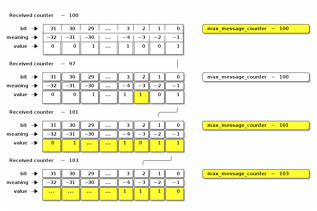
4.5.4.2. Use of Message Reception State for Encrypted Messages
The algorithm for querying and updating message reception state varies slightly depending on whether the system is tracking reception of encrypted messages or unencrypted messages.
Message Counters with maximum
For encrypted messages of Secure Unicast Session Type, any arriving message with a counter in the range [(max_message_counter + 1) to (232 - 1)] SHALL be considered new, and cause the max_message_counter value to be updated.
Message counters within the range of the bitmap SHALL be considered duplicate if the corresponding bit offset is set to true.
All other message counters SHALL be considered duplicate.
Message Counters with rollover
A message counter with rollover is a free running message counter that monotonically increases, but rolls over to zero when it exceeds the maximum value of the counter (32-bits). Group keys are secured by a shared, global message counter with rollover as described in Section 4.5.1.3, “Global Group Encrypted Message Counters”.
For encrypted messages of Group Session Type, any arriving message with a counter in the range [(max_message_counter + 1) to (max_message_counter + 231 - 1)] (modulo 232) SHALL be considered new, and cause the max_message_counter value to be updated.
Messages with counters from [(max_message_counter - 231) to (max_message_counter - MSG_COUNTER_WINDOW_SIZE - 1)] (modulo 232) SHALL be considered duplicate.
A message counter equal to max_message_counter SHALL be considered duplicate.
Message counters within the range of the bitmap SHALL be considered duplicate if the corresponding bit offset is set to true.
This scheme for encrypted messages effectively divides the message counter space in half: those counters that are forward of the max message counter, which are considered new, and those counters that are behind the max message counter, which are considered duplicates unless indicated otherwise by the values in the bitmap.
4.5.4.3. Use of Message Reception State for Unencrypted Messages
For unencrypted messages, the algorithms for tracking messages and detecting duplicates are similar to, but more permissive than for encrypted messages using Section 4.5.4.2.2, “Message Counters with rollover”. This reflects the fact that duplicate detection of unencrypted messages is not done for security reasons, but rather to catch duplicates caused by network errors (e.g. loss of an ack), which are generally more bounded in time. The more relaxed algorithm for unencrypted duplicate detection also relaxes the durability requirement on the sender’s message counter, allowing senders to store the counter in RAM.
For unencrypted messages, any message counter equal to max_message_counter or within the message counter window, where the corresponding bit is set to true SHALL be considered duplicate.
All other message counters, whether behind the window or ahead of max_message_counter, are considered new and shall update max_message_counter and shift the window accordingly.
Messages with a counter behind the window are likely caused by a node rebooting and are thus processed as rolling back the window to the current location.
Note that when max_message_counter is close to the minimum of the range, the window shall roll back to cover message counters near the maximum of the range.
4.5.4.4. Message Reception State Initialization
To initialize Message Reception State for a given Peer Node ID, initial max_message_counter, Message Type (control or data), Encryption Level (encrypted or unencrypted), and Encryption Key (for any Encryption Level except unencrypted):
-
The Message Reception State fields SHALL be set as follows:
-
The Peer Node ID SHALL reference the given Peer Node ID.
-
The Message Type SHALL be the given Message Type.
-
The Encryption Level SHALL be the given Encryption Level.
-
If the Encryption Level is NOT unencrypted, the Encryption Key SHALL reference the given key.
-
The
max_message_counterSHALL be set to the givenmax_message_counter. -
The Message Counter bitmap SHALL be set to all
1, indicating that only new messages with counter greater thanmax_message_counterSHALL be accepted.
-
4.5.5. Counter Processing of Outgoing Messages
-
Obtain the outgoing message counter of the sending Node for the given Security Flags, Session Id, and Encryption Key:
-
A message of Unsecured Session Type SHALL use the current Global Unencrypted Message Counter.
-
A message of Secure Unicast Session Type SHALL use the current Secure Session Message Counter for the session associated with the Session ID.
-
A message of Group Session Type SHALL use:
-
-
The outgoing message counter from step 1 SHALL be incremented by 1.
-
Store the incremented outgoing message counter in the OutgoingMessageCounter element associated with the Session Context for the message.
-
If the message counter wraps around from 0xFFFF_FFFF to 0x0000_0000 and the message is of Secure Unicast Session Type:
-
The Encryption Key SHALL be expired in the Session Context. The session will need to be renegotiated to resume communication after transmission of this final message.
-
-
4.5.6. Counter Processing of Incoming Messages
-
Determine the Message Reception State for the sending peer and get the current
max_message_counter.-
Given a decrypted message of Unicast Session Type:
-
Get the session-specific Message Reception State from the Secure Unicast Session Context.
-
-
Given a decrypted message of Group Session Type:
-
Extract the Source Node ID from the Message Header.
-
If there is no Source Node ID for the message, drop the message.
-
-
Get the Message Reception State for the Source Node ID of the given message:
-
If there is no Message Reception State for the groupcast message, initiate Section 4.16.4, “Unsynchronized Message Processing”.
-
-
Given an unencrypted message:
-
Get the Message Reception State associated with the Unsecured Session Context.
-
If there is no Message Reception State for the unencrypted message, create it with the information from the given message.
-
-
-
If the Message Counter is outside the valid message counter window, the message SHALL be marked as a duplicate. Note that while messages may be outside of the window for reasons other than being a duplicate, and we always mark them as such.
-
If the message is a duplicate:
-
If the message is marked as encrypted, follow Section 4.5.4.2, “Use of Message Reception State for Encrypted Messages”.
-
If the message is marked as unencrypted, follow Section 4.5.4.3, “Use of Message Reception State for Unencrypted Messages”.
-
If the message is encrypted and marked as a duplicate, i.e. Message Counter is outside the valid message counter window or marked as previously received in the Message Reception State:
-
Perform Section 4.11.5.2, “Reliable Message Processing of Incoming Messages” on the duplicate message.
-
-
Otherwise, update the Message Reception State as detailed in Section 4.5.4.1, “Message Reception State”, and accept the message for further processing.
-
4.6. Message Processing
This sub-clause describes the fundamental procedures for transmission and reception.
4.6.1. Message Transmission
To prepare a message for transmission with a given Session ID, Destination Node ID (which may be a group node id or an operational node id) and Security Flags, the following steps SHALL be performed, in order:
-
Process the message as described in Section 4.5.5, “Counter Processing of Outgoing Messages”.
-
If the message’s Session Type is a Unicast Session:
-
Set
SessionTimestampto a timestamp from a clock which would allow for the eventual determination of the last session use relative to other sessions. -
Process the message as described in Section 4.7.2, “Security Processing of Outgoing Messages”.
-
Process the message as described in Section 4.8.3, “Privacy Processing of Outgoing Messages”.
-
4.6.2. Message Reception
To process a received message, the following steps SHALL be performed in order:
-
Perform validity checks on the message; if any fail, processing of the message SHALL stop, and a 'message invalid' error SHOULD be indicated to the next higher layer:
-
The Version field SHALL be
0. -
If the message is of Secure Unicast Session Type:
-
The DSIZ field SHALL NOT indicate a Group ID is present.
-
-
If the message is of Group Session Type:
-
-
If the message is NOT of Unsecured Session Type:
-
Obtain the Privacy and Encryption Keys associated with the given Session ID:
-
If no keys are found, security processing SHALL indicate a failure to the next higher layer with a status of 'message security failed' and no further security processing SHALL be done on this message.
-
-
For each Privacy and Encryption Key, of which there may be more than one in the case of group messages:
-
If the P Flag is set, follow Section 4.8.4, “Privacy Processing of Incoming Messages” to deobfuscate the message.
-
Follow Section 4.7.3, “Security Processing of Incoming Messages” to decrypt and authenticate the message.
-
-
-
Follow Section 4.5.6, “Counter Processing of Incoming Messages” to enforce replay protection and duplicate detection.
-
If the message transport is UDP, follow Section 4.11.5.2, “Reliable Message Processing of Incoming Messages” to process message reliability.
-
If the message’s Session Type is a Unicast Session:
-
Set
SessionTimestampandActiveTimestampto a timestamp from a clock which would allow for the eventual determination of the last session use relative to other sessions.
-
-
The received message is then delivered to Section 4.9.5, “Exchange Message Processing”.
4.7. Message Security
The detailed steps involved in security processing of outgoing and incoming Matter messages are described in Section 4.7.2, “Security Processing of Outgoing Messages” and Section 4.7.3, “Security Processing of Incoming Messages” respectively. Section 4.7.1, “Data confidentiality and integrity with data origin authentication parameters” defines how the cryptographic parameters are set for securing Matter messages.
4.7.1. Data confidentiality and integrity with data origin authentication parameters
This section specifies the parameters to use the data confidentiality and integrity cryptographic primitive as defined in Section 3.6, “Data Confidentiality and Integrity”.
The parameters in this section SHALL apply for all encrypted messages, i.e. all messages except those of Unsecured Session Type.
4.7.1.1. Nonce
The nonce SHALL be formatted as specified in Table 16, “Nonce”.
| Octets: 1 | 4 | 8 |
|---|---|---|
Security Flags |
Message Counter |
Source Node ID |
The nonce used for the Authenticated Encryption with Additional Data (AEAD) algorithm (see Section 3.6, “Data Confidentiality and Integrity”) for a given message SHALL be defined as the concatenation of the Security Flags, the Message Counter, and the Source Node ID of that message. The scalar fields in the nonce, namely the Message Counter and the Source Node ID SHALL be encoded in little-endian byte order for the purposes of serialization within the nonce, that is, in the same byte ordering as the segment of the message from which its data originates.
The Source Node ID field used in the nonce SHALL be set to the Operational Node ID of the node originating security protection of the message:
-
If the message is of Secure Unicast Session Type:
-
For a CASE session, the Nonce Source Node ID SHALL be determined via the Secure Session Context associated with the Session Identifier.
-
For a PASE session, the Nonce Source Node ID SHALL be Unspecified Node ID.
-
-
If the message is of Group Session Type:
-
The S Flag of the message SHALL be
1and the Nonce Source Node ID SHALL be the Source Node ID of the message. -
If the S Flag of the message is
0the message SHALL be dropped.
-
|
Note
|
Because PASE negotiates strong one-time keys per session and the I2RKey and R2IKey are distinct for each direction of communication, the use of the Unspecified Node ID as the Nonce Source Node ID remains semantically secure.
|
4.7.2. Security Processing of Outgoing Messages
The process for encrypting Matter messages is depicted graphically in Figure 8, “Matter Message Encryption” with color code conventions described in Figure 9, “Matter Message Encryption Legend”.
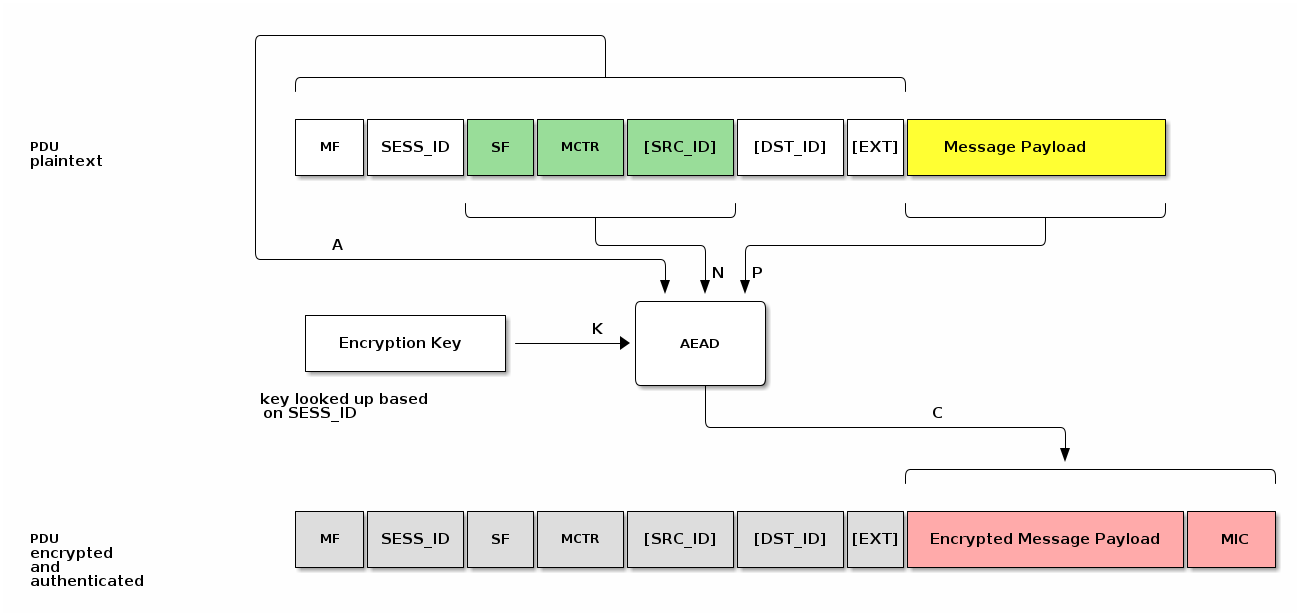
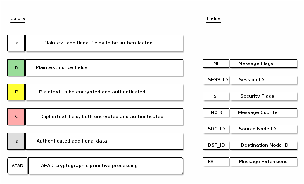
To prepare a secure message for transmission with a given Session ID, Destination Node ID (which may be a group node id or an operational node id) and Security Flags, the Node SHALL perform the following steps:
-
Obtain the Encryption Key associated with the Session ID and Destination Node ID and the Session Type associated with the Destination Node ID:
-
If no key is found for the given Session ID, security processing SHALL fail and no further security processing SHALL be done on this message.
-
-
Obtain the outgoing message counter of the sending Node as per Section 4.5.5, “Counter Processing of Outgoing Messages”.
-
Set the Security fields as follows:
-
The Session ID field SHALL be set to the value provided to step 1.
-
The Security Flags field SHALL be set to the value provided to step 1 with the following subfields updated:
-
The Session Type field SHALL be set to the value obtained from step 1.
-
-
-
Set the Message Flags, Destination Node ID, and Source Node ID fields as follows:
-
If the Session Type is a unicast session:
-
Set S Flag to 0.
-
Set DSIZ to 0.
-
Omit both Destination Node ID, and Source Node ID.
-
-
Else if the Session Type is a group session:
-
Set S Flag to 1.
-
Set DSIZ to 2.
-
Set Source Node ID field to the operational node id of the sending node.
-
Set Destination Node ID field to the 16-bit Group ID derived from the Destination Node ID.
-
-
-
Set the Message Counter field to the outgoing message counter from step 2.
-
Execute the AEAD generate and encrypt operation, as specified in Section 3.6.1, “Generate and encrypt”, with the following instantiations:
-
The bit string key K SHALL be the Encryption Key obtained from step 1;
-
The nonce N SHALL be the
CRYPTO_AEAD_NONCE_LENGTH_BYTES-octet string constructed according to Table 16, “Nonce”; -
The parameter P SHALL be the Message Payload;
-
The additional data octet string A SHALL be the Message Header contents, using little-endian byte order for all scalars, exactly as they appear in the message segments from which they originate:
Message Flags || Session ID || Security Flags || Message Counter
with the optional fields appended according to the Message Flags:
[Source Node ID] || [Destination Node ID] || [Message Extensions]
-
C = Crypto_AEAD_GenerateEncrypt(K, P, A, N)
-
-
If the AEAD operation invoked in step 6 results in an error, then security processing SHALL fail and no further security processing SHALL be done on this message.
-
Let C be the output from step 6. C contains the tag of
CRYPTO_AEAD_MIC_LENGTH_BITSbits (Message Integrity Check (MIC)) as specified by Section 3.6.1, “Generate and encrypt”. The secured outgoing message SHALL be:A || C
4.7.3. Security Processing of Incoming Messages
All incoming message processing SHALL occur in a serialized manner. If an implementation chooses to process messages in a parallel manner, it must ensure that the behavior is opaque-box identical to a serialized processing implementation.
If the transport layer receives a secured message as indicated by the Session ID, it SHALL perform the following steps:
-
Determine the Session Type, Session ID, and Message Counter from the message header of the received message.
-
Obtain the Encryption Key associated with the Session Context of the given Session ID and Session Type:
-
If no key is found for the given Session ID, security processing SHALL indicate a failure to the next higher layer with a status of 'message security failed' and no further security processing SHALL be done on this message.
-
-
Execute the AEAD decryption and verification operation as specified in Section 3.6.2, “Decrypt and verify” with the following instantiations:
-
The bit string key K SHALL be the Encryption Key obtained from step 2;
-
The nonce N SHALL be the
CRYPTO_AEAD_NONCE_LENGTH_BYTES-octet string constructed according to Table 16, “Nonce”; -
The parameter C SHALL be the encrypted and authenticated Message Payload;
-
The additional data octet string A SHALL be the authenticated Message Header:
-
{success, P} = Crypto_AEAD_DecryptVerify(K, C, A, N)
-
-
Return the result
{success, P}of the AEAD operation:-
If the
successisFALSE, security processing SHALL fail and further processing SHALL NOT be performed on this message. An appropriate error SHOULD be raised to the upper layer to indicate the error. -
Otherwise, set the octet string PlaintextMessage to the string
A || P
-
-
PlaintextMessage now represents the deciphered, authenticated, received message.
-
NOTE: The message has not yet undergone counter processing nor replay detection.
-
The PlaintextMessage SHALL be marked as successfully security processed and SHALL be released to the next processing layer.
-
4.8. Message Privacy
Privacy processing of a message describes the obfuscation and deobfuscation of the message header fields after encryption and before decryption.
The detailed steps involved in privacy processing of outgoing and incoming Matter messages are described in Section 4.8.3, “Privacy Processing of Outgoing Messages” and Section 4.8.4, “Privacy Processing of Incoming Messages” respectively. They rely on the cryptographic primitives in Section 3.7, “Message privacy”.
4.8.1. Privacy Key
The Privacy Key is a symmetric key specifically used for Privacy Processing that is derived from the EncryptionKey used for Security Processing of a given message. Given a Session ID reference to a specific Encryption Key, the Privacy Key is derived as follows:
PrivacyKey =
Crypto_KDF
(
InputKey = EncryptionKey,
Salt = [],
Info = "PrivacyKey",
Length = CRYPTO_SYMMETRIC_KEY_LENGTH_BITS
)
4.8.2. Privacy Nonce
The Privacy Nonce is a nonce specifically used for Privacy Processing that is derived from the SessionId and MIC of the message.
The Privacy Nonce SHALL be the CRYPTO_AEAD_NONCE_LENGTH_BYTES-octet string constructed as the 16-bit Session ID (in big-endian format) concatenated with the lower 11 (i.e. CRYPTO_AEAD_MIC_LENGTH_BYTES-5) bytes of the MIC:
PrivacyNonce = Session ID || MIC[5..15]
For example if Session ID is 42 (i.e. 0x002A) and the computed MIC is c5:a0:06:3a:d5:d2:51:81:91:40:0d:d6:8c:5c:16:3b:
Session ID = 00:2a MIC = c5:a0:06:3a:d5:d2:51:81:91:40:0d:d6:8c:5c:16:3b MIC[5..15] = d2:51:81:91:40:0d:d6:8c:5c:16:3b PrivacyNonce = SessionID || MIC[5..15] = 00:2a || d2:51:81:91:40:0d:d6:8c:5c:16:3b PrivacyNonce = 00:2a:d2:51:81:91:40:0d:d6:8c:5c:16:3b
4.8.3. Privacy Processing of Outgoing Messages
The process for privacy encoding Matter message headers is depicted graphically in Figure 10, “Matter Message Privacy”.
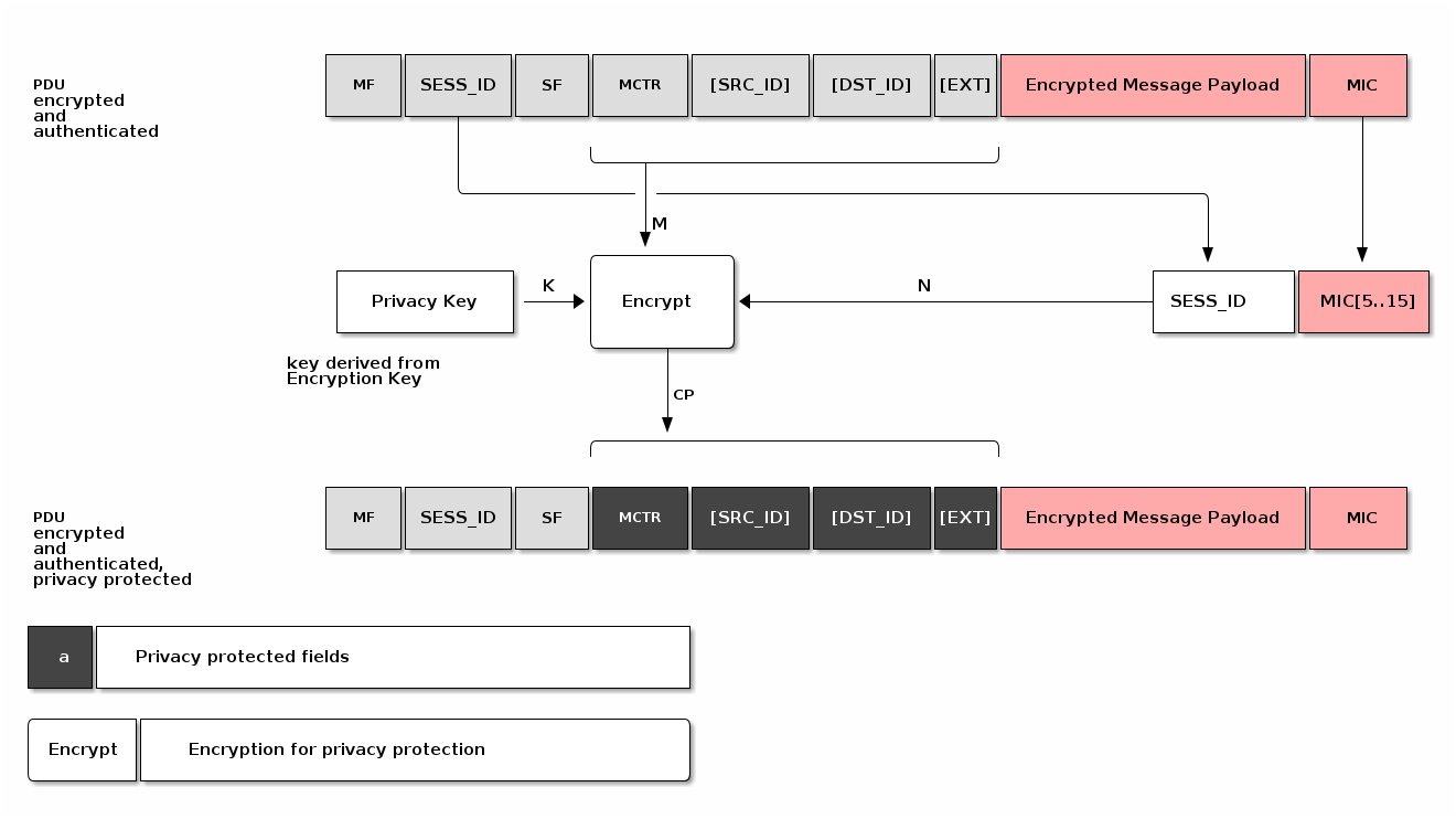
To apply privacy obfuscation to an encrypted message prepared for transmission by Section 4.6.1, “Message Transmission”, apply obfuscation steps as follows:
-
If P Flag is not set, do nothing.
-
Obtain the Privacy Key for the Encryption Key used to secure the message.
-
Execute the encryption operation as specified in Section 3.7.1, “Privacy encryption” with the following instantiations:
-
The bit string key K SHALL be the Privacy Key obtained from step 1;
-
The MIC SHALL be the last
CRYPTO_AEAD_MIC_LENGTH_BYTESbytes of theCoutcome of the message security protection as specified in Section 4.7.2, “Security Processing of Outgoing Messages” (MIC = C[(CRYPTO_AEAD_MIC_LENGTH_BYTES-1)..0]) -
The nonce N SHALL be the PrivacyNonce of the message.
-
The parameter M SHALL be the message header fields where optional fields are only present in M if they are present in the message:
M = Message Counter || [Source ID] || [Destination ID] || [Message Extensions]
-
CP = Crypto_Privacy_Encrypt(K, M, N)
-
-
Let CP be the obfuscated output from step 2. CP SHALL be used in the final private message in place of the message header fields.
4.8.4. Privacy Processing of Incoming Messages
To deobfuscate a private message received by Section 4.6.2, “Message Reception” with a given Privacy Key, perform security processing as follows:
-
If P Flag is not set, do nothing.
-
With the given Privacy Key, execute the decryption as specified in Section 3.7.2, “Privacy decryption” with the following instantiations:
-
The bit string key K SHALL be the Privacy Key obtained from step 1;
-
The MIC SHALL be the last
CRYPTO_AEAD_MIC_LENGTH_BYTESbytes of theCoutcome of the message security protection as specified in Section 4.7.3, “Security Processing of Incoming Messages” (MIC = C[(CRYPTO_AEAD_MIC_LENGTH_BYTES-1)..0]) -
The nonce N SHALL be the PrivacyNonce of the message.
-
The parameter CP SHALL be the message header fields where optional fields are only present in CP if they are present in the message:
CP = Message Counter || [Source ID] || [Destination ID] || [Message Extensions]
-
M = Crypto_Privacy_Decrypt(K, CP, N)
-
-
Let M be the deobfuscated output from step 2.
-
M SHALL be used in the final private message in place of the message header fields.
-
The first successfully validated message, M, by Section 4.7.3, “Security Processing of Incoming Messages” SHALL terminate iteration through Privacy Keys in step 2.
-
4.9. Message Exchanges
An Exchange provides a way to group related messages together, organize communication flows, and enable higher levels of the communication stack to track semantically relevant groupings of messages.
An Exchange SHALL be bound to exactly one underlying session that will transport all associated Exchange messages for the life of that Exchange. The underlying session SHALL be one of the following session types: secure unicast (as established by PASE or CASE), unsecured (as is used for the initial session establishment phase of a PASE/CASE session), secure group, or MCSP.
When used with reliability, Exchanges assume basic flow control by the upper layer. The Exchange Layer SHALL not accept a message from the upper layer when there is an outbound reliable message pending on the same Exchange.
4.9.1. Exchange Role
The first Node to send a message in an Exchange is said to be in the Initiator role, and all the other Nodes that subsequently participate in the Exchange are said to be in a Responder role. An Exchange is always between one Initiator and one or more peer Responder Nodes. An Exchange does not survive a reboot of one of the participants. Adjacent layers MAY close an Exchange at any time.
4.9.2. Exchange ID
An Exchange of messages is identified by the Exchange ID field described in Section 4.4.3.3, “Exchange ID (16 bits)”.
The Exchange ID is allocated by the Initiator.
The first message the Initiator sends in a new Exchange SHALL contain a fresh value for the Exchange ID field.
The Exchange is then identified by the tuple {Session Context, Exchange ID, Exchange Role} where Session Context is one of an Unsecured, Secured, Groupcast or MCSP session context.
All messages that are part of a given Exchange, whether they are sent by the Initiator or not, share the same Exchange ID, allowing the Initiator and Responder Nodes to match responses to requests or otherwise group messages together that are part of more complex transactions.
The first Exchange ID for a given Initiator Node SHALL be a random integer.
All subsequent Exchange IDs created by that Initiator SHALL be the last Exchange ID it created incremented by one.
An Exchange ID is an unsigned integer that rolls over to zero when its maximum value is exceeded.
4.9.3. Exchange Context
An Exchange context is the metadata tracked for an Exchange by all exchange participants. An Exchange context tracks the following data:
4.9.3.1. Protocol ID Registration
The Interaction Model layer indicates to the Exchange Layer which Protocols it will accept. Any message for a Protocol ID that is not registered with the Exchange Layer SHALL be dropped.
4.9.4. Exchange Message Dispatch
When sending a message to the Exchange Layer, the next higher layer SHALL specify whether the message is part of an existing Exchange, or the first of a new Exchange. For the case of a first message, the Initiator creates a new Exchange. The Node in the Initiator role SHALL always set the I Flag in the Exchange Flags of every message it sends in that Exchange.
Each Node in a Responder role for an Exchange SHALL use the Exchange ID received in previous messages for the Exchange. Each Node in the Responder role SHALL NOT set the I Flag in the Exchange Flags of every message it sends in that Exchange. Each Node in a Responder role SHALL NOT set the Destination Node ID field to a value that identifies any Node other than the Node in the Initiator role for the Exchange.
Processing SHALL then proceed to Section 4.11.5.1, “Reliable Message Processing of Outgoing Messages”.
4.9.5. Exchange Message Processing
After completion of Section 4.6.2, “Message Reception”, if the message matches an existing Exchange, it is dispatched to the appropriate protocol handler in the next higher layer. Messages for an existing Exchange are dispatched to the handler for that Exchange. Otherwise, the unsolicited message that created the Exchange is dispatched to the unsolicited message handler.
4.9.5.1. Exchange Message Matching
Upon receipt of a message, the Exchange Layer attempts to match the message to an existing Exchange. A given message is part of an Exchange if it satisfies all the following criteria:
-
The message was received over the session associated with the Exchange.
-
The Exchange ID of the message matches the Exchange ID of the Exchange,
-
The message has the I Flag set and the Exchange Role of the Exchange is Responder,
OR the message does not have the I Flag set and the Exchange Role of the Exchange is Initiator.
If the message does not match an existing Exchange, the message is considered an unsolicited message.
4.9.5.2. Unsolicited Message Processing
An unsolicited message is processed as follows:
-
If the unsolicited message is not marked as having a duplicate message counter, has a registered Protocol ID, and the I Flag is set:
-
Create a new exchange from the incoming message.
-
The new exchange will be used by the upper layer for generating responses and subsequent processing of the message.
-
-
Otherwise, if the message has the R Flag set:
-
Create an ephemeral exchange from the incoming message and send an immediate standalone acknowledgement.
-
The message SHALL NOT be forwarded to the upper layer, and excluding the sending of an immediate standalone acknowledgment, SHALL be ignored.
-
The ephemeral exchange created for such duplicate or unknown messages with R Flag set is automatically closed in Section 4.11.5.2.2, “Standalone acknowledgement processing”.
-
-
Otherwise, processing of the message SHALL stop.
Creating an Exchange based on an Incoming Message
The steps to create a new Exchange based on an incoming message are as follows:
-
A new Exchange and Exchange Context SHALL be created with the following settings:
-
The Exchange ID SHALL be set to the Exchange ID of the message.
-
The Exchange Role SHALL be set to the inverse of the incoming message I Flag, for example set the Exchange Role to Responder if the message is from an Initiator.
-
The Session Context SHALL be set to the Session on which the message was received.
-
A node SHOULD limit itself to a maximum of 5 concurrent exchanges over a unicast session. This is to prevent a node from exhausting the message counter window of the peer node.
4.9.5.3. Closing an Exchange
An Exchange MAY be closed by the application layer or a fatal connection error from the lower message layer. The process of closing an Exchange follows:
-
Any pending acknowledgements associated with the Exchange SHALL be flushed. If there is a pending acknowledgment in the acknowledgement table for the Exchange and it has
StandaloneAckSentset to false:-
Immediately send a standalone acknowledgement for the pending acknowledgement.
-
Remove the acknowledgement table entry for the pending acknowledgement.
-
-
Wait for all pending retransmissions associated with the Exchange to complete.
-
If the retransmission list for the Exchange is empty, remove the Exchange.
-
Otherwise, leave the Exchange open and only close it once the retransmission list is empty.
-
These steps are depicted in Figure 11, “Exchange close flow”.
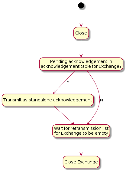
4.10. Secure Channel Protocol
This section specifies the formal protocol definition for the Secure Channel Protocol. Secure Channel Protocol defines the control plane for secure channel communication and security.
4.10.1. Secure Channel Protocol Messages
Secure Channel Protocol is composed of a collection of sub-protocols, including:
-
Message Counter Synchronization Protocol (MCSP)
-
Message Reliability Protocol (MRP)
-
Passcode Based Session Establishment (PASE)
-
Certificate Based Session Establishment (CASE)
The protocol opcodes for messages within the Secure Channel Protocol are grouped based on the underlying sub-protocol that uses the message type. Table 17, “Secure Channel Protocol Opcodes” lists the messages defined by Secure Channel Protocol.
| Protocol Opcode | Protocol Command Name | Description |
|---|---|---|
0x00 |
The Message Counter Synchronization Request message queries the current message counter from a peer to bootstrap replay protection. |
|
0x01 |
The Message Counter Synchronization Response message provides the current message counter from a peer to bootstrap replay protection. |
|
0x10 |
This message is dedicated for the purpose of sending a stand-alone acknowledgement when there is no other data message available to piggyback an acknowledgement on top of. |
|
0x20 |
The request for PBKDF parameters necessary to complete the PASE protocol. |
|
0x21 |
The PBKDF parameters sent in response to PBKDFParamRequest during the PASE protocol. |
|
0x22 |
The first PAKE message of the PASE protocol. |
|
0x23 |
The second PAKE message of the PASE protocol. |
|
0x24 |
The third PAKE message of the PASE protocol. |
|
0x30 |
The first message of the CASE protocol. |
|
0x31 |
The second message of the CASE protocol. |
|
0x32 |
The third message of the CASE protocol. |
|
0x33 |
The second resumption message of the CASE protocol. |
|
0x40 |
The Status Report message encodes the result of an operation in the Secure Channel as well as other protocols. |
|
4.10.1.1. Session Establishment - Out of Resources
After a successful session establishment using CASE or PASE, a responder may not have enough resources to save all of the session context information. To free resources, a responder SHALL evict an existing session using the following procedure:
-
Use the
SessionTimestampto determine the least-recently used session. -
Determine the session that was least-recently used then:
-
Send a status report:
StatusReport(GeneralCode: SUCCESS, ProtocolId: SECURE_CHANNEL, ProtocolCode: CLOSE_SESSION)message to the peer node -
Remove all state associated with the session (see Section 4.12.2.1, “Secure Session Context”). The Node MAY save state necessary to perform Session Resumption, see Section 4.13.2.2.1, “Session Resumption State” for more details.
-
-
Respond to the initiator with the appropriate session establishment message
4.10.1.2. Status Report
The Status Report message is sent from protocol handlers to convey the status of an operation using a common format as defined in Appendix D, Status Report Messages. The StatusReport message is a part of the Secure Channel protocol, but embeds an additional context-specific ProtocolID field in its message-specific payload. In this way, the StatusReport can convey status for any protocol handler.
4.10.1.3. Secure Channel Status Report Messages
Status Reports specific to the Secure Channel are designated by embedding the PROTOCOL_ID_SECURE_CHANNEL in the ProtocolId field of the StatusReport body.
All Secure Channel Status Report Messages SHALL use the PROTOCOL_ID_SECURE_CHANNEL protocol id. For example, a failure to find a common root of trust may be written in the specification as follows: StatusReport(GeneralCode: FAILURE, ProtocolId: SECURE_CHANNEL, ProtocolCode: NO_SHARED_TRUST_ROOTS).
There are several cases for which the secure channel layer may emit a status report:
-
To indicate successful session establishment
-
In response to errors during session establishment
-
In response to errors after session establishment
-
To indicate that a Node is terminating a session
For each of these cases, a Secure Channel Status Report message SHALL be sent with an appropriate ProtocolCode as detailed below.
The following table describes the Secure Channel Status Report Protocol Specific codes. Each entry in the list details the appropriate General Code to be utilized with the message and whether it may be sent unencrypted. Secure Channel Status Report messages which are marked as encrypted below SHALL only be sent encrypted in a session established with CASE or PASE.
| Protocol Code | Error | General Code | Encrypted | Additional Data | Description |
|---|---|---|---|---|---|
0x0000 |
SUCCESS |
N |
N |
Indication that the last session establishment message was successfully processed. |
|
0x0001 |
FAILURE |
N |
N |
Failure to find a common set of shared roots. |
|
0x0002 |
FAILURE |
N |
N |
Generic failure during session establishment. |
|
0x0003 |
SUCCESS |
Y |
N |
Indication that the sender will close the current session. See Section 4.10.1.4, “CloseSession” for more details. |
|
0x0004 |
BUSY |
N |
Y |
Indication that the sender cannot currently fulfill the request. See Section 4.10.1.5, “Busy” for more details. |
4.10.1.4. CloseSession
A node may choose to close a session for a variety of reasons including, but not limited to, the following:
-
The interaction between nodes is complete
-
The node needs to free up resources for a new session
-
Fabric configuration associated with the CASE session was removed with the RemoveFabric command invoked by an Administrator while the session was open
The CloseSession StatusReport SHALL only be sent encrypted within an exchange associated with a PASE or CASE session. The CloseSession StatusReport SHALL be sent within a new exchange and SHALL NOT set the R Flag.
If a Node has either sent or received a CloseSession StatusReport, that Node SHALL remove all state associated with the session (see Section 4.12.2.1, “Secure Session Context”). The Node MAY save state necessary to perform Session Resumption, see Section 4.13.2.2.1, “Session Resumption State” for more details.
4.10.1.5. Busy
When a receiver receives a request to start a new secure session via a Sigma1 or PBKDFParamRequest message, the receiver MAY respond with the BUSY StatusReport when it is unable to fulfill the request. The BUSY StatusReport SHALL:
-
Set the R Flag to 0
-
Set the S Flag to 0
-
Set the StatusReport
ProtocolDatato a 16-bit (two byte) little-endian value indicating the minimum time in milliseconds to wait before retrying the original request. -
Set the Exchange ID to the Exchange ID present in the Sigma1 or PBKDFParamRequest message which triggered this response.
For example, a responder wishing to indicate they are unable to fulfill the request and that the initiator should wait 500 milliseconds before trying again would send StatusReport(GeneralCode: BUSY, ProtocolId: SECURE_CHANNEL, ProtocolCode: BUSY, ProtocolData: [0xF4, 0x01]).
The BUSY StatusReport SHALL NOT be sent in response to any message except for Sigma1 or PBKDFParamRequest.
An initiator receiving a BUSY StatusReport from a responder SHALL wait for at least a period of t milliseconds before retrying the request where t is the value obtained from the Busy StatusReport ProtocolData field.
If the initiator sends a new session establishment request after receiving a BUSY StatusReport, the request SHALL contain new values for all randomized parameters.
4.10.2. Parameters and Constants
Table 19, “Glossary of constants” is a glossary of constants used in the secure channel protocol, along with a brief description and the default for each constant.
| Constant Name | Description | Value |
|---|---|---|
MSG_COUNTER_WINDOW_SIZE |
Maximum number of previously processed message counters to accept from a given Node and key. |
32 |
MSG_COUNTER_SYNC_REQ_JITTER |
Maximum amount of random delay before sending a MsgCounterSyncReq when the synchronization request is triggered by receipt of a multicast message. |
500 milliseconds |
MSG_COUNTER_SYNC_TIMEOUT |
The maximum amount of time (in milliseconds) which a Node SHALL wait for a MsgCounterSyncRsp after sending a MsgCounterSyncReq. |
400 milliseconds |
4.11. Message Reliability Protocol (MRP)
The Message Reliability Protocol (MRP) provides confirmation of delivery for messages that require reliability. The protocol is optimized for constrained devices that may not be able to receive a message at the point it is due to be delivered to them. Reliable messaging MAY be enabled on an individual message basis as required by the protocol design of the higher layer application. Reliability is achieved through time-bounded delivery confirmation, ensuring best effort delivery of critical messages over what may be an inherently lossy and unreliable communication medium.
Flow control mechanisms are not incorporated in MRP because it is intended to be used for short interactions with small numbers of messages in them.
4.11.1. Reliable Messaging Header Fields
The following fields are defined in the Exchange Flags for use exclusively by MRP:
-
Indicates a reliable message. This flag SHALL be set by the sender when a message being sent requires the receiver to send back an acknowledgment. To support unreliable messages, this flag bit MAY be clear, so that no acknowledgements are requested from the receiver.
-
Indicates the message is acting as an acknowledgement. This flag MAY be set on any message. When set, the Acknowledged Message Counter field SHALL be present and valid. This flag SHALL always be set for MRP Standalone Acknowledgement messages.
-
This field SHALL be set to the Message Counter of the message that is being acknowledged.
4.11.2. Reliable transfer
When the reliability bit is set, the reliable message is transmitted at most MRP_MAX_TRANSMISSIONS times until an acknowledgement of receipt is received from the peer or a timeout.
4.11.2.1. Retransmissions
Senders provide an automatic retransmission mechanism for reliable messages. In order for the receiver to receive a message reliably, the sender SHALL trigger the automatic retry mechanism after a period of mrpBackoffTime milliseconds without receiving an acknowledgement, where mrpBackoffTime is calculated according to the formula below. The sender SHALL retry up to a configured maximum number of times (MRP_MAX_TRANSMISSIONS - 1) before giving up and notifying the application.
Messages sent to a Node can be lost for various reasons such as lossy network or insufficient buffer space at the receiver. In the case of sleepy end devices, which wake up infrequently to receive messages destined for them, a sender must be aware of the characteristics of the recipient to ensure it does not attempt to send at a rate beyond the recipient’s capability. Therefore, the sender SHALL choose retransmission timeouts based on the sleepy characteristics of the destination Node using Section 4.3.2, “Operational Discovery”.
At each sender, a retransmission timer is started each time a reliable message is transmitted. The duration of the retransmission timer SHALL be calculated as follows:
Where:
For each unique Exchange, the sender SHALL wait for the acknowledgement message until the retransmission timer, mrpBackoffTime, expires.
A sleepy sender SHOULD increase t to also account for its own sleepy interval required to receive the acknowledgment.
The base interval, i, SHALL be set according to the active state of the peer node as stored in the Session Context of the session (either the Secure Session Context or the Unsecured Session Context depending on the Session Type).
The backoff base interval SHALL be set to a value at least 10% greater than the sleep interval of the destination:
-
If
PeerActiveModein the Session Context is true:-
i = SLEEPY_ACTIVE_INTERVALof the peer
-
-
Else the peer is in idle mode:
-
i = SLEEPY_IDLE_INTERVALof the peer
-
-
i = MRP_BACKOFF_MARGIN * i
The MRP_BACKOFF_THRESHOLD parameter creates a two-phase scheme which begins with linear backoff to improve initial latency when congestion is not the cause of packet drops, and then transitions to exponential backoff to provide convergence when the network is congested. If a positive acknowledgment is received before the retransmission timer expires, the retransmission timer is stopped. Otherwise, if the retransmission timer expires, the message is retransmitted and the timer started again.
The following table illustrates minimum, maximum, and cumulative retransmission times using default parameters.
| Metric | Transmission Time [ms] | ||||
|---|---|---|---|---|---|
Min Jitter |
330 |
330 |
528 |
845 |
1352 |
Max Jitter |
413 |
413 |
660 |
1056 |
1690 |
Min Total |
330 |
660 |
1188 |
2033 |
3385 |
Max Total |
413 |
825 |
1485 |
2541 |
4231 |
Transmission # |
0 |
1 |
2 |
3 |
4 |
The sender SHOULD initiate Section 4.3.2, “Operational Discovery” in parallel with the first retry to re-resolve the address of the destination Node if the initial transmission fails after one expected round trip. The sender SHOULD use the latest MRP parameters for the destination that result from subsequent Operational Discovery.
4.11.2.2. Acknowledgements
A receiver SHALL acknowledge a reliable message by either using a "piggybacked" acknowledgment in the next message destined to the peer, or a standalone acknowledgment, or both.
The acknowledgement message SHALL set the Acknowledged Message Counter field to the value of the Message Counter of the reliable message to be acknowledged.
Piggybacking Acknowledgments on Responses
Acknowledgements MAY be conveyed at the same time (i.e. piggybacked) as data in a response message. The receiver tries to optimize message transmission by deferring acknowledgments when a reliable message is received (see Section 4.11.5.2.2, “Standalone acknowledgement processing”) and piggybacking outstanding acknowledgments on messages that it needs to send back (see Section 4.11.5.1.1, “Piggyback acknowledgment processing” for more details).
Duplicate Message Detection
Since the reliable messaging protocol has a provision for the sender to retransmit messages, there is a significant chance that a duplicate message may arrive at the receiver. The receiver SHALL detect and mark duplicate messages that it receives using the standard authentication and replay protection mechanisms of the secure message layer (see Section 4.5.4, “Replay Prevention and Duplicate Message Detection”). The receiver SHALL send an acknowledgment message to the sender for each instance of an authenticated, reliable message, including duplicates. The reliability layer SHALL only propagate the first instance of a message to the next higher layer. Any message marked as a duplicate SHALL be dropped by the reliability layer.
4.11.3. Peer Exchange Management
The Reliable Messaging Protocol operates within the scope of an Exchange between two Nodes. MRP SHALL support one pending acknowledgement and one pending retransmission per Exchange.
MRP control parameters, detailed in Table 21, “Glossary of parameters”, are computed outside of the Exchange communication itself; instead, they are valid for the duration of a secure session. The SLEEPY_ACTIVE_INTERVAL and SLEEPY_IDLE_INTERVAL, used in computation of MRP control parameters, are determined during Operational Discovery or Section 4.3.1, “Commissionable Node Discovery”. Additionally, the initiator of a secure session MAY provide these parameters in the initial CASE Sigma1 or PASE PBKDFParamRequest messages, and the responder MAY provide its parameters in the corresponding protocol messages <ref_Sigma2, CASE Sigma2>> or PBKDFParamResponse.
4.11.5. Reliable Message Processing
4.11.5.1. Reliable Message Processing of Outgoing Messages
To prepare a given Protocol Message for transmission, the message SHALL be processed as follows:
Piggyback acknowledgment processing
-
Determine if there is a matching pending acknowledgement in the acknowledgement table for the given message by checking all of the following conditions:
-
If the Destination Node Id and Exchange Id of the given message and pending acknowledgement are the same
-
AND either
-
the Session Id and underlying Session Credentials of the given message and pending acknowledgement are the same
-
OR both the given message and pending acknowledgement are of Unsecured Session Type.
-
-
-
If there is a matching pending acknowledgement, the A Flag SHALL be set on the outbound message so it will serve as a piggybacked acknowledgement.
-
For such a piggybacked acknowledgement, the Acknowledgment Message Counter field SHALL be set to the message counter of the received message for which an acknowledgement was pending.
-
If the message being prepared is not a standalone acknowledgement, remove the matching entry from the acknowledgement table.
-
If the message being prepared is a standalone acknowledgement, set the
StandaloneAckSentfield of the matching entry in the acknowledgement table to true.
-
Message retransmission processing
-
If the outbound message is marked to be delivered reliably over a UDP transport, the R Flag SHALL be set on the given message to request an acknowledgement from the peer upon receipt.
-
Any message flagged for reliable delivery (R Flag set) SHALL be stored in the retransmission table to track the message until it has been successfully acknowledged by the peer.
-
-
Perform Section 4.6.1, “Message Transmission” processing step on the message to send the message to the peer:
-
The same Session ID, Destination Node ID, Security Flags, and transport as were used for the initial message transmission SHALL be used.
-
-
If the transport interface returns an error on the send attempt, the error is assessed to determine whether the message can be retried.
-
If the error is fatal, the application is notified and the message removed from the retransmission table.
-
If there is no error, or a non-fatal error such as no memory, the message is resent
-
Update the retransmission table to reflect the send count.
-
Start a retransmission timer to track the maximum time to wait before attempting another retransmission.
-
For each retry, the retransmission table is updated to track the number of retries until the maximum number is attempted, at which point the message is evicted from the retransmission table.
-
-
Send flow state diagram
The MRP send flow described above is depicted in the control flow diagram Figure 12, “MRP send flow”.
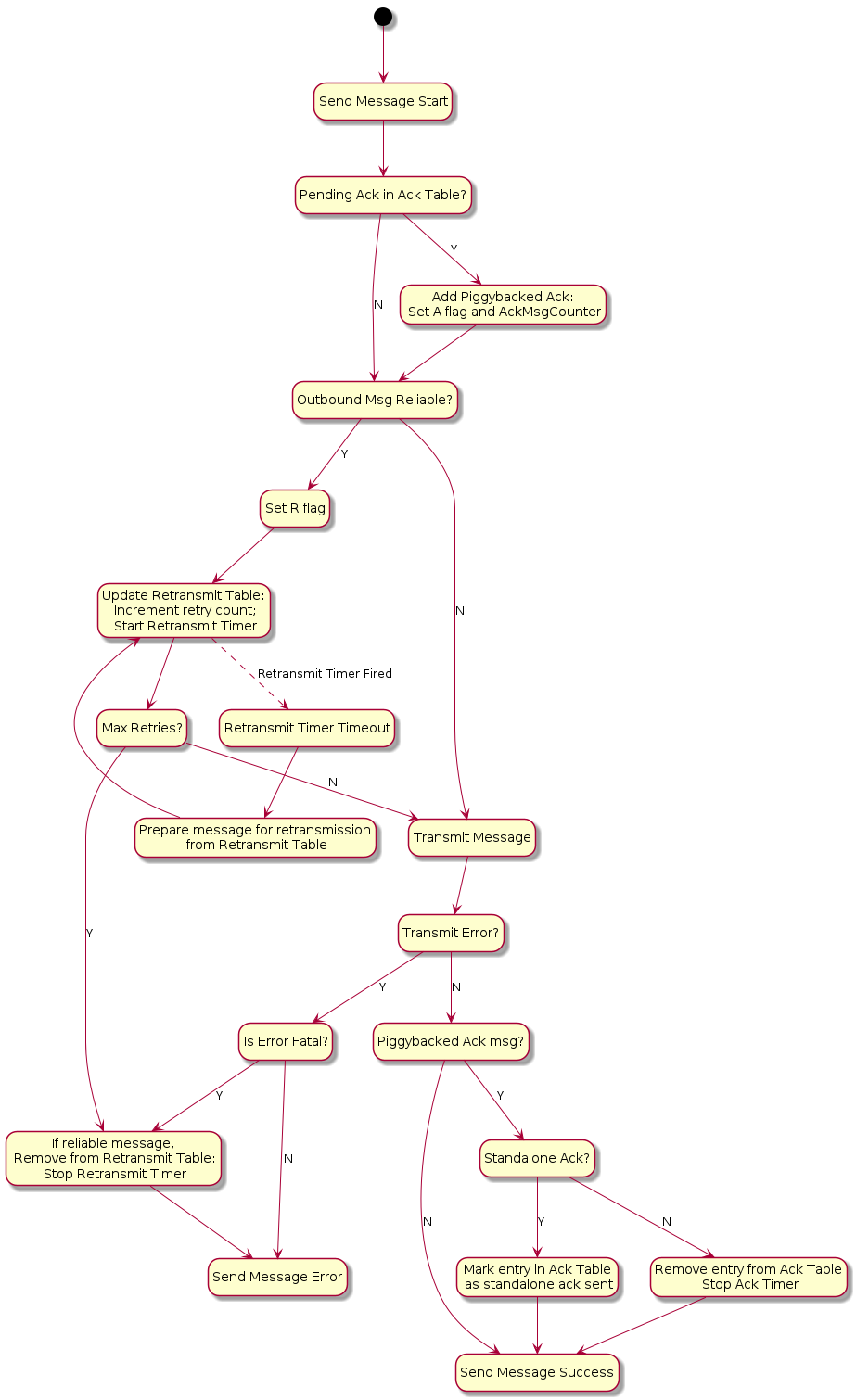
4.11.5.2. Reliable Message Processing of Incoming Messages
A message received from Section 4.6.2, “Message Reception” for reliability processing SHALL be processed as follows:
-
Verify the message has a legal combination of reliability flags:
-
If the R Flag is set:
-
If Group Session Type AND C Flag =
0, drop the message.
-
-
If the A Flag is set:
-
If Group Session Type AND C Flag =
0, drop the message.
-
-
-
Proceed to Section 4.9.5.1, “Exchange Message Matching”.
-
Proceed to Section 4.11.5.2.1, “Received acknowledgement processing”.
Received acknowledgement processing
-
If the A Flag is set:
-
Query the retransmission table for the Acknowledgement Message Counter contained in the received message.
-
If there is a match:
-
Remove the entry from the retransmission table.
-
Stop the retransmission timer for that entry.
-
-
If there is no match, it indicates that this is either a duplicate acknowledgment or the Exchange context does not exist.
-
-
-
Proceed to Section 4.11.5.2.2, “Standalone acknowledgement processing”.
Standalone acknowledgement processing
-
If the R Flag is set, the received message is requesting an acknowledgement be sent back:
-
If the message is marked as a duplicate:
-
Immediately send a standalone acknowledgment.
-
If the Exchange is marked as an ephemeral exchange the Exchange SHALL be closed.
-
Drop the message.
-
-
Otherwise, instead of sending an acknowledgement immediately upon the receipt of a reliable message from a peer, the receiver SHOULD wait for a time no longer than MRP_STANDALONE_ACK_TIMEOUT before sending a standalone acknowledgment:
-
Add the message counter of the received message to the acknowledgement table to signal that an outbound acknowledgement is pending. There can be only one outstanding acknowledgement at a time on a single Exchange. If a pending acknowledgement already exists for the Exchange, and it has
StandaloneAckSentset to false, a standalone acknowledgment SHALL be sent immediately for that pending message counter, and the acknowledgement table entry SHALL be replaced for the new message. -
Start the acknowledgement timer for the Exchange.
-
If the timer triggers before being cancelled, a standalone acknowledgment SHALL be sent to the source of the message. Sending this standalone acknowledgment SHALL NOT remove the acknowledgement table entry and SHALL set the
StandaloneAckSentfield of the entry to true.
-
-
-
-
The received message is then delivered to the next processing step of Section 4.6.2, “Message Reception”.
Receive flow state diagram
The MRP receive flow described above is depicted in Figure Figure 13, “MRP receive flow”.
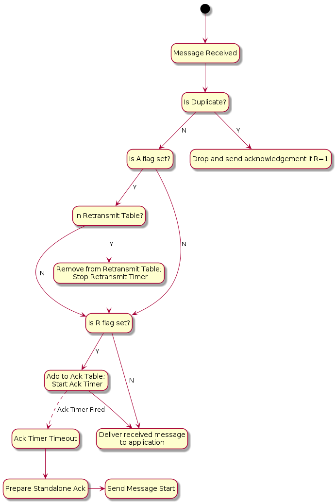
4.11.6. Reliable Message State
4.11.6.1. Retransmission Table
For retransmissions, the sender maintains a retransmission table of context records containing information on all reliable messages sent that have acknowledgments still pending. Each such reliable message context record includes the following fields:
-
Reference to Exchange Context
-
Message Counter
-
Reference to fully formed, encoded and encrypted message buffer
-
Send count
-
Retransmission timeout counter
Each time a message that requires acknowledgment is sent, a new retransmission context record is inserted into the retransmission table or an existing record is updated to increment its send count. The message is sent a configurable maximum number of times (MRP_MAX_TRANSMISSIONS) and, if still undelivered, the application is notified of the failure.
4.11.6.2. Acknowledgement Table
The receiver maintains an acknowledgement table of context records containing information on each reliable message for which an acknowledgment SHALL be sent. Each such reliable message context record includes the following fields:
-
Reference to Exchange Context
-
Message Counter
-
A boolean,
StandaloneAckSent, indicating whether a standalone acknowledgement has been sent for this message counter. Initially false.
An entry SHALL remain in the table until one of the following things happens:
-
The exchange associated with the entry is closed. See Section 4.9.5.3, “Closing an Exchange”.
-
The exchange associated with the entry has switched to track a pending acknowledgement for a new message counter value. See Section 4.11.5.2.2, “Standalone acknowledgement processing”.
-
A message that is not a standalone acknowledgement is sent which serves as an acknowledgement for the entry. See Section 4.11.5.1.1, “Piggyback acknowledgment processing”.
4.11.7. MRP Messages
4.11.7.1. MRP Standalone Acknowledgement
The MRP Standalone Acknowledgement message SHALL be formed as follows:
-
The application payload SHALL be empty.
-
The A Flag SHALL be set to
1. -
The Acknowledged Message Counter SHALL be included in the header.
-
The Protocol ID SHALL be set to
PROTOCOL_ID_SECURE_CHANNEL. -
The Protocol Opcode SHALL be set to MRP Standalone Acknowledgement.
The rules for when to send this message are detailed in Section 4.11.5.2.2, “Standalone acknowledgement processing”.
4.11.8. Parameters and Constants
Table 21, “Glossary of parameters” is a glossary of parameters used in this chapter with a brief description for each parameter. A Node SHALL use the provided default value for each parameter unless the message recipient Node advertises an alternate value for the parameter via Operational Discovery.
| Parameter Name | Description | Default Value |
|---|---|---|
MRP_MAX_TRANSMISSIONS |
The maximum number of transmission attempts for a given reliable message. The sender MAY choose this value as it sees fit. |
5 |
MRP_BACKOFF_BASE |
The base number for the exponential backoff equation. |
1.6 |
MRP_BACKOFF_JITTER |
The scaler for random jitter in the backoff equation. |
0.25 |
MRP_BACKOFF_MARGIN |
The scaler margin increase to backoff over the peer sleepy interval. |
1.1 |
MRP_BACKOFF_THRESHOLD |
The number of retransmissions before transitioning from linear to exponential backoff. |
1 |
MRP_STANDALONE_ACK_TIMEOUT |
Amount of time to wait for an opportunity to piggyback an acknowledgement on an outbound message before falling back to sending a standalone acknowledgement. |
200 milliseconds |
4.12. Unicast Communication
This section specifies the semantics of establishing a unicast session and the lifecycle of a unicast session.
Unicast sessions exist in one of two phases:
-
Session Establishment Phase: A series of well-defined unencrypted messages that aim to establish a shared key.
-
Application Data Phase: A series of ad-hoc encrypted messages exchanging interaction model protocol actions, application data, etc.
4.12.1. Session Establishment Phase
CASE SHALL be used as a session establishment mechanism for all sessions except:
-
Communication for the purpose of commissioning when NOC has not yet been installed
PASE SHALL only be used for session establishment mechanism during device commissioning. PASE SHALL NOT be used as a session establishment mechanism for any other session. BTP MAY be used as the transport for device commissioning. BTP SHALL NOT be used as a transport for operational purposes.
Unless otherwise specified, the CASE, PASE, User-Directed Commissioning protocol, and Secure Channel Status Report messages SHALL be the only allowed unencrypted messages.
This phase aims to:
-
Authenticate peers (CASE-based sessions only).
-
Derive shared secrets to encrypt subsequent session data.
-
Choose session identifiers to identify the subsequent session.
4.12.1.1. Unsecured Session Context
The following session context data SHALL be utilized to associate messages to a particular peer and recover context during unencrypted sessions:
-
Session Role: Records whether the node is the session initiator or responder. -
Ephemeral Initiator Node ID: Randomly selected for each session by the initiator from the Operational Node ID range and enclosed by initiator as Source Node ID and responder as Destination Node ID.-
Initiators SHALL select a new random ephemeral node ID for each unsecured session, and SHALL select an ID that does not conflict with any ephemeral node IDs for any other ongoing unsecured sessions opened by the initiator.
-
-
Message Reception State: Provides tracking for the Unencrypted Message Counter of the remote peer.
Matching and responder creation of Unsecured Session Contexts SHALL be as follows:
-
Given an incoming unencrypted message
-
Locate any
Unsecured Session Contextwith matchingEphemeral Initiator Node ID-
If any is located, the incoming message SHALL be assumed to be associated with this
Unsecured Session Context
-
-
Else if the message carries a Source Node ID
-
Create a new
Unsecured Session Context -
Set
Session Roletoresponder -
Record the incoming message’s Source Node ID as
Ephemeral Initiator Node ID
-
-
Else discard the message
-
Initiator creation of Unsecured Session Contexts SHALL be as follows:
-
Given the first outgoing message of an unencrypted exchange
-
Create a new
Unsecured Session Context -
Set
Session Roletoinitiator -
Randomly select a node ID from the Operational Node ID range that does not collide with any ephemeral node IDs for any other ongoing unsecured sessions opened by the initiator and record this as
Ephemeral Initiator Node ID
-
4.12.1.2. Session Establishment over IP
When establishing a session over IP, the initiator SHALL use TCP when both of the following are true:
-
The initiator supports TCP
-
The responder supports TCP as indicated by the
Tflag
If one or both nodes do not support TCP, the initiator SHALL use MRP to establish the session.
The choice of transport used during session establishment SHALL be used for the transport of messages of the established session.
4.12.1.3. Shared Secrets
Both CASE and PASE produce two shared keys: I2RKey and R2IKey. These keys will be saved to the session’s context and used to encrypt and decrypt messages during the Session Data Phase.
Nodes that support the CASE session resumption SHALL also save to the session’s context the SharedSecret computed during the CASE protocol execution.
4.12.1.4. Choosing Secure Unicast Session Identifiers
Both CASE and PASE allow each participant the ability to choose a unicast session identifier for the subsequent encrypted session. The session identifier SHALL be used to look up the relevant encryption keys and any other metadata for a particular session.
Messages using a unicast session identifier SHALL set the Session Type field to 0.
Each peer SHALL specify a Session Identifier unique in reference to their own active sessions.
There SHALL NOT be overlap between the Session ID values allocated for PASE and CASE sessions, as the Session Identifier space is shared across both session establishment methods.
For example, if the initiator has two active sessions with session identifiers 0x0001 and 0x0002, it could choose any non-zero session identifier besides 0x0001 and 0x0002.
If there are no available session identifiers (i.e. the participant has 65,535 open sessions), the Node SHALL terminate an existing session to free a session identifier.
4.12.2. Application Data Phase
When the last CASE or PASE protocol message is sent or received and successfully processed, session establishment has completed.
4.12.2.1. Secure Session Context
During the Application Data Phase, the following conceptual session context data SHALL be utilized to securely process subsequent messages:
-
Session Type: Records whether the session was established using CASE or PASE. -
Session Role: Records whether the node is the session initiator or responder. -
Local Session Identifier: Individually selected by each participant in secure unicast communication during session establishment and used as a unique identifier to recover encryption keys, authenticate incoming messages and associate them to existing sessions.-
On a given Node, this is the identifier that SHALL be used to map from an incoming message’s Session ID field to the session context data.
-
-
Peer Session Identifier: Assigned by the peer during session establishment.-
On a given Node, this is the identifier that SHALL be used in the Session ID field of every outgoing message associated with the session, so that it can be interpreted as the
Local Session Identifierby the remote peer.
-
-
I2RKey: Encrypts data in messages sent from the initiator of session establishment to the responder. -
R2IKey: Encrypts data in messages sent from the session establishment responder to the initiator. -
SharedSecret: Computed during the CASE protocol execution and re-used when CASE session resumption is implemented. -
Local Message Counter: Secure Session Message Counter for outbound messages.-
At successful session establishment, the
Local Message CounterSHALL be initialized per Section 4.5.1.1, “Message Counter Initialization”.
-
-
Message Reception State: Provides tracking for the Secure Session Message Counter of the remote peer. -
Local Fabric Index: Records the local Index for the session’s Fabric, which MAY be used to look up Fabric metadata related to the Fabric for which this session context applies.-
This field SHALL contain the "no Fabric" value of 0 when the
SessionTypeisPASEand successful invocation of the AddNOC command has not yet occurred during commissioning.
-
-
Peer Node ID: Records the authenticated node ID of the remote peer, when available.-
This field SHALL contain the "Unspecified Node ID" value of 0 when the
SessionTypeisPASE.
-
-
Resumption ID: The ID used when resuming a session between the local and remote peer. -
SessionTimestamp: A timestamp indicating the time at which the last message was sent or received. This timestamp SHALL be initialized with the time the session was created. See Section 4.10.1.1, “Session Establishment - Out of Resources” for more information. -
ActiveTimestamp: A timestamp indicating the time at which the last message was received. This timestamp SHALL be initialized with the time the session was created. -
The following sleepy parameters (see Table 5, “Glossary of parameters”):
-
SLEEPY_IDLE_INTERVAL
-
SLEEPY_ACTIVE_INTERVAL
-
PeerActiveMode: A boolean that tracks whether the peer node is in Active or Idle mode as defined in Section 2.9, “Sleepy End Device (SED)”.PeerActiveModeis set as follows:
-
Note that the Local Fabric Index and Peer Fabric Index reported in the NOC Response MAY differ in value, while still referring to the same Fabric, since for a given complete Fabric Reference, the short Fabric Index allocated during commissioning of the respective Nodes on the same Fabric MAY be different. This possible difference is due to the order in which the Fabric in question was joined in the lifecycle of the respective Nodes. See the section on AddNOC command behavior for details on Fabric Index allocation behavior over time.
There SHALL also be reservation of storage to support CASE Authenticated Tag (CAT) fields. The CAT fields are 32-bit values that MAY have been present in RDN case-authenticated-tag of the remote peer’s operational certificate, during CASE.
The CAT fields are used to cache Operational Certificate data so that it can be used by the ACL processing logic to support CASE Authenticated Tags.
Since these fields MAY be omitted from NOCs, they MAY be marked as absent in the context, such that they are not taken into account when missing. When present, they SHALL be stored. Maximum up to 3 CAT fields SHALL be supported.
Their value is unused in PASE session contexts.
4.13. Session Establishment
4.13.1. Passcode-Authenticated Session Establishment (PASE)
This section describes session establishment using a shared passcode together with an augmented Password-Authenticated Key Exchange (PAKE), in which only one party knows the passcode beforehand, to generate shared keys. This protocol is only used when commissioning a Node (i.e. the Commissionee).
4.13.1.1. Protocol Overview
The Passcode-Authenticated Session Establishment (PASE) protocol aims to establish the first session between a Commissioner and a Commissionee using a known passcode provided out-of-band. The pairing is performed using Section 3.10, “Password-Authenticated Key Exchange (PAKE)” and relies on a Password-Based Key Derivation Function (PBKDF) where the passcode is used as password.
This session establishment protocol provides a means to:
-
Communicate PBKDF parameters.
-
Derive PAKE bidirectional secrets.
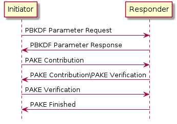
The Commissioner is the Initiator and the Commissionee is the Responder.
It is assumed that the initiator has somehow obtained the passcode and that the responder has the relevant Crypto_PAKEValues_Responder corresponding to the passcode before starting a PASE session establishment protocol.
4.13.1.2. Protocol Details
Message format
All PASE messages SHALL be structured as specified in Section 4.4, “Message Frame Format”.
All PASE messages are unsecured at the message layer:
-
The Session ID field SHALL be set to
0. -
The Session Type bits of the Security Flags SHALL be set to
0. -
The S Flag and DSIZ fields of the Message Flags SHALL be set to
0.
For each PASE message, the application payload is the TLV encoding of the message structure as defined below:
| Message Name | Payload TLV Encoding |
|---|---|
PBKDFParamRequest |
|
PBKDFParamResponse |
|
Pake1 |
|
Pake2 |
|
Pake3 |
|
PakeFinished |
N/A (encoded via StatusReport) |
The other fields of the Message format are not specific to the PASE messages.
For all TLV-encoded PASE messages, any context-specific tags not listed in the associated TLV schemas SHALL be reserved for future use, and SHALL be silently ignored if seen by a recipient which cannot understand them.
Message Exchange
The PBKDFParamRequest, PBKDFParamResponse, Pake1, Pake2, Pake3, and PakeFinished of a distinct session establishment are part of the same message exchange. The initiator and responder SHALL NOT send encrypted application data in the newly established session until PakeFinished is received by the initiator within the unencrypted session used for establishment.
Each message SHALL use PROTOCOL_ID_SECURE_CHANNEL as Protocol ID and the corresponding Protocol Opcode as defined in Table 17, “Secure Channel Protocol Opcodes”.
The flags of the Exchange Flags of the Protocol Header are defined as follows per PASE message:
| Message | I Flag |
|---|---|
PBKDFParamRequest |
1 |
PBKDFParamResponse |
0 |
Pake1 |
1 |
Pake2 |
0 |
Pake3 |
1 |
All PASE messages SHALL be sent reliably. This may be implicit (e.g. TCP) or explicit (e.g. MRP reliable messaging) in the underlying transport.
The other fields of the Protocol Header are not specific to the PASE messages.
PBKDFParamRequest
This message serves to request the PBKDF parameters, with a payload that follows this TLV schema:
pbkdfparamreq-struct => STRUCTURE [ tag-order ]
{
initiatorRandom [1] : OCTET STRING [ length 32 ],
initiatorSessionId [2] : UNSIGNED INTEGER [ range 16-bits ],
passcodeId [3] : UNSIGNED INTEGER [ length 16-bits ],
hasPBKDFParameters [4] : BOOLEAN,
initiatorSEDParams [5, optional] : sed-parameter-struct
}
-
The initiator SHALL generate a random number
InitiatorRandom = Crypto_DRBG(len = 32 * 8). -
The initiator SHALL generate a session identifier (
InitiatorSessionId) for subsequent identification of this session. TheInitiatorSessionIdfield SHALL NOT overlap with any other existing PASE or CASE session identifier in use by the responder. See Section 4.12.1.4, “Choosing Secure Unicast Session Identifiers” for more details. The initiator SHALL set theLocal Session Identifierin the Session Context to the valueInitiatorSessionId. -
The initiator SHALL choose a passcode identifier (
PasscodeId) corresponding to a particular PAKE passcode verifier installed on the responder. A value of 0 for the passcodeID SHALL correspond to the PAKE passcode verifier for the currently-open commissioning window, if any. Non-zero values are reserved for future use. For example, for initial commissioning, the verifier would be the built-in verifier matching the Onboarding Payload's passcode or, equivalently, the multi-fabric Basic Commissioning Method passcode if that method is supported. For the multi-fabric Enhanced Commissioning Method, the verifier would match the verifier provided through the OpenCommissioningWindow command. -
The initiator SHALL indicate whether the PBKDF parameters (salt and iterations) are known for the particular
passcodeId(for example from the QR code) by settingHasPBKDFParameters. IfHasPBKDFParametersis set toTrue, the responder SHALL NOT return the PBKDF parameters. IfHasPBKDFParametersis set toFalse, the responder SHALL return the PBKDF parameters. -
The initiator SHALL send a message with the appropriate Protocol Id and Protocol Opcode from Table 17, “Secure Channel Protocol Opcodes” whose payload is the TLV-encoded pbkdfparamreq-struct
PBKDFParamRequestwith an anonymous tag for the outermost struct.PBKDFParamRequest = { initiatorRandom (1) = InitiatorRandom, initiatorSessionId (2) = InitiatorSessionId, passcodeID (3) = PasscodeId, hasPBKDFParameters (4) = HasPBKDFParameters, }
PBKDFParamResponse
pbkdfparamresp-struct => STRUCTURE [ tag-order ]
{
initiatorRandom [1] : OCTET STRING [ length 32 ],
responderRandom [2] : OCTET STRING [ length 32 ],
responderSessionId [3] : UNSIGNED INTEGER [ range 16-bits ],
pbkdf_parameters [4] : Crypto_PBKDFParameterSet,
responderSEDParams [5, optional] : sed-parameter-struct
}
On receipt of PBKDFParamRequest, the responder SHALL:
-
Verify
passcodeIDis set to 0. If verification fails, the responder SHALL send a status report:StatusReport(GeneralCode: FAILURE, ProtocolId: SECURE_CHANNEL, ProtocolCode: INVALID_PARAMETER)and perform no further processing. -
Generate a random number
ResponderRandom = Crypto_DRBG(len = 32 * 8). -
Generate a session identifier (
ResponderSessionId) for subsequent identification of this session. TheResponderSessionIdfield SHALL NOT overlap with any other existing PASE or CASE session identifier in use by the responder. See Section 4.12.1.4, “Choosing Secure Unicast Session Identifiers” for more details. The responder SHALL set theLocal Session Identifierin the Session Context to the valueResponderSessionId. -
Set the
Peer Session Identifierin the Session Context to the valuePBKDFParamRequest.initiatorSessionId. -
Construct the appropriate
Crypto_PBKDFParameterSet(PBKDFParameters). IfPBKDFParamRequest.hasPBKDFParametersisTruethe responder SHALL NOT include the PBKDF parameters (i.e. salt and iteration count) in theCrypto_PBKDFParameterSet. IfMsg1.hasPBKDFParametersisFalsethe responder SHALL include the PBKDF parameters (i.e. salt and iteration count) in theCrypto_PBKDFParameterSet. -
Send a message with the appropriate Protocol Id and Protocol Opcode from Table 17, “Secure Channel Protocol Opcodes” whose payload is the TLV-encoded pbkdfparamresp-struct
PBKDFParamResponsewith an anonymous tag for the outermost struct.PBKDFParamResponse = { initiatorRandom (1) = PBKDFParamRequest.initiatorRandom, responderRandom (2) = ResponderRandom, responderSessionId (3) = ResponderSessionId, pbkdf_parameters (4) = PBKDFParameters }
Pake1
pake-1-struct => STRUCTURE [ tag-order ]
{
pA [1] : OCTET STRING [ length CRYPTO_PUBLIC_KEY_SIZE_BYTES ],
}
On receipt of PBKDFParamResponse, the initiator SHALL:
-
Set the
Peer Session Identifierin the Session Context to the valuePBKDFParamResponse.responderSessionId. -
Generate the
Crypto_PAKEValues_Initiatoraccording to thePBKDFParamResponse.pbkdf_parameters -
Using
Crypto_PAKEValues_Initiator, generatepA := Crypto_pA(Crypto_PAKEValues_Initiator) -
Send a message with the appropriate Protocol Id and Protocol Opcode from Table 17, “Secure Channel Protocol Opcodes” whose payload is the TLV-encoded pake-1-struct
Pake1with an anonymous tag for the outermost struct.Pake1 = { pA (1) = pA, }
Pake2
pake-2-struct => STRUCTURE [ tag-order ]
{
pB [1] : OCTET STRING [ length CRYPTO_PUBLIC_KEY_SIZE_BYTES ],
cB [2] : OCTET STRING [ length CRYPTO_HASH_LEN_BYTES],
}
On receipt of Pake1, the responder SHALL:
-
Compute
pB := Crypto_pB(Crypto_PAKEValues_Responder)using the passcode verifier indicated inPBKDFParamRequest -
Compute
TT := Crypto_Transcript(PBKDFParamRequest, PBKDFParamResponse, Pake1.pA, pB) -
Compute
(cA, cB, Ke) := Crypto_P2(TT, Pake1.pA, pB) -
Send a message with the appropriate Protocol Id and Protocol Opcode from Table 17, “Secure Channel Protocol Opcodes” whose payload is the TLV-encoded pake-2-struct
Pake2with an anonymous tag for the outermost struct.Pake2 = { pB (1) = pB, cB (2) = cB, }
Pake3
pake-3-struct => STRUCTURE [ tag-order ]
{
cA [1] : OCTET STRING [length CRYPTO_HASH_LEN_BYTES],
}
On receipt of Pake2, the initiator SHALL:
-
Compute
TT := Crypto_Transcript(PBKDFParamRequest, PBKDFParamResponse, Pake1.pA, Pake2.pB) -
Compute
(cA, cB, Ke) := Crypto_P2(TT, Pake1.pA, Pake2.pB) -
Verify
Pake2.cBagainstcB. If verification fails, the initiator SHALL send a status report:StatusReport(GeneralCode: FAILURE, ProtocolId: SECURE_CHANNEL, ProtocolCode: INVALID_PARAMETER)and perform no further processing. -
Send a message with the appropriate Protocol Id and Protocol Opcode from Table 17, “Secure Channel Protocol Opcodes” whose payload is the TLV-encoded pake-3-struct
Pake3with an anonymous tag for the outermost struct.Pake3 = { cA (1) = cA, } -
The initiator SHALL NOT send any encrypted application data until it receives
PakeFinishedfrom the responder.
On reception of Pake3, the responder SHALL:
-
Verify
Pake3.cAagainstcA. If verification fails, the responder SHALL send a status report:StatusReport(GeneralCode: FAILURE, ProtocolId: SECURE_CHANNEL, ProtocolCode: INVALID_PARAMETER)and perform no further processing. -
The responder SHALL set
SessionTimestampto a timestamp from a clock which would allow for the eventual determination of the last session use relative to other sessions. -
The responder SHALL encode and send PakeFinished.
PakeFinished
To indicate the successful completion of the protocol, the responder SHALL send a status report: StatusReport(GeneralCode: SUCCESS, ProtocolId: SECURE_CHANNEL, ProtocolCode: SESSION_ESTABLISHMENT_SUCCESS).
The initiator SHALL set SessionTimestamp to a timestamp from a clock which would allow for the eventual determination of the last session use relative to other sessions.
Session Encryption Keys
After verification of Pake3, each party can compute their sending and receiving session keys as described below:
byte SEKeys_Info[] = /* "SessionKeys" */
{0x53, 0x65, 0x73, 0x73, 0x69, 0x6f, 0x6e, 0x4b,
0x65, 0x79, 0x73}
I2RKey || R2IKey || AttestationChallenge =
Crypto_KDF
(
inputKey = Ke,
salt = [],
info = SEKeys_Info,
len = 3 * CRYPTO_SYMMETRIC_KEY_LENGTH_BITS
)
-
Each key is exactly
CRYPTO_SYMMETRIC_KEY_LENGTH_BITSbits. -
The initiator SHALL use
I2RKeyto encrypt and integrity protect messages and the `R2IKey' to decrypt and verify messages. -
The responder SHALL use
R2IKeyto encrypt and integrity protect messages and the `I2RKey' to decrypt and verify messages. -
The
AttestationChallengeSHALL only be used as a challenge during device attestation. See Section 6.2.3, “Device Attestation Procedure” for more details.
Upon initial installation of the new PASE Session Keys:
-
The Node SHALL initialize its Local Message Counter in the Session Context per Section 4.5.1.1, “Message Counter Initialization”.
-
The Node SHALL initialize the Message Reception State in the Session Context` and set the synchronized
max_message_counterof the peer to0.
where || indicates message concatenation and [] a zero-length array.
4.13.2. Certificate Authenticated Session Establishment (CASE)
This section describes a certificate-authenticated session establishment (CASE) protocol using Node Operational credentials. This session establishment mechanism provides an authenticated key exchange between exactly two peers while maintaining privacy of each peer. A resumption mechanism allows bootstrapping a new session from a previous one, dramatically reducing the computation required as well as reducing the number of messages exchanged.
4.13.2.1. Protocol Overview
This session establishment protocol provides a means to:
-
Mutually authenticate both peer Nodes
-
Generate cryptographic keys to secure subsequent communication within a session
-
Exchange operational parameters for the session, such as Session Identifier and MRP parameters
The cryptographic protocol mirrors the [SIGMA] protocol and uses the Identity Protection Key (IPK) to provide better identity protection. Briefly, the protocol will:
-
Exchange ephemeral elliptic curve public keys (
Sigma1.initiatorEphPubKeyandSigma2.responderEphPubKey) to generate a shared secret -
Exchange certificates to prove identities (
Sigma2.encrypted2.responderNOCandSigma3.encrypted3.initiatorNOC) -
Prove possession of the NOC private key by signing the ephemeral keys and NOC (
sigma-2-tbsdataandsigma-3-tbsdata)
The basic protocol can be achieved within 2 round trips as shown below:
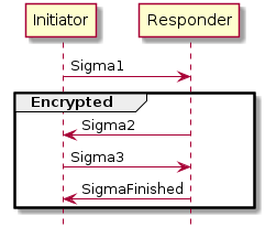
4.13.2.2. Session Resumption
The protocol also provides a means to quickly resume a session using a previously established session. Resumption does not require expensive signature creation and verification which significantly reduces the computation time. Because of this, resumption is favoured for low-powered devices when applicable. Session resumption SHOULD be used by initiators when the necessary state is known to the initiator.
The nomenclature Sigma1 with Resumption in the following subsections implies a Sigma1 message with both the optional resumptionID and initiatorResumeMIC fields populated in sigma-1-struct.
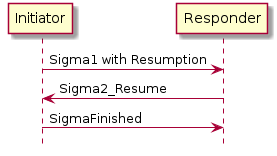
In the case where a Responder is not able to resume a session as requested by a Sigma1 with Resumption, the information included in the Sigma1 with Resumption message SHALL be processed as a Sigma1 message without any resumption fields to construct a Sigma2 message and continue the standard session establishment protocol without resumption.
To make the resumption succeed, both the Initiator and the Responder SHALL have remembered the SharedSecret they have computed during the previous execution of the CASE session establishment. It SHALL be that SharedSecret that is used to compute the resumption ID.
Session Resumption State
To perform session resumption, the following state from the previous session context must be known to the initiator and responder:
4.13.2.3. Protocol Details
Message format
All CASE messages SHALL be structured as specified in Section 4.4, “Message Frame Format”.
All CASE messages are unsecured at the message layer:
-
The Session ID field SHALL be set to
0. -
The Session Type bits of the Security Flags SHALL be set to
0. -
The S Flag and DSIZ fields of the Message Flags SHALL be set to
0.
For each CASE message, the application payload is the TLV encoding of the message structure as defined below:
| Message Name | Payload TLV Encoding |
|---|---|
Sigma1 |
|
Sigma2 |
|
Sigma3 |
|
Sigma2_Resume |
|
SigmaFinished |
N/A (encoded via StatusReport) |
The other fields of the Message format are not specific to the CASE messages.
Message Exchange
The Sigma1, Sigma2, Sigma3, and SigmaFinished of a distinct session establishment are part of the same message exchange. The Sigma1 with resumption, Sigma2_Resume and SigmaFinished of a distinct session resumption are part of the same message exchange. The Sigma1 with resumption, Sigma2, Sigma3 and SigmaFinished of a distinct session resumption that failed to perform the resumption are part of the same message exchange.
Each message SHALL use PROTOCOL_ID_SECURE_CHANNEL as Protocol ID and the corresponding Protocol Opcode as defined in Table 17, “Secure Channel Protocol Opcodes”.
The Exchange Flags of the Protocol Header are defined as follows per CASE message:
| Message | I Flag |
|---|---|
CASE Sigma1 |
1 |
CASE Sigma2 |
0 |
CASE Sigma3 |
1 |
CASE Sigma2_Resume |
0 |
For the SigmaFinished message the value of the I Flag is set depending on whether the status message is sent by the Initiator or the Responder.
All CASE messages SHALL be sent reliably. This may be implicit (e.g. TCP) or explicit (e.g. MRP reliable messaging) in the underlying transport.
The other fields of the Exchange format are not specific to the CASE messages.
Generate and Send Sigma1
The initiator encodes and sends a Sigma1 message, with a payload that follows this TLV schema:
sigma-1-struct => STRUCTURE [ tag-order ]
{
initiatorRandom [1] : OCTET STRING [ length 32 ],
initiatorSessionId [2] : UNSIGNED INTEGER [ range 16-bits ],
destinationId [3] : destination-identifier,
initiatorEphPubKey [4] : ec-pub-key,
initiatorSEDParams [5, optional] : sed-parameter-struct,
resumptionID [6, optional] : OCTET STRING [ length 16 ],
initiatorResumeMIC [7, optional] : OCTET STRING [ length CRYPTO_AEAD_MIC_LENGTH_BYTES ]
}
-
The initiator SHALL generate a random number
InitiatorRandom = Crypto_DRBG(len = 32 * 8). -
The initiator SHALL generate a session identifier (
InitiatorSessionId) for subsequent identification of this session. TheInitiatorSessionIdfield SHALL NOT overlap with any other existing PASE or CASE session identifier in use by the initiator. See Section 4.12.1.4, “Choosing Secure Unicast Session Identifiers” for more details. -
The initiator SHALL generate a destination identifier (
DestinationId) according to Destination Identifier to enable the responder to properly select a mutual Fabric and trusted root for the secure session. -
The initiator SHALL generate an ephemeral key pair
InitiatorEphKeyPair = Crypto_GenerateKeypair(). -
The initiator MAY encode any relevant MRP parameters.
-
Any context-specific tags not listed in the above TLV schemas SHALL be reserved for future use, and SHALL be silently ignored if seen by a responder which cannot understand them.
-
If the initiator is resuming a session from a previous execution of the CASE with the same peer, the initiator SHALL:
-
Note the
ResumptionIDof the previous session. -
Generate the
S1RKkey. -
Generate the
initiatorResumeMICusing theSharedSecretfrom the previous session:byte Resume1MIC_P[] = {} byte Resume1MIC_A[] = {} byte Resume1MIC_Nonce[13] = /* "NCASE_SigmaR1" */ {0x4e, 0x43, 0x41, 0x53, 0x45, 0x5f, 0x53, 0x69, 0x67, 0x6d, 0x61, 0x53, 0x31} InitiatorResume1MIC = Crypto_AEAD_GenerateEncrypt( K = S1RK, P = Resume1MIC_P, A = Resume1MIC_A, N = Resume1MIC_Nonce )
-
-
The initiator SHALL send a message with
Secure ChannelProtocol ID andSigma1Protocol Opcode from Table 17, “Secure Channel Protocol Opcodes” whose payload is the TLV-encoded Sigma1Msg1with an anonymous tag for the outermost struct.Msg1 = { initiatorRandom (1) = InitiatorRandom, initiatorSessionId (2) = InitiatorSessionId, destinationId (3) = DestinationId, initiatorEphPubKey (4) = InitiatorEphKeyPair.publicKey initiatorSEDParams (5) = sed-parameter-struct (optional), resumptionID (6) = ResumptionID (optional, only present if performing resumption), initiatorResumeMIC (7) = InitiatorResume1MIC (optional, only present if performing resumption) }
Validate Sigma1
On receipt of Msg1, the responder SHALL perform the following:
-
If
Msg1contains either aresumptionIDor aninitiatorResumeMICfield but not both, the responder SHALL send a status report:StatusReport(GeneralCode: FAILURE, ProtocolId: SECURE_CHANNEL, ProtocolCode: INVALID_PARAMETER)and perform no further processing. -
Set the
Peer Session Identifierin the Session Context to the valueMsg1.initiatorSessionId. -
If
Msg1contains both theresumptionIDandinitiatorResumeMICfields, the responder SHALL search for an existing session that has aResumption IDequal to the incomingresumptionID. If a single such session exists, the responder SHALL follow the steps in Section 4.13.2.3.10, “Validate Sigma1 with Resumption” rather than continue the steps outlined in Section 4.13.2.3.5, “Validate Sigma1 Destination ID”. -
If
Msg1does not contain aresumptionIDandinitiatorResumeMICfield, the responder SHALL continue the steps in Section 4.13.2.3.5, “Validate Sigma1 Destination ID”.
Validate Sigma1 Destination ID
-
The responder SHALL validate the incoming
destinationId:-
The responder SHALL traverse all its installed Node Operational Certificates (NOC), gathering the associated trusted roots' public keys from the associated chains and SHALL generate a
candidateDestinationIdbased on the procedure in Section 4.13.2.4.1, “Destination Identifier” for that tuple of <Root Public Key, Fabric ID, Node ID>. -
The responder SHALL verify that the incoming
destinationIdmatches one of thecandidateDestinationIdgenerated above. Upon such a match, the associated trusted root, Fabric ID, Node ID and IPK SHALL be recorded for subsequent use. -
Note that at the initiator, only the current Epoch Key for the IPK will have been used. At the receiver, several IPK Epoch Keys may be installed, requiring several
candidateDestinationIdto be computed, one per available IPK Operational Key, per NOC.
-
-
If there is no
candidateDestinationIdmatching the incomingdestinationId, the responder SHALL send a status report:StatusReport(GeneralCode: FAILURE, ProtocolId: SECURE_CHANNEL, ProtocolCode: NO_SHARED_TRUST_ROOTS)and perform no further processing. -
Otherwise, if a match was found for the
destinationId, the matched NOC, ICAC (if present), and associated trusted root SHALL be used for selection of theresponderNOCandresponderICACin the steps for Sigma2.
Generate and Send Sigma2
If validation is successful, the responder encodes and sends a Sigma2 message.
sigma-2-tbsdata => STRUCTURE [ tag-order ]
{
responderNOC [1] : OCTET STRING,
responderICAC [2, optional] : OCTET STRING,
responderEphPubKey [3] : ec-pub-key,
initiatorEphPubKey [4] : ec-pub-key,
}
sigma-2-tbedata => STRUCTURE [ tag-order ]
{
responderNOC [1] : OCTET STRING,
responderICAC [2, optional] : OCTET STRING,
signature [3] : ec-signature,
resumptionID [4] : OCTET STRING [ length 16 ],
}
sigma-2-struct => STRUCTURE [ tag-order ]
{
responderRandom [1] : OCTET STRING [ length 32 ],
responderSessionId [2] : UNSIGNED INTEGER [ range 16-bits ],
responderEphPubKey [3] : ec-pub-key,
encrypted2 [4] : OCTET STRING,
responderSEDParams [5, optional] : sed-parameter-struct
}
|
Note
|
sigma-2-tbsdata is NOT transmitted but is instead signed; the signature will be encrypted and transmitted.
|
-
The responder SHALL generate a random resumption ID
ResumptionID = Crypto_DRBG(len = 16 * 8).-
The responder SHALL set the
Resumption IDin the Session Context to the valueResumptionID.
-
-
The responder SHALL use the Node Operational Key Pair
ResponderNOKeyPair,responderNOC, andresponderICAC(if present) corresponding to the NOC obtained in Section 4.13.2.3.4, “Validate Sigma1”. -
The responder SHALL generate an ephemeral key pair
ResponderEphKeyPair = Crypto_GenerateKeypair(). -
The responder SHALL generate a shared secret:
-
The responder SHALL encode the following items as a sigma-2-tbsdata with an anonymous tag:
-
responderNOCas a matter-certificate -
responderICAC(if present) as a matter-certificate -
ResponderEphKeyPair.publicKey -
Msg1.initiatorEphPubKey -
ResumptionID
-
-
The responder SHALL generate a signature:
TBSData2Signature = Crypto_Sign( message = sigma-2-tbsdata, privateKey = ResponderNOKeyPair.privateKey ) -
The responder SHALL encode the following items as a sigma-2-tbedata, where the encoding of
responderNOCandresponderICACitems SHALL be byte-for-byte identical to the encoding insigma-2-tbsdata:-
responderNOCas a matter-certificate. This encoding SHALL be byte-for-byte identical to the encoding insigma-2-tbsdata. -
responderICAC(if present) as a matter-certificate. This encoding SHALL be byte-for-byte identical to the encoding insigma-2-tbsdata. -
TBSData2Signature
-
-
The responder SHALL generate the
S2Kkey. -
The responder SHALL generate the encrypted and integrity protected data:
byte TBEData2_A[] = {} byte TBEData2_Nonce[13] = /* "NCASE_Sigma2N" */ {0x4e, 0x43, 0x41, 0x53, 0x45, 0x5f, 0x53, 0x69, 0x67, 0x6d, 0x61, 0x32, 0x4e} TBEData2Encrypted = Crypto_AEAD_GenerateEncrypt( K = S2K, P = TBEData2, A = TBEData2_A, N = TBEData2_Nonce ) -
The responder SHALL generate a random number
Random = Crypto_DRBG(len = 32 * 8). -
The responder SHALL generate a session identifier (
ResponderSessionId) for subsequent identification of this secured session. TheResponderSessionIdfield SHALL NOT overlap with any other existing PASE or CASE session identifier in use by the responder. See Section 4.12.1.4, “Choosing Secure Unicast Session Identifiers” for more details. The responder SHALL set theLocal Session Identifierin the Session Context to the valueResponderSessionId. -
The responder SHALL use the Fabric IPK configured as described in Section 4.13.2.6.1, “Identity Protection Key (IPK)”.
-
Any context-specific tags not listed in the above TLV schemas SHALL be reserved for future use, and SHALL be silently ignored if seen by an initiator which cannot understand them.
-
The responder SHALL send a message with
Secure ChannelProtocol ID andSigma2Protocol Opcode from Table 17, “Secure Channel Protocol Opcodes” whose payload is the TLV-encoded Sigma2Msg2with an anonymous tag for the outermost struct.Msg2 = { responderRandom (1) = Random, responderSessionId (2) = ResponderSessionId, responderEphPubKey (3) = ResponderEphKeyPair.publicKey, encrypted2 (4) = TBEData2Encrypted, responderSEDParams (5) = sed-parameter-struct (optional) }
Validate Sigma2
On receipt of Msg2, the initiator SHALL perform the following:
-
The initiator SHALL generate a shared secret:
SharedSecret = Crypto_ECDH( privateKey = InitiatorEphKeyPair.privateKey, publicKey = Msg2.responderEphPubKey, ) -
The initiator SHALL generate the
S2Kkey. -
The initiator SHALL generate the decrypted data:
byte TBEData2_A[] = {} byte TBEData2_Nonce[13] = /* "NCASE_Sigma2N" */ {0x4e, 0x43, 0x41, 0x53, 0x45, 0x5f, 0x53, 0x69, 0x67, 0x6d, 0x61, 0x32, 0x4e} Success, TBEData2 = Crypto_AEAD_DecryptVerify( K = S2K, C = Msg2.encrypted2, A = TBEData2_A, N = TBEData2_Nonce ) -
If the value of
Successis FALSE, the initiator SHALL send a status report:StatusReport(GeneralCode: FAILURE, ProtocolId: SECURE_CHANNEL, ProtocolCode: INVALID_PARAMETER)and perform no further processing. -
The initiator SHALL verify that the NOC in
TBEData2.responderNOCand ICAC inTBEData2.responderICAC(if present) fulfills the following constraints:-
The Fabric ID and Node ID SHALL match the intended identity of the receiver Node, as included in the computation of the Destination Identifier when generating Sigma1.
-
If an ICAC is present, and it contains a Fabric ID in its subject, then it SHALL match the FabricID in the NOC leaf certificate.
-
The certificate chain SHALL chain back to the Trusted Root CA Certificate
TrustedRCACwhose public key was used in the computation of the Destination Identifier when generating Sigma1. -
All the elements in the certificate chain SHALL respect the Matter Certificate DN Encoding Rules, including range checks for identifiers such as Fabric ID and Node ID.
-
-
If any of the validations from the previous step fail, the initiator SHALL send a status report:
StatusReport(GeneralCode: FAILURE, ProtocolId: SECURE_CHANNEL, ProtocolCode: INVALID_PARAMETER)and perform no further processing. -
The initiator SHALL verify
TBEData2.responderNOCusing:-
Success = Crypto_VerifyChain(certificates = [TBEData2.responderNOC, TBEData2.responderICAC, TrustedRCAC]), whenTBEData2.responderICACis present, or -
Success = Crypto_VerifyChain(certificates = [TBEData2.responderNOC, TrustedRCAC]), whenTBEData2.responderICACis not present.
-
-
If the value of
SuccessisFALSE, the initiator SHALL send a status report:StatusReport(GeneralCode: FAILURE, ProtocolId: SECURE_CHANNEL, ProtocolCode: INVALID_PARAMETER)and perform no further processing. -
The initiator SHALL encode the following items as a sigma-2-tbsdata with an anonymous tag:
-
responderNOCas copied fromTBEData2 -
responderICAC(if present) as copied fromTBEData2 -
Msg2.responderEphPubKey -
InitiatorEphKeyPair.publicKey
-
-
The initiator SHALL verify
TBEData2.signature(see RFC 5280):Success = Crypto_Verify( publicKey = Public key obtained from responderNOC, message = sigma-2-tbsdata, signature = TBEData2.signature ) -
If the value of
SuccessisFALSE, the initiator SHALL send a status report:StatusReport(GeneralCode: FAILURE, ProtocolId: SECURE_CHANNEL, ProtocolCode: INVALID_PARAMETER)and perform no further processing. -
Set the
Resumption IDin the Session Context to the valueTBEData2.resumptionID. -
Set the
Peer Session Identifierin the Session Context to the valueMsg2.responderSessionId.
Generate and Send Sigma3
If validation is successful, the initiator encodes and sends a Sigma3 message.
sigma-3-tbsdata => STRUCTURE [ tag-order ]
{
initiatorNOC [1] : OCTET STRING,
initiatorICAC [2, optional] : OCTET STRING,
initiatorEphPubKey [3] : ec-pub-key,
responderEphPubKey [4] : ec-pub-key,
}
sigma-3-tbedata => STRUCTURE [ tag-order ]
{
initiatorNOC [1] : OCTET STRING,
initiatorICAC [2, optional] : OCTET STRING,
signature [3] : ec-signature,
}
sigma-3-struct => STRUCTURE [ tag-order ]
{
encrypted3 [1] : OCTET STRING,
}
|
Note
|
sigma-3-tbsdata is NOT transmitted but is instead signed; the signature will be encrypted and transmitted.
|
-
The initiator SHALL select its Node Operational Key Pair
InitiatorNOKeyPair, Node Operational CertificatesinitiatorNOCandinitiatorICAC(if present), and Trusted Root CA CertificateTrustedRCACcorresponding to the chosen Fabric as determined by the Destination Identifier from Sigma1. -
The initiator SHALL encode the following items as a sigma-3-tbsdata with an anonymous tag:
-
initiatorNOCas a matter-certificate -
initiatorICAC(if present) as a matter-certificate -
InitiatorEphKeyPair.publicKey -
Msg2.responderEphPubKey
-
-
The initiator SHALL generate a signature:
TBSData3Signature = Crypto_Sign( message = sigma-3-tbsdata, privateKey = InitiatorNOKeyPair.privateKey ) -
The initiator SHALL encode the following items as a sigma-3-tbedata:
-
initiatorNOCas a matter-certificate. This encoding SHALL be byte-for-byte identical to the encoding insigma-3-tbsdata. -
initiatorICAC(if present) as a matter-certificate. This encoding SHALL be byte-for-byte identical to the encoding insigma-3-tbsdata. -
TBSData3Signature
-
-
The initiator SHALL generate the
S3Kkey. -
The initiator SHALL generate the encrypted and integrity protected data:
byte TBEData3_A[] = {} byte TBEData3_Nonce[13] = /* "NCASE_Sigma3N" */ {0x4e, 0x43, 0x41, 0x53, 0x45, 0x5f, 0x53, 0x69, 0x67, 0x6d, 0x61, 0x33, 0x4e} TBEData3Encrypted = Crypto_AEAD_GenerateEncrypt( K = S3K, P = TBEData3, A = TBEData3_A, N = TBEData3_Nonce ) -
Any context-specific tags not listed in the above TLV schemas SHALL be reserved for future use, and SHALL be silently ignored if seen by a responder which cannot understand them.
-
The initiator SHALL send a message with
Secure ChannelProtocol ID andSigma3Protocol Opcode from Table 17, “Secure Channel Protocol Opcodes” whose payload is the TLV-encoded Sigma3Msg3 = { encrypted3 (1) = TBEData3Encrypted }with an anonymous tag for the outermost struct. -
The initiator SHALL generate the session encryption keys using the method described in Section 4.13.2.6.6, “Session Encryption Keys”.
Validate Sigma3
On receipt of Msg3, the responder SHALL perform the following:
-
The responder SHALL generate the
S3Kkey. -
The responder SHALL generate the decrypted data:
byte TBEData3_A[] = {} byte TBEData3_Nonce[13] = /* "NCASE_Sigma3N" */ {0x4e, 0x43, 0x41, 0x53, 0x45, 0x5f, 0x53, 0x69, 0x67, 0x6d, 0x61, 0x33, 0x4e} Success, TBEData3 = Crypto_AEAD_DecryptVerify( K = S3K, C = Msg3.encrypted3, A = TBEData3_A, N = TBEData3_Nonce ) -
If the value of
Successis FALSE, the responder SHALL send a status report:StatusReport(GeneralCode: FAILURE, ProtocolId: SECURE_CHANNEL, ProtocolCode: INVALID_PARAMETER)and perform no further processing. -
The responder SHALL verify that the NOC in
TBEData3.responderNOCand the ICAC inTBEData3.responderICACfulfill the following constraints:-
The Fabric ID SHALL match the Fabric ID matched during processing of the Destination Identifier after receiving Sigma1.
-
If an ICAC is present, and it contains a Fabric ID in its subject, then it SHALL match the FabricID in the NOC leaf certificate.
-
The certificate chain SHALL chain back to the Trusted Root CA Certificate
TrustedRCACwhose public key was matched during processing of the Destination Identifier after receiving Sigma1. -
All the elements in the certificate chain SHALL respect the Matter Certificate DN Encoding Rules, including range checks for identifiers such as Fabric ID and Node ID.
-
-
If any of the validations from the previous step fail, the responder SHALL send a status report:
StatusReport(GeneralCode: FAILURE, ProtocolId: SECURE_CHANNEL, ProtocolCode: INVALID_PARAMETER)and perform no further processing. -
The responder SHALL verify
TBEData3.initiatorNOCusing:-
Success = Crypto_VerifyChain(certificates = [TBEData3.initiatorNOC, TBEData3.initiatorICAC, TrustedRCAC]), whenTBEData3.initiatorICACis present, or -
Success = Crypto_VerifyChain(certificates = [TBEData3.initiatorNOC, TrustedRCAC]), whenTBEData3.initiatorICACis not present.
-
-
If the value of
SuccessisFALSE, the responder SHALL send a status report:StatusReport(GeneralCode: FAILURE, ProtocolId: SECURE_CHANNEL, ProtocolCode: INVALID_PARAMETER_)and perform no further processing. -
The responder SHALL encode the following items as a sigma-3-tbsdata with an
anonymous tag:-
initiatorNOCas copied fromTBEData3 -
initiatorICAC(if present) as copied fromTBEData3 -
Msg1.initiatorEphPubKey -
ResponderEphKeyPair.publicKey
-
-
The responder SHALL verify
TBEData3.signature(see RFC 5280):Success = Crypto_Verify( publicKey= public key obtained from initiatorNOC, message = sigma-3-tbsdata, signature = TBEData3.signature ) -
If the value of
SuccessisFALSE, the responder SHALL send a status report:StatusReport(GeneralCode: FAILURE, ProtocolId: SECURE_CHANNEL, ProtocolCode: INVALID_PARAMETER)and perform no further processing. -
The responder SHALL generate the session keys as described in Section 4.13.2.6.6, “Session Encryption Keys”.
-
The responder SHALL initialize its Local Message Counter in the Session Context per Section 4.5.1.1, “Message Counter Initialization”.
-
The responder SHALL initialize the Message Reception State in the Session Context` and set the synchronized
max_message_counterof the peer to0. -
The responder SHALL set
SessionTimestampto a timestamp from a clock which would allow for the eventual determination of the last session use relative to other sessions. -
The responder SHALL encode and send SigmaFinished.
Validate Sigma1 with Resumption
The responder SHALL continue validating the Sigma1 message Msg1 as follows:
-
Obtain the
SharedSecretfrom the Section 4.12.2.1, “Secure Session Context” of the resumed session. -
Generate the
S1RKkey. -
Verify the
Resume1MICby decrypting the following values:byte Resume1MIC_A[] = {} byte Resume1MIC_Nonce[13] = /* "NCASE_SigmaR1" */ {0x4e, 0x43, 0x41, 0x53, 0x45, 0x5f, 0x53, 0x69, 0x67, 0x6d, 0x61, 0x53, 0x31} Success, Resume1MICPayload = Crypto_AEAD_DecryptVerify( K = S1RK, C = Msg1.sigma1ResumeMIC, A = Resume1MIC_A, N = Resume1MIC_Nonce ) -
If the value of
Successis FALSE, the responder SHALL continue processingSigma1as if it didn’t include any resumption information by continuing the steps in Section 4.13.2.3.5, “Validate Sigma1 Destination ID”. -
If the value of
Successis TRUE, the responder SHALL:-
Set the
Peer Session Identifierin the in the Session Context to the valueMsg1.initiatorSessionId. -
Send a Sigma2_Resume message.
-
Generate and Send Sigma2_Resume
The responder SHALL encode and send a Sigma2_Resume message in response to a valid Sigma1 with response.
sigma-2-resume-struct => STRUCTURE [ tag-order ]
{
resumptionID [1] : OCTET STRING [ length 16 ],
sigma2ResumeMIC [2] : OCTET STRING [ length 16 ],
responderSessionID [3] : UNSIGNED INTEGER [ range 16-bits ],
responderSEDParams [4, optional] : sed-parameter-struct
}
-
The responder SHALL generate a new resumption ID
ResumptionID = Crypto_DRBG(len = 128). -
The responder SHALL generate a session identifier (
ResponderSessionId) for subsequent identification of this session. TheResponderSessionIdfield SHALL NOT overlap with any other existing PASE or CASE session identifier in use by the responder. See Section 4.12.1.4, “Choosing Secure Unicast Session Identifiers” for more details. The responder SHALL set theLocal Session Identifierin the Session Context to the valueResponderSessionId. -
The responder SHALL generate the
S2RKkey. -
The responder SHALL generate a resumption MIC:
byte Resume2MIC_P[] = {} byte Resume2MIC_A[] = {} byte Resume2MIC_Nonce[13] = /* "NCASE_SigmaR2" */ {0x4e, 0x43, 0x41, 0x53, 0x45, 0x5f, 0x53, 0x69, 0x67, 0x6d, 0x61, 0x53, 0x32} Resume2MIC = Crypto_AEAD_GenerateEncrypt( K = S2RK, P = Resume2MIC_P, A = Resume2MIC_A, N = Resume2MIC_Nonce ) -
Any context-specific tags not listed in the above TLV schemas SHALL be reserved for future use, and SHALL be silently ignored if seen by an initiator which cannot understand them.
-
The responder SHALL send a message with the
Secure ChannelProtocol ID andSigma2ResumeProtocol Opcode from Table 17, “Secure Channel Protocol Opcodes” whose payload is the TLV-encoded Sigma2_ResumeResumeMsg2with an anonymous tag for the outermost struct.ResumeMsg2 = { resumptionID (1) = ResumptionID, sigma2ResumeMIC (2) = ResumeMIC2, responderSessionID (3) = ResponderSessionId, responderSEDParams (4) = sed-parameter-struct (optional) } -
The responder SHALL generate the session keys as described in Section 4.13.2.6.7, “Resumption Session Encryption Keys”.
Validate Sigma2_Resume
On receipt of ResumeMsg2, the initiator SHALL perform the following:
-
The initiator SHALL generate the
S2RKkey. -
The initiator SHALL verify the
Resume2MICby decrypting the following values:byte Resume2MIC_A[] = {} byte Resume2MIC_Nonce[13] = /* "NCASE_SigmaR2" */ {0x4e, 0x43, 0x41, 0x53, 0x45, 0x5f, 0x53, 0x69, 0x67, 0x6d, 0x61, 0x53, 0x32} Success, Resume2MICPayload = Crypto_AEAD_DecryptVerify( K = S2RK, C = ResumeMsg2.sigma2ResumeMIC, A = Resume2MIC_A, N = Resume2MIC_Nonce ) -
If
Successis FALSE, the initiator SHALL send a status report:StatusReport(GeneralCode: FAILURE, ProtocolId: SECURE_CHANNEL, ProtocolCode: INVALID_PARAMETER_)and perform no further processing. -
The initiator SHALL set the
Resumption IDin the Session Context to the valueResume2Msg.resumptionID. -
The initiator SHALL generate the session keys as described in Section 4.13.2.6.7, “Resumption Session Encryption Keys”.
-
The initiator SHALL reset its Local Message Counter in the Session Context per Section 4.5.1.1, “Message Counter Initialization”.
-
The initiator SHALL reset the Message Reception State of the Session Context` and set the synchronized
max_message_counterof the peer to0. -
The initiator SHALL set
SessionTimestampto a timestamp from a clock which would allow for the eventual determination of the last session use relative to other sessions. -
The initiator SHALL set the
Peer Session Identifierin the in the Session Context to the valueResumeMsg2.responderSessionId. -
The initiator SHALL send Section 4.13.2.3.13, “SigmaFinished”.
SigmaFinished
To indicate the successful completion of the protocol, the Node receiving Sigma3 (if a new session is being established) or Sigma2_Resume (if a session is being resumed) SHALL send a status report: StatusReport(GeneralCode: SUCCESS, ProtocolId: SECURE_CHANNEL, ProtocolCode: SESSION_ESTABLISHMENT_SUCCESS).
On successful receipt of SigmaFinished:
-
The receiving node SHALL initialize the Local Message Counter according to Section 4.5.1.1, “Message Counter Initialization” for the newly established secure session whose success is acknowledged by this message.
-
The receiving node SHALL set
SessionTimestampto a timestamp from a clock which would allow for the eventual determination of the last session usage relative to other sessions.
If this message is received out-of-order or unexpectedly, then it SHALL be ignored.
4.13.2.4. Field Descriptions
Destination Identifier
destination-identifier => OCTET STRING [length CRYPTO_HASH_LEN_BYTES]
The Destination Identifier field enables the initiator of the Sigma1 message to unambiguously express the following, in a privacy-preserving manner:
-
Which shared Trusted Root to select
-
Which Fabric ID to use for validation of initiator and responder operational certificates
-
Which Node ID is targeted in the given Fabric
This serves several purposes:
-
It requires an initiator to have knowledge of both the IPK and one of the full identities of the responder Node before it forces the responder node to generate a costly Sigma2 message
-
Note that the replay of previously recorded initiator messages is possible, and therefore a Node MAY choose to keep memory of some prior destination identifiers which it would later reject if seen again, for additional replay protection
-
-
It ensures that there is no ambiguity on the responder as to which Fabric was selected for communication
-
It hides which Fabric was chosen by the initiator
A destination identifier is generated by:
-
Concatenating the following octet strings for subsequent usage as a
destinationMessage:-
initiatorRandom: The value ofinitiatorRandomthat will be used in the same message as the Destination Identifier -
rootPublicKey: The public key of the root of trust of the desired fabric, from theec-pub-keyfield of the Matter Certificate of that root, as an uncompressed elliptic curve point as defined in section 2.3.3 of SEC1 -
fabricId: The Fabric ID of the destination, matching thematter-fabric-idfield of the Matter Certificate of the desired destination’s NOC, and encoding the 64-bit scalar as a little-endian byte order octet string -
nodeId: The Node ID of the destination, matching thematter-node-idfield of the Matter Certificate of the desired destination’s NOC, and encoding the 64-bit scalar as a little-endian byte order octet string
-
-
Obtaining the appropriate Identity Protection Key (
IPK) Operational Group Key for the associated Fabric under Group Key Set index 0 within the Group Key Management Cluster. -
Computing an identifier
destinationIdentifierof lengthCRYPTO_HASH_LEN_BYTESusingCrypto_HMAC()with theIPKas thekeyanddestinationMessageas themessage
The above steps can be summarized as:
destinationMessage = initiatorRandom || rootPublicKey || fabricId || nodeId destinationIdentifier = Crypto_HMAC(key=IPK, message=destinationMessage)
For example, given the following:
-
Root public key for the common Fabric, in uncompressed elliptical curve point form:
RootPublicKey := // Raw uncompressed point form
04:4a:9f:42:b1:ca:48:40:d3:72:92:bb:c7:f6:a7:e1:
1e:22:20:0c:97:6f:c9:00:db:c9:8a:7a:38:3a:64:1c:
b8:25:4a:2e:56:d4:e2:95:a8:47:94:3b:4e:38:97:c4:
a7:73:e9:30:27:7b:4d:9f:be:de:8a:05:26:86:bf:ac:
fa
-
Common Fabric ID of 0x2906_C908_D115_D362 scalar (octets "62:d3:15:d1:08:c9:06:29" in little-endian)
-
Desired Destination Node ID of 0xCD55_44AA_7B13_EF14 (octets "14:ef:13:7b:aa:44:55:cd" in little-endian)
-
Identity Protection Key Epoch Key value of:
IPKEpochKey := 4a:71:cd:d7:b2:a3:ca:90:24:f9:6f:3c:96:a1:9d:ee
-
Note that this is the octet string of a group Epoch Key as would be provided in the IpkValue field of the AddNOC command in the Node Operational Credentials Cluster, or in one of the
EpochKeyfields of the KeySetWrite command in the Group Key Management Cluster. -
The derived Operational Group Key to be used for computation of a destination identifier, given the above values of root public key, Fabric ID and Identity Protection Key Epoch Key, would be:
IPK := 9b:c6:1c:d9:c6:2a:2d:f6:d6:4d:fc:aa:9d:c4:72:d4
-
-
Initiator Random value of:
7e:17:12:31:56:8d:fa:17:20:6b:3a:cc:f8:fa:ec:2f:
4d:21:b5:80:11:31:96:f4:7c:7c:4d:eb:81:0a:73:dc
Then, using the above procedure would yield the following:
-
DestinationMessage octets:
7e:17:12:31:56:8d:fa:17:20:6b:3a:cc:f8:fa:ec:2f:
4d:21:b5:80:11:31:96:f4:7c:7c:4d:eb:81:0a:73:dc:
04:4a:9f:42:b1:ca:48:40:d3:72:92:bb:c7:f6:a7:e1:
1e:22:20:0c:97:6f:c9:00:db:c9:8a:7a:38:3a:64:1c:
b8:25:4a:2e:56:d4:e2:95:a8:47:94:3b:4e:38:97:c4:
a7:73:e9:30:27:7b:4d:9f:be:de:8a:05:26:86:bf:ac:
fa:62:d3:15:d1:08:c9:06:29:14:ef:13:7b:aa:44:55:
cd
-
DestinationIdentifier octets:
dc:35:dd:5f:c9:13:4c:c5:54:45:38:c9:c3:fc:42:97:
c1:ec:33:70:c8:39:13:6a:80:e1:07:96:45:1d:4c:53
Public Key
ec-pub-key => OCTET STRING [ length CRYPTO_PUBLIC_KEY_SIZE_BYTES ]
A public key ec-pub-key is the byte string representation of an uncompressed elliptic curve point as defined in section 2.3.3 of SEC1.
4.13.2.5. Signature
An ec-signature is the encoding of the signature as defined in Section 3.5.3, “Signature and verification”.
ec-signature => OCTET STRING [ length (CRYPTO_GROUP_SIZE_BYTES * 2) ]
4.13.2.6. Cryptographic Keys
Identity Protection Key (IPK)
The Identity Protection Key (IPK) SHALL be the operational group key under GroupKeySetID of 0 for the fabric associated with the originator’s chosen destination.
The IPK SHALL be exclusively used for Certificate Authenticated Session Establishment. The IPK SHALL NOT be used for operational group communication.
For the generation of the Destination Identifier, the originator SHALL use the operational group key with the second newest EpochStartTime, if one exists, otherwise it SHALL use the single operational group key available.
The operational group key index to use to follow the "second newest EpochStartTime" rule is illustrated below:
| Number of keys in Group Key Set | Operational key index | Epoch Key |
|---|---|---|
1 |
0 |
EpochKey0 |
2 |
0 |
EpochKey0 |
3 |
1 |
EpochKey1 |
Sigma2 Key (S2K)
-
A transcript hash SHALL be generated:
TranscriptHash = Crypto_Hash(message = Msg1)
-
The Sigma2 key SHALL be generated:
byte S2K_Info[] = /* "Sigma2" */ {0x53, 0x69, 0x67, 0x6d, 0x61, 0x32} S2K = Crypto_KDF( inputKey = SharedSecret, salt = IPK || Responder Random || Responder Ephemeral Public Key || TranscriptHash, info = S2K_Info, len = CRYPTO_SYMMETRIC_KEY_LENGTH_BITS )
where || indicates message concatenation and IPK is generated according to Section 4.13.2.6.1, “Identity Protection Key (IPK)”.
Sigma3 Key (S3K)
-
A transcript hash SHALL be generated:
TranscriptHash = Crypto_Hash(message = Msg1 || Msg2)
-
The Sigma3 key SHALL be generated:
byte S3K_Info[] = /* "Sigma3" */ {0x53, 0x69, 0x67, 0x6d, 0x61, 0x33} S3K = Crypto_KDF( inputKey = SharedSecret, salt = IPK || TranscriptHash, info = S3K_Info, len = CRYPTO_SYMMETRIC_KEY_LENGTH_BITS )
where || indicates message concatenation and IPK is generated according to Section 4.13.2.6.1, “Identity Protection Key (IPK)”.
Sigma1 Resumption Key
The Sigma1 resumption key SHALL be generated:
byte S1RK_Info[] = /* "Sigma1_Resume" */
{0x53, 0x69, 0x67, 0x6d, 0x61, 0x31, 0x5f,
0x52, 0x65, 0x73, 0x75, 0x6d, 0x65}
S3K_Info
S1RK = Crypto_KDF(
inputKey = SharedSecret,
salt = Sigma1.initiatorRandom || ResumptionID,
info = S1RK_Info,
len = CRYPTO_SYMMETRIC_KEY_LENGTH_BITS
)
where || indicates message concatenation and ResumptionID is the identifier for the previous session.
Sigma2 Resumption Key
The Sigma2 resumption key SHALL be generated:
byte S2RK_Info[] = /* "Sigma2_Resume" */
{0x53, 0x69, 0x67, 0x6d, 0x61, 0x32, 0x5f,
0x52, 0x65, 0x73, 0x75, 0x6d, 0x65}
S2RK = Crypto_KDF(
inputKey = SharedSecret,
salt = Sigma1.initiatorRandom || ResumptionID,
info = S2RK_Info,
len = CRYPTO_SYMMETRIC_KEY_LENGTH_BITS
)
where || indicates message concatenation and ResumptionID is the new identifier for the this session.
Session Encryption Keys
-
A transcript hash SHALL be generated:
TranscriptHash = Crypto_Hash(message = Msg1 || Msg2 || Msg3)
-
The session encryption keys SHALL be generated:
byte SEKeys_Info[] = /* "SessionKeys" */ {0x53, 0x65, 0x73, 0x73, 0x69, 0x6f, 0x6e, 0x4b, 0x65, 0x79, 0x73} I2RKey || R2IKey || AttestationChallenge = Crypto_KDF( inputKey = SharedSecret, salt = IPK || TranscriptHash, info = SEKeys_Info, len = 3 * CRYPTO_SYMMETRIC_KEY_LENGTH_BITS ) -
Each key is exactly
CRYPTO_SYMMETRIC_KEY_LENGTH_BITSbits. -
The initiator SHALL use
I2RKeyto encrypt and integrity protect messages and the `R2IKey' to decrypt and verify messages. -
The responder SHALL use
R2IKeyto encrypt and integrity protect messages and the `I2RKey' to decrypt and verify messages. -
The
AttestationChallengeSHALL only be used as a challenge during device attestation. See Section 6.2.3, “Device Attestation Procedure” for more details.
where || indicates message concatenation.
Resumption Session Encryption Keys
-
The resumption session encryption keys SHALL be generated:
byte RSEKeys_Info[] = /* "SessionResumptionKeys" */ {0x53, 0x65, 0x73, 0x73, 0x69, 0x6f, 0x6e, 0x52, 0x65, 0x73, 0x75, 0x6d, 0x70, 0x74, 0x69, 0x6f, 0x6e, 0x4b, 0x65, 0x79, 0x73} I2RKey || R2IKey || AttestationChallenge = Crypto_KDF( inputKey = SharedSecret, salt = Sigma1.initiatorRandom || ResumptionID, info = RSEKeys_Info, len = 3 * CRYPTO_SYMMETRIC_KEY_LENGTH_BITS ) -
Each key is exactly
CRYPTO_SYMMETRIC_KEY_LENGTH_BITSbits. -
The initiator SHALL use
I2RKeyto encrypt and integrity protect messages and the `R2IKey' to decrypt and verify messages. -
The responder SHALL use
R2IKeyto encrypt and integrity protect messages and the `I2RKey' to decrypt and verify messages. -
The
AttestationChallengeSHALL only be used as a challenge during device attestation. See Section 6.2.3, “Device Attestation Procedure” for more details.
where || indicates message concatenation and ResumptionID is the new identifier for the this session.
4.13.2.7. Session Context Storage
After the session is established successfully at both peers, some fields SHALL be recorded in the secure session context for later use (see Section 4.12.2, “Application Data Phase”), in addition to the Session Encryption Keys:
-
The peer NOC's
matter-node-id(1.3.6.1.4.1.37244.1.1) from the subject field -
The Section 2.5.1, “Fabric References and Fabric Identifier” for the Fabric within which this secure session is being established
-
All peer NOC's
case-authenticated-tag(1.3.6.1.4.1.37244.1.6) from the subject field, if present
These fields MAY be recorded at any opportune point during the protocol, but SHALL only be committed to the secure session context once the session is established successfully at both peers.
4.13.2.8. Minimal Number of CASE Sessions
A node SHALL support at least 3 CASE session contexts per fabric. Device type specifications MAY require a larger minimum. Unless the device type specification says otherwise, a minimum number it defines is a per-fabric minimum.
The minimal supported capabilities, subject to the minimal constraints above, are reported in the CapabilityMinima of the Basic Information cluster.
-
Example: If a device type requires at least 4 CASE session contexts, and a node supports 7 fabrics, the node would support at least 28 CASE session contexts, and ensure that each fabric could use at least 4 of them.
4.14. Group Communication
This section specifies the semantics of sending and receiving multicast group messages and the lifecycle of such groupcast sessions. Multicast addressing is accomplished using the 16-bit Group ID field as the destination address. A multicast group is a collection of Nodes, all registered under the same multicast Group ID. A multicast message is sent to a particular destination group and is received by all members of that group.
4.14.1. Groupcast Session Context
Groupcast sessions are conceptually long-running, lasting the duration of a node’s membership in a group. Group membership is tracked in the Group Key Management Cluster. However, on ingress of each groupcast message, the following ephemeral context SHALL be constructed to inform upper layers of groupcast message provenance:
-
Fabric Index: Records the local Fabric Index for the Fabric to which an incoming message’s group is scoped. -
Group ID: Captures the Group ID to which a groupcast message was sent. -
Source Node ID: The Source Node ID enclosed by the sender of a groupcast message.-
Together, Fabric Index, Group ID and Source Node ID comprise a unique identifier that upper layers may use to understand the source and destination of groupcast messages.
-
-
Source IP Address: The unicast source IP address for the originator of the message. -
Source Port: The source port for the originator of the message.-
The source IP address and port MAY be used for unicast responses to group communication peers, as are required for the Message Counter Synchronization Protocol.
-
-
Operational Group Key: The Operational Group Key that was used to encrypt the incoming group message. -
Group Session ID: Records the Group Session ID derived from the Operational Group Key used to encrypt the message.
Once a Groupcast Session Context with trust-first policy is created to track authenticated messages from a given Source Node ID, that record SHALL NOT be deleted or recycled until the node reboots. This is to prevent replay attacks that first exhaust the memory allocated to group session counter tracking and then inject older messages as valid, and enforces that trust-first authentication works as intended within the full duration of a boot cycle. Any message from a source that cannot be tracked SHALL be dropped.
4.14.2. Sending a group message
To prepare a multicast message to a Group ID with a given GroupKeySetID and IPv6 hop count parameter, the Node SHALL:
-
Obtain, for the given GroupKeySetID, the current Operational Group Key as the Encryption Key, and the associated Group Session ID.
-
If no key is found for the given GroupKeySetID, security processing SHALL fail and no further security processing SHALL be done on this message.
-
-
Perform Section 4.6.1, “Message Transmission” processing steps on the message with the following arguments:
-
The Destination Node Id argument SHALL be the Group Node Id corresponding to the given Group ID.
-
The Session Id argument SHALL be the Group Session ID from step 1.
-
The Security Flags SHALL have only the P Flag set.
-
The transport SHALL be a site-local routable IPv6 interface.
-
Next, prepare the message as an IPv6 packet:
-
Set the private, secured message from step 2 above as the IPv6 payload.
-
Set the IPv6 hop count to the value given.
-
Set the IPv6 destination to the Section 2.5.6.2, “IPv6 Multicast Address” based on the provided destination Group ID, Fabric ID, and Section 11.2.6.2.9, “GroupKeyMulticastPolicy” of the group key.
-
Set the IPv6 source to an operational IPv6 Unicast Address of the sending Node.
-
Set the IPv6 UDP port number to the Matter IPv6 multicast port.
4.14.3. Receiving a group message
All Nodes supporting groups SHALL register to receive on the associated IPv6 multicast address, at the Matter IPv6 multicast port, for each group of which they are a member.
Upon receiving an IPv6 message addressed to one of these Multicast Addresses the Node is registered for, the Node SHALL:
-
Extract the message from the IPv6 payload.
-
Perform Section 4.6.2, “Message Reception” processing steps on the message.
4.15. Group Key Management
This section describes operational group keys, a mechanism for generating, disseminating and managing shared symmetric keys across a group of Nodes in a Fabric. Operational group keys are made available to applications for the purpose of authenticating peers, securing group communications, and encrypting data. These keys allow Nodes to:
-
Prove to each other that they are members of the associated group
-
Exchange messages confidentially, and without fear of manipulation by non-members of the group
-
Encrypt data in such a way that it can only be decrypted by other members of the group
A central feature of operational group keys is the ability to limit access to keys to a trusted set of Nodes. In particular, credentials required to generate operational group keys SHALL only be accessible to Nodes with a certain level of privilege — those deemed a member of the group. Barring software error or compromise of a privileged Node, access to shared keys SHALL be computationally infeasible for non-trusted parties.
Operational group keys are shareable across all types and combinations of Nodes as determined by the Administrator managing the group. Given all Nodes in possession of the current epoch keys for the group can communicate with other Nodes in the group, it is the responsibility of the Administrator managing the group to only compose groups of Nodes where communication is appropriate for the given application and security requirements.
4.15.1. Operational Groups
An operational group is a logical collection of Nodes that are running one or more common application clusters and share a common security domain in the form of a shared, symmetric group key. For example, a set of Nodes running a lighting application can form an operational group by sharing a common operational group key derived from the mechanisms described here. Subgroups can be formed within the operational group by defining distinct Group Identifiers for each set of Nodes, while sharing a common operational group key.
Membership in the security domain of an operational group is determined by a Node’s possession of all the epoch keys required to generate the current, valid operational group key for the group. Individual Nodes can be members of multiple operational groups simultaneously. The set of groups to which a Node belongs can change over time as dictated by application requirements and policies. Groups MAY be introduced or withdrawn over time as need arises. === Operational Group Ids Operational groups are identified uniquely within a Fabric by a Group Identifier. Administrators SHALL assign Group Ids such that no two operational groups within a Fabric have the same Group ID. It is assumed a given Administrator has sufficient access to centralized knowledge, so as to allocate unique Group Ids under a given Fabric such that there are no collisions.
Multiple operational groups MAY share the same operational group key, and thus be used to create logical subgroups over a shared security domain. Operational groups which do not share related functionality, such as a lighting group and a sprinkler group, SHOULD NOT share the same operational key. As an example policy, a lighting application could have all lighting Nodes share a single group key, while organizing lighting subgroups for various rooms or spaces within the structure by assigning a different Group ID to each such subgroup.
4.15.2. Operational Group Key Derivation
An operational group key is a symmetric key used as the Encryption Key during Message Processing for group communication. An operational group key is produced by applying a key derivation function with an epoch key and salt value as inputs as follows:
OperationalGroupKey =
Crypto_KDF
(
InputKey = Epoch Key,
Salt = CompressedFabricIdentifier,
Info = "GroupKey v1.0",
Length = CRYPTO_SYMMETRIC_KEY_LENGTH_BITS
)where [] denotes a zero-length array.
The Info portion of the key derivation is specified in Section 4.15.2.1, “Group Security Info”.
The Salt portion of the key derivation is specified in Section 4.3.2.2, “Compressed Fabric Identifier”.
For example, given:
-
An Epoch Key value of:
23:5b:f7:e6:28:23:d3:58:dc:a4:ba:50:b1:53:5f:4b -
A CompressedFabricIdentifier value of:
87:e1:b0:04:e2:35:a1:30
After the above derivation following the definition of Crypto_KDF in Section 3.8, “Key Derivation Function (KDF)”, the resulting operational group key would be: a6:f5:30:6b:af:6d:05:0a:f2:3b:a4:bd:6b:9d:d9:60.
Group membership is enforced by limiting access to the epoch keys. Only Nodes that possess the input epoch key can derive a given operational key. Lack of possession of a particular epoch key restricts access, based on the distribution policy of the epoch keys.
The following diagram shows the process by which operational keys are derived from the epoch key material:
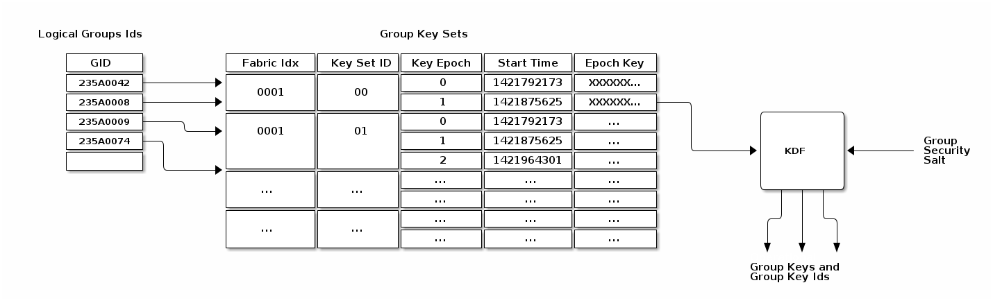
4.15.2.1. Group Security Info
A hard-coded group security info is used to diversify the set of operational group keys. This value is hard-coded into the standard’s implementation, and thus is distributed with the associated code. Should the standard’s security mechanisms need to evolve (e.g. to upgrade encryption from AES-128 to AES-256), the group security info can be changed to ensure that new keys will be derived for use in the new algorithm. The group security info SHALL be the byte stream "GroupKey v1.0", i.e. 0x47 0x72 0x6f 0x75 0x70 0x4b 0x65 0x79 0x20 0x76 0x31 0x2e 0x30.
With the exception of the group security info, all input key material SHALL be maintained on a per-Fabric basis.
4.15.2.2. Group Key Set
A group key set limits the key derivation process to Nodes within the respective operational groups. Access to a group key set is limited based on the functionality provided by a Node and/or the privilege afforded to it. For example, certain home security devices, such as a security system or door lock, may have access to a "Physical Access" group key set, while devices such as light bulbs or window coverings would not.
Operational group key lifetime is limited by assigning an expiration time to each epoch key in a given group key set. By constraining the validity of a given epoch key to an epoch, the ability for members to derive and operate with an operational group key can be constrained to particular periods of time. Epoch keys may be rotated on a periodic basis, and denying access to updated versions of these keys serves as a means to eject group members.
4.15.3. Epoch Keys
Epoch keys provide a means for limiting the lifetime of derived operational group keys. They also provide a way for an Administrator to revoke access to Nodes that have been explicitly excluded from an operational group (albeit after a period of time).
Epoch keys are generated, managed, and stored by an Administrator on a per-Fabric basis.
Each key SHALL be a random value of length CRYPTO_SYMMETRIC_KEY_LENGTH_BITS bits.
EpochKey = Crypto_DRBG(len = CRYPTO_SYMMETRIC_KEY_LENGTH_BITS)
Each epoch key has associated with it a start time that denotes the time at which the key becomes active for use by transmitting Nodes. Epoch key start times are absolute UTC time in microseconds encoded using the epoch-us representation.
4.15.3.1. Using Epoch Keys
Nodes sending group messages SHALL use operational group keys that are derived from the current epoch key (specifically, the epoch key with the latest start time that is not in the future). Nodes that cannot reliably keep track of time calculate the current epoch key as described in Section 4.15.3.4, “Epoch Key Rotation without Time Synchronization”.
Nodes receiving group messages SHALL accept the use of any key derived from one of the currently installed epoch keys. This requirement holds regardless of whether the start time for the key is in the future or the past. This means Nodes continue to accept communication secured under an epoch key until that key is withdrawn by explicitly deleting the key from a Node’s group state by the key distribution Administrator.
Note that there is no end time associated with an epoch key. An epoch key marked with the maximum start time SHALL be disabled and render the corresponding epoch key slot unused.
4.15.3.2. Managing Epoch Keys
The epoch keys are managed using the Group Key Management Cluster. For every group key set published by the key distribution Administrator, there SHALL be at least 1 and at most 3 epoch keys in rotation. Key additions or updates are done using the KeySetWrite command.
Key updates are idempotent operations to ensure the Administrator is always the source of truth. An epoch key update SHALL order the keys from oldest to newest.
Any epoch key update MAY deliver a partial key set but SHALL include EpochKey0 and MAY include EpochKey1 and EpochKey2.
Any update of the key set, including a partial update, SHALL remove all previous keys in the set, however many were defined.
An Administrator MAY completely remove a group key set from a Node using the KeySetRemove command.
4.15.3.3. Epoch Key Rotation
The key distribution Administrator generates new epoch keys on a regular basis, giving each a unique id and adding them to the list of existing epoch keys within a group. The start time for each new epoch key is scheduled to occur after a configurable key propagation interval. The propagation interval is set sufficiently large such that the Administrator can synchronize all Nodes in the operational group with the new epoch key list within that time.
The rotation rate for epoch keys is expected to be on the order of days to weeks for typical applications, but the rate is configurable as required by the key distribution Administrator. Because of the relatively long rotation interval, and the overlap of active epoch keys, local clock drift within Nodes is generally not a concern.
4.15.3.4. Epoch Key Rotation without Time Synchronization
Although epoch keys are distributed with an associated start time, it is nonetheless possible for Nodes that do not maintain a synchronized clock to participate in key rotation. Specifically, upon receiving a new epoch key list from the key distribution Administrator, such a Node can note which of the keys is the current epoch key by comparing their relative start times and using the current epoch key which has the second newest time. It can then use the current key for all locally initiated security interactions until such time as it makes contact with the distribution Administrator again.
This scheme requires the Node to receive epoch keys from the key distribution Administrator at a rate that is at least as fast as the configured key propagation interval. The Administrator SHOULD provide a sufficient set of epoch keys to Nodes that do not maintain synchronized time so that they can maintain communication with other group members while a key update is in progress. The key distribution Administrator SHOULD update all Nodes without time, such as SEDs, before the new epoch key is activated, and then let Nodes with time all roll to the new epoch key at the synchronized start time.
4.15.3.5. Epoch Key Rotation logic
The full life-cycle of Epoch Key rotation is shown in Figure 18, “Epoch Key Rotation”. For each epoch key slot, the start time of the key is shown as one of the following values:
-
New - a key with a start time in the future.
-
Current - the active key with the newest start time.
-
Previous - the active key with the second newest start time.
-
Old - an active key with the third newest start time.
The diagram shows two types of state transitions:
-
Admin - an update of an old key by the Administrator. Changes made during this state transition are indicated in green.
-
Epoch Activate - activation of an epoch key due to system time becoming greater than the start time. Changes during this state transition are indicated in yellow.
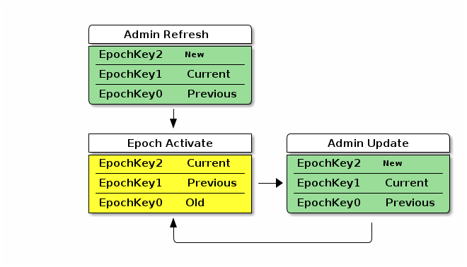
The Admin Refresh state begins when an entire group key set is freshly written to a Node during commissioning or administration, such as when a new group is added.
The Epoch Activate state is entered when time progresses to activate a fresh current epoch key, aging out the other epoch key slots.
The Admin Update state is entered when an Administrator updates an old epoch key with a new epoch key.
When in steady state, the Admin Refresh state MAY be entered in place of an Admin Update state transition to update additional keys to the required ones or to completely reset the group security.
Note that in the above diagram, only an example key distribution scheme is illustrated. It is also possible to devise key distribution algorithms that to not rely on time synchronization, or group configurations that never rotate keys in favor or configuring new groups and removing groups and group key sets with expired keys.
Group Key Set ID
The Group Key Set ID is a 16-bit field that uniquely identifies the set of epoch keys used for derivation of an operational group key. Each Group Key Set ID is scoped to a particular Fabric and assigned by an Administrator so as to be unique within a Fabric.
The Group Key Set ID of 0 SHALL be reserved for managing the Identity Protection Key (IPK) on a given Fabric.
It SHALL NOT be possible to remove the IPK Key Set if it exists.
4.15.3.6. Group Session ID
A Group Session ID is a special case of a 16-bit Session ID that is specifically used for group communication. When Session Type is 1, denoting a group session, the Session ID SHALL be a Group Session ID as defined here. The Group Session ID identifies probable operational group keys across a Fabric. The Group Session ID for a given operational group key is derived by treating the output of a Crypto_KDF against the associated Operational Group Key as a big-endian representation of a 16-bit integer, as follows:
GroupKeyHash =
Crypto_KDF
(
InputKey = OperationalGroupKey,
Salt = [],
Info = "GroupKeyHash",
Length = 16 // Bits
)
// GroupKeyHash is an array of 2 bytes (16 bits) per Crypto_KDF
// GroupSessionId is computed by considering the GroupKeyHash as a Big-Endian
// value. GroupSessionId is a scalar. Its use in fields within messages may cause a
// re-serialization into a different byte order than the one used for initial generation.
GroupSessionId = (GroupKeyHash[0] << 8) | (GroupKeyHash[1] << 0)where [] denotes a zero-length array.
For example, given:
-
An Operational Group Key value of:
a6:f5:30:6b:af:6d:05:0a:f2:3b:a4:bd:6b:9d:d9:60
After the above derivation following the definition of Crypto_KDF in Section 3.8, “Key Derivation Function (KDF)”, the resulting Group Session ID data would be:
-
Raw output of GroupKeyHash:
b9:f7 -
Group Session ID scalar value to be used for further processing: 0xB9F7 (47607 decimal)
The Group Session ID MAY help receiving nodes efficiently locate the Operational Group Key used to encrypt an incoming groupcast message. It SHALL NOT be used as the sole means to locate the associated Operational Group Key, since it MAY collide within the fabric. Instead, the Group Session ID provides receiving nodes a means to identify Operational Group Key candidates without the need to first attempt to decrypt groupcast messages using all available keys.
On receipt of a message of Group Session Type, all valid, installed, operational group key candidates referenced by the given Group Session ID SHALL be attempted until authentication is passed or there are no more operational group keys to try. This is done because the same Group Session ID might arise from different keys. The chance of a Group Session ID collision is 2-16 but the chance of both a Group Session ID collision and the message MIC matching two different operational group keys is 2-80.
Group Session Ids are sized to fit within the context of the Session Identifier field of a message. When used in this context, the Group Session ID value allows a receiving Node to identify the appropriate message encryption key to use from the set of active operational keys it has currently installed.
4.15.4. Distribution of Key Material
The operational group keys mechanism relies on a key distribution Administrator to reliably distribute select epoch key material to appropriate participants. It is assumed the key distribution Administrator is in possession of all epoch keys, has knowledge of the set of group security domain members which require access to those keys, and is responsible for pushing updates of these credentials to all authorized Nodes in those groups it manages.
Key material is distributed to key holders using the Group Key Management Cluster. In general, the key material of a Node is exposed via Attributes with ACL entries that only allow access by the key distribution Administrator. The information exposed in the Section 11.2, “Group Key Management Cluster” includes the group epoch keys and associated group session identifiers.
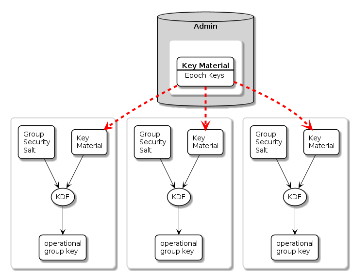
4.15.4.1. Installing a Group onto a Newly Commissioned Node
This section provides an example of the operations required to install a group onto a newly commissioned node.
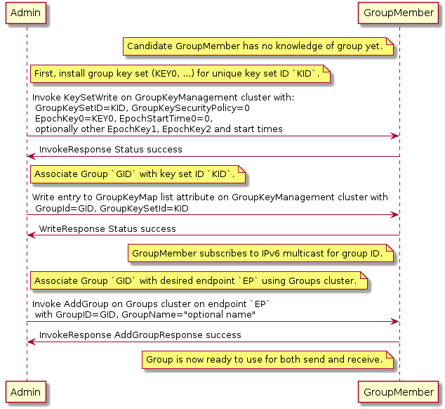
Sequence:
-
Admin:
-
Generate fabric-unique group ID
GIDand random keykey0for group key set IDK. -
Write the group key set
Kto the remote node, GroupMember, usingKeySetWritecommand. -
Associate group ID
GIDwith key setKby writing an entry to the GroupKeyMap list attribute.
-
-
GroupMember:
-
Node subscribes to the IPv6 multicast address generated from the fabric ID and group ID.
-
-
Admin:
-
Associate endpoint with group ID
GIDby sending theGroupscluster’sAddGroupcommand to endpoint.
-
4.16. Message Counter Synchronization Protocol (MCSP)
This section describes the protocol used to securely synchronize the message counter used by a sender of messages encrypted with a symmetric group key.
Message counter synchronization is an essential part of enabling secure messaging between members of an operational group. Specifically, it protects against replay attacks, where an attacker replays older messages, which may result in unexpected behaviour if accepted and processed by the receiver.
The recipient of a message encrypted with a group key can trust and process that message only if it has kept the last message counter received from a given sender using that key.
Underlying MCSP is a simple request / response protocol. When a multicast message with unknown counter is received, synchronization via MCSP begins by sending a synchronization request via unicast UDP to the multicast message originator’s unicast IPv6 address. That originator then sends a synchronization response to the unsynchronized node via unicast UDP. After cryptographic verification, the formerly unsynchronized node is now synchronized with the originator’s message counter and can trust the original and subsequent messages from the originator node.
4.16.1. Message Counter Synchronization Methods
There are two methods for synchronizing the message counter of a peer node, which are configurable per-group-key based on the GroupKeySecurityPolicy field of a given group key set (see GroupKeySetStruct).
4.16.1.1. Trust-first policy
The first authenticated message counter from an unsynchronized peer is trusted, and its message counter is used to configure message-counter-based replay protection on future messages from that node. All control messages (any message with C Flag set) use the control message counter and SHALL use Trust-first for synchronization. Note that MCSP is not used for Trust-first synchronization.
This policy provides lower latency for less security-sensitive applications such as lighting.
|
Warning
|
Trust-first synchronization is susceptible to accepting a replayed message after a Node has been rebooted. |
4.16.1.2. Cache-and-sync policy
The message that triggers message counter synchronization is stored, a message counter synchronization exchange is initiated, and only when the synchronization is completed is the original message processed. Cache-and-sync provides replay protection even in the case where a Node has been rebooted, at the expense of higher latency.
Support for the cache-and-sync policy and MCSP is optional. A node indicates its ability to support this feature via the Group Key Management cluster FeatureMap.
4.16.2. Group Peer State
The Group Peer State Table stores information about every peer with which the node had a group message exchange. For every peer node id the following information is available in the table:
-
Peer’s Encrypted Group Data Message Counter Status:
-
Synchronized Data Message Counter - the largest encrypted data message counter received from the peer, if available.
-
Flag to indicate whether this counter value is valid and synchronized.
-
The message reception state bitmap tracking the recent window of data message counters received from the peer.
-
-
Peer’s Encrypted Group Control Message Counter Status:
-
Synchronized Control Message Counter - the largest encrypted control message counter received from the peer, if available.
-
Flag to indicate whether this counter value is valid and synchronized.
-
The message reception state bitmap tracking the recent window of control message counters received from the peer.
-
There are three scenarios where the receiver of an encrypted message does not know the sender’s last message counter:
-
The encrypted message is the first received from a peer.
-
The device rebooted without persisting the Group Peer State Table content. Note: it is not required to persist the Peer State Table.
-
The entry for the Peer in the Group Peer State Table was expunged due to the table being full.
The next sections describe the functional protocol used to request message counter synchronization with a peer and form responses to such message counter synchronization requests.
4.16.3. MCSP Messages
4.16.3.1. MsgCounterSyncReq - Message Counter Synchronization Request
The Message Counter Synchronization Request (MsgCounterSyncReq) message is sent when a message was received from a peer whose current message counter is unknown.
A MsgCounterSyncReq message SHALL set the C Flag in the message header. The control message counter SHALL be used for message protection.
A MsgCounterSyncReq message SHALL be secured with the group key for which counter synchronization is requested and SHALL set the Session Type to 1, indicating a group session as per the rules outline in Section 4.16.5, “Message Counter Synchronization Exchange”.
The payload of the MsgCounterSyncReq message takes the format defined in Table 24, “Message Counter Sync Request”:
| Field Size | Message Field | Description |
|---|---|---|
8 bytes |
Challenge |
The Challenge is a 64-bit random number generated using the DRBG by the initiator of a MsgCounterSyncReq to uniquely identify the synchronization request cryptographically. |
4.16.3.2. MsgCounterSyncRsp - Message Counter Synchronization Response
The Message Counter Synchronization Response (MsgCounterSyncRsp) message is sent in response to a MsgCounterSyncReq.
A MsgCounterSyncRsp message SHALL set the C Flag in the message header. The control message counter SHALL be used for message protection.
The MsgCounterSyncRsp message has the format defined in Table 25, “Message Counter Sync Response”:
| Field Size | Message Field | Description |
|---|---|---|
4 bytes |
Synchronized Counter |
The current data message counter for the node sending the MsgCounterSyncRsp message. |
8 bytes |
Response |
The Response SHALL be the same as the 64-bit value sent in the Challenge field of the corresponding MsgCounterSyncReq. |
4.16.4. Unsynchronized Message Processing
An unsynchronized message is one that is cryptographically verified from a node whose message counter is unknown. Upon receipt of an unsynchronized message process the message as follows:
-
The message SHALL be of Group Session Type, otherwise discard the message.
-
If C Flag is set to
1:-
Create a Message Reception State and set its
max_message_counterto the message counter of the given message, i.e. trust-first. -
Accept the message for further processing.
-
-
If C Flag is set to
0:-
Determine the Section 11.2.6.2.2, “GroupKeySecurityPolicy” (as set by the Section 11.2, “Group Key Management Cluster”) of the operational group key used to authenticate the message.
-
If the key has a trust-first security policy, the receiver SHALL:
-
Set the peer’s group key data message counter to Message Counter of the message.
-
Clear the Message Reception State bitmap for the group session from the peer.
-
Mark the peer 's group key data message counter as synchronized.
-
-
Process the message.
-
-
If the key has a cache-and-sync security policy, the receiver SHALL:
-
If MCSP is not in progress for the given peer Node ID and group key:
-
Store the message for later processing.
-
Proceed to Section 4.16.5, “Message Counter Synchronization Exchange”.
-
-
Otherwise, do not process the message.
-
An implementation MAY queue the message for later processing after MCSP completes if resources allow.
-
-
-
For each peer Node ID and group key pair there SHALL be at most one synchronization exchange outstanding at a time.
4.16.5. Message Counter Synchronization Exchange
A message synchronization exchange starts by sending the MsgCounterSyncReq message to the peer Node that sent the message with unknown message counter.
When a synchronization request is triggered by an incoming multicast message, the Node SHALL first wait for a uniformly random amount of time between 0 and MSG_COUNTER_SYNC_REQ_JITTER.
The sender of the MsgCounterSyncReq message SHALL:
-
Set the Message Header fields as follows:
-
The S Flag SHALL be set to
1. -
The DSIZ field SHALL be set to
1. -
The P Flag SHALL be set to
1. -
The C Flag SHALL be set to
1. -
The Session Type field SHALL be set to
1. -
The Session ID field SHALL be set to the Group Session Id for the operational group key being synchronized.
-
The Source Node ID field SHALL be set to the Node ID of the sender Node.
-
The Destination Node ID field SHALL be set to the Source Node ID of the message that triggered the synchronization attempt.
-
-
Create a new synchronization Exchange.
-
The Exchange ID of the message SHALL be set to match the new Exchange.
-
The I Flag SHALL be set to
1. -
The A Flag SHALL be set to
0. -
The R Flag SHALL be set to
1.
-
-
Set the Challenge field to the value returned by
Crypto_DRBG(len = 8 * 8)and store that value to resolve synchronization responses from the destination peer. -
Arm a timer to enforce that a synchronization response is received before MSG_COUNTER_SYNC_TIMEOUT.
-
Upon firing of the timer:
-
The synchronization exchange SHALL be closed.
-
Any message waiting on synchronization associated with the exchange SHALL be discarded.
-
-
The timer SHALL be stopped upon receipt of an authenticated MsgCounterSyncRsp message that matches:
-
The Source Node ID field matches the Destination Node ID field of the most recent MsgCounterSyncReq message generated for that Node.
-
The Response field corresponds to the Challenge field of the MsgCounterSyncReq message.
-
-
-
Invoke Section 4.6.1, “Message Transmission” using parameters from step 1 to encrypt and then send the request message over UDP to the IPv6 unicast address of the destination.
-
The request message SHALL use the same operational group key as the message which triggered synchronization.
-
The group key SHALL be known/derivable by both parties (sender and receiver).
-
The receiver of MsgCounterSyncReq SHALL:
-
Verify the Destination Node ID field SHALL match the Node ID of the receiver, otherwise discard the message.
-
Respond with MsgCounterSyncRsp.
The sender of the MsgCounterSyncRsp response message SHALL:
-
Set the Message Header fields as follows:
-
The S Flag SHALL be set to
1. -
The DSIZ field SHALL be set to
1. -
The P Flag SHALL be set to
1. -
The C Flag SHALL be set to
1. -
The Session Type field SHALL be set to
1. -
The Session ID field SHALL be set to the Group Session Id for the operational group key being synchronized.
-
The Source Node ID field SHALL be set to the Node ID of the sender Node.
-
The Destination Node ID field SHALL be set to the Source Node ID of the MsgCounterSyncReq.
-
-
Set the MsgCounterSyncRsp payload fields as follows:
-
The Response field SHALL be set to the value of the Challenge field from the MsgCounterSyncReq.
-
The Synchronized Counter field SHALL be set to the current Global Group Encrypted Data Message Counter of the sender.
-
-
Use the same exchange context as the MsgCounterSyncReq being responded to.
-
The Exchange ID of the message SHALL be set to the Exchange ID of the MsgCounterSyncReq.
-
The I Flag SHALL be set to
0. -
The A Flag SHALL be set to
1. -
The R Flag SHALL be set to
1.
-
-
Invoke Section 4.6.1, “Message Transmission” using parameters from step 1 to encrypt and then send the response message over UDP to the IPv6 unicast address of the destination.
The receiver of the MsgCounterSyncRsp message SHALL:
-
Verify the MsgCounterSyncRsp matches a previously sent MsgCounterSyncReq:
-
An active synchronization exchange SHALL exist with the source node.
-
The Exchange ID field SHALL match the Exchange ID used for the original MsgCounterSyncReq message.
-
The Response field SHALL match the Challenge field used for the original MsgCounterSyncReq message.
-
The Destination Node ID field SHALL match the Source Node ID of the original MsgCounterSyncReq message.
-
The Source Node ID field SHALL match the Destination Node ID of the original MsgCounterSyncReq message.
-
-
On verification failure:
-
Silently ignore the MsgCounterSyncRsp message.
-
-
On verification success:
-
Set the peer’s group key data message counter to Synchronized Counter.
-
Clear the Section 4.5.4.1, “Message Reception State” bitmap for the peer.
-
Mark the peer 's group key data message counter as synchronized.
-
Resume processing of any queued message that triggered synchronization according to Section 4.5.6, “Counter Processing of Incoming Messages”.
-
If more than one message is queued from the synchronized peer, using the same operational group key, the messages SHALL be processed in the order received.
-
-
Close the synchronization exchange created for the original MsgCounterSyncReq message.
-
4.16.6. Message Counter Synchronization Session Context
While conducting Message Counter Synchronization with a peer, nodes SHALL maintain the following session context. For nodes initiating message counter synchronization, this context SHALL be maintained throughout the full exchange of MsgCounterSyncReq and MsgCounterSyncRsp messages. For nodes responding to MsgCounterSyncReq messages, the context SHALL only be maintained long enough to generate and successfully transmit the MsgCounterSyncRsp message.
-
Fabric Index: Records the Index for the Fabric within which nodes are conducting message counter synchronization.-
Fabric Index is derived by identification of an Operational Group Key associated with the fabric through successful decryption with that key and verification of the Message Integrity Check. For nodes initiating counter synchronization, this occurs at decryption of an inbound groupcast message. For nodes in the responder role, this occurs at decryption of an inbound MsgCounterSyncReq message.
-
-
Peer Node ID: Records the node ID of the peer with which message counter synchronization is being conducted.-
For nodes initiating message counter synchronization, this is the node ID of the responder. For nodes responding to message counter synchronization, this is the node ID of the initiator.
-
-
Role: Records whether the node is the initiator of or responder to message counter synchronization.-
Together, Fabric Index, Peer Node ID and Role comprise a unique key that can be used to match incoming messages to ongoing MCSP exchanges.
-
-
Message Reception State: Provides tracking for the Control Message Counter of the remote peer. -
Peer IP Address: The unicast IP address of the peer. -
Peer Port: The receiving port of the peer. -
Operational Group Key: The Operational Group Key that is being used to encrypt messages within the counter synchronization exchange. -
Group Session ID: Records the Group Session ID derived from the Operational Group Key that is being used to encrypt messages within the counter synchronization exchange.
4.16.7. Sequence Diagram
The following sequence diagram shows an example of how message counter synchronization behaves in the most common scenario.
4.16.7.1. Scenario 1 — Multicast Receiver Initiated
Assumptions:
-
Sender transmits a multicast message.
-
Receiver does not know Sender 's message counter.
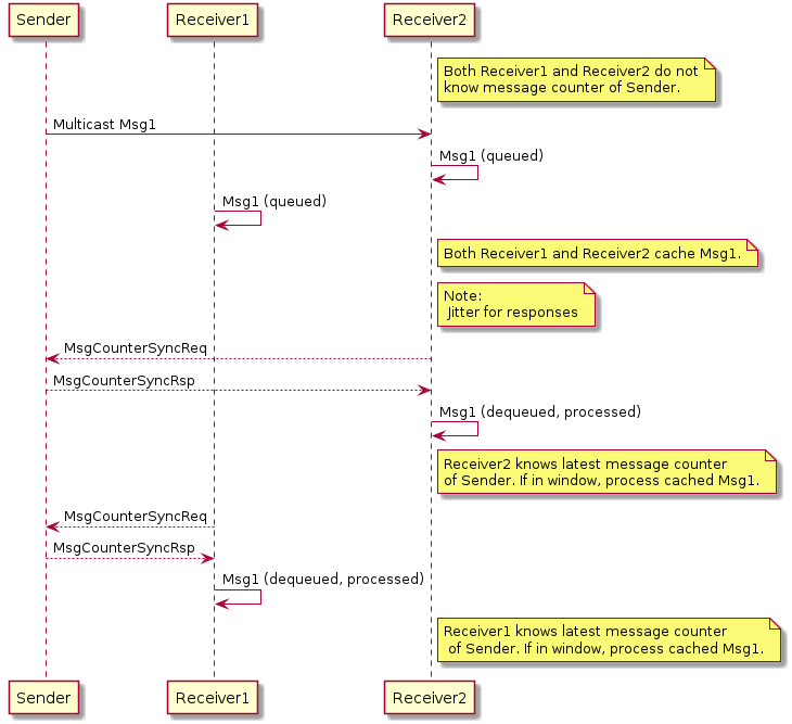
Sequence:
-
Sender:
-
Generates, encrypts and sends Msg1 as a multicast message. Msg1 could be:
-
Regular message that starts encrypted group communication with receivers Receiver1 and Receiver2.
-
-
-
Receivers Receiver1 and Receiver2 each:
-
Receive, decrypt, authenticate, and cache Msg1 message for later processing.
-
Generate, encrypt, and send MsgCounterSyncReq message.
-
-
-
Sender:
-
Receives MsgCounterSyncReq message.
-
Generates, encrypts and sends MsgCounterSyncRsp message.
-
-
R1 and R2 each:
-
Receive, decrypt, process, and verify MsgCounterSyncRsp message from Sender.
-
On verification success: marks Sender 's group key message counter as synchronized.
-
Processes cached Msg1 message.
-
-
4.17. Bluetooth Transport Protocol (BTP)
The Bluetooth Transport Protocol (BTP) provides a TCP-like layer of reliable, connection-oriented data transfer on top of GATT. BTP splits individual Service Data Unit (SDU) messages into multiple BTP segments, which are each transmitted via a single GATT write or indication (as shown in Figure 22, “MATTERoBLE: Matter Message / BTP layering”).
While BTP is a generic protocol, Matter specifically uses BTP to define a Matter-over-Bluetooth Low Energy (MATTERoBLE) Interface. A MATTERoBLE Interface MUST implement BTP as a universally compatible transport mode. A MATTERoBLE Interface SHALL only be used to transport Matter messages as the BTP SDU.
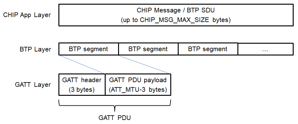
The BTP session handshake allows devices to check BTP protocol version compatibility and exchange other data before a BTP session is established. Once established, this session is used to send and receive BTP SDUs (such as Matter messages) as BTP Message Segments. A BTP session MAY open and close with no effect on the state of the underlying Bluetooth LE connection, except in the case where a BTP session is closed by the Peripheral Device. Either the Peripheral or the Central MAY signal the end of a BTP session by closing the underlying BLE connection.
Due chiefly to constraints put on design by resource-limited BLE chipsets, BTP defines a receive window for each side of a session in units of GATT PDUs. Each GATT Write Characteristic Value (ATT_WRITE_REQ) PDU or Indication (ATT_HANDLE_VALUE_IND) PDU is sent with a sequence number which the receiver uses to acknowledge receipt of each packet at the BTP layer and open its receive window from the sender’s perspective.
4.17.1. BTP Session Interface
Conceptually, an open BTP session is exposed to the next-higher session layer as a full-duplex message stream.
4.17.2. BTP Frame Formats
A BTP Frame consists of an 8-bit header followed by one or more optional fields, as detailed below. BTP uses little endian encoding for any header fields larger than one byte in length.
4.17.2.1. BTP Packet Protocol Data Unit
Table 26, “BTP Packet PDU format” defines the BTP Packet PDU format.
Unused fields SHALL be set to '0'.
| bit 0 | 1 | 2 | 3 | 4 | 5 | 6 | 7 | 8 | 9 | 10 | 11 | 12 | 13 | 14 | 15 |
|---|---|---|---|---|---|---|---|---|---|---|---|---|---|---|---|
- |
H |
M |
- |
A |
E |
- |
B |
[Management Opcode] |
|||||||
[Ack Number] |
[Sequence Number] |
||||||||||||||
[Message Length] |
|||||||||||||||
[Segment Payload]… |
|||||||||||||||
… |
|||||||||||||||
H (Handshake) bit
Set to '0' for normal BTP packets. When set, this bit indicates a BTP handshake packet for session establishment and has a different packet format described below.
M (Management Message) bit
Indicates the presence ('1') or absence ('0') of the Management Opcode field. All segments of a message MUST set this bit to the same value.
B (Beginning Segment) bit
Set to '1' on the first segment of a BTP SDU and set to '0' for all remaining segments of the same BTP SDU. It indicates the presence of the Message Length field.
E (Ending Segment) bit
Set to '1' on the last segment of a BTP SDU and set to '0' for all other segments of the same BTP SDU. A segment MAY have both the Beginning and Ending bits set indicating that a full BTP SDU is included in the message. When set, the segment payload length is equal to the total remaining unreceived message data. When not set, the segment payload length is equal to the maximum allowable BTP session packet size minus header overhead.
Ack Number
Optional field specified in Section 4.17.3.8, “Packet Acknowledgements”.
Sequence Number
Mandatory field for regular data messages specified in Section 4.17.3.6, “Sequence Numbers”.
4.17.2.2. BTP Control Frames
BTP defines different control frame formats depending on the Management Opcode that is in the BTP Packet PDU header. Valid Management Opcodes for BTP Control Frames are defined in Table 27, “BTP Control codes”.
| Management Opcode | Name | Description |
|---|---|---|
0x6C |
Handshake |
Request and response for BTP session establishment |
4.17.2.3. BTP Handshake Request
| bit 0 | 1 | 2 | 3 | 4 | 5 | 6 | 7 | 8 | 9 | 10 | 11 | 12 | 13 | 14 | 15 |
|---|---|---|---|---|---|---|---|---|---|---|---|---|---|---|---|
0 |
H=1 |
M=1 |
0 |
A=0 |
E=1 |
0 |
B=1 |
Management Opcode = 0x6C |
|||||||
Ver[1] |
Ver[0] |
Ver[3] |
Ver[2] |
||||||||||||
Ver[5] |
Ver[4] |
Ver[7] |
Ver[6] |
||||||||||||
Requested ATT_MTU |
|||||||||||||||
Client Window Size |
|||||||||||||||
Ver[i] (Version) nibbles
Used to negotiate the highest version capability between a Device pair. Supported versions are listed once each, newest first, in descending order. Unused version fields are filled with ‘0’.
The following values are defined:
-
0 — Unused field
-
4 — BTP as defined by Matter v1.0
Requested ATT_MTU
Requested ATT_MTU is a 16-bit unsigned integer field containing the size of the GATT PDU (ATT_MTU) that can be received by the sender minus the size of the GATT header (3). This value is obtained via the standard ATT MTU exchange procedure (see Bluetooth® Core Specification 4.2 Vol 3, Part F, Section 3.4.2 "MTU Exchange") and is used to validate that both sides of the BLE connection are using the common minimum value. If BTP is not aware of the negotiated GATT MTU, the value shall be set to '23', indicating the minimum ATT_MTU defined by GATT. If the client has no preference, the value may be set to '0'.
|
Note
|
Each GATT PDU used by the BTP protocol introduces 3 byte header overhead making the maximum BTP Segment Size for the session equal to negotiated ATT_MTU-3. |
Client Window Size
Value of the maximum receive window size supported by the server, specified in units of BTP packets where each packet may be up to 244 bytes in length. This maximum was chosen so a single BTP segment can fit into a single 255 byte BLE link layer PDU, including all headers from the link layer, L2CAP, GATT, and BTP.
4.17.2.4. BTP Handshake Response
| bit 0 | 1 | 2 | 3 | 4 | 5 | 6 | 7 | 8 | 9 | 10 | 11 | 12 | 13 | 14 | 15 |
|---|---|---|---|---|---|---|---|---|---|---|---|---|---|---|---|
0 |
H=1 |
M=1 |
0 |
A=0 |
E=1 |
0 |
B=1 |
Management Opcode = 0x6C |
|||||||
Reserved |
Final Protocol Version |
Selected ATT_MTU (low byte)… |
|||||||||||||
…Selected ATT_MTU (high byte) |
Selected Window Size |
||||||||||||||
4.17.3. BTP GATT Service
4.17.3.1. BTP Channelization
Bluetooth Transport Protocol provides a packetized stream interface over GATT but says nothing about the actual contents of the data packets it transports. The BTP Service UUID is used to specify the actual contents of the packets (see Table 30, “BTP Service UUID”).
| BTP Datagram Contents | BTP Service UUID |
|---|---|
Matter Message frames |
MATTER_BLE_SERVICE_UUID |
While a single BTP connection may exist between a BTP Client and BTP Server, multiple BTP sessions may be established between various peers.
4.17.3.2. BTP GATT Service
The BTP GATT service is composed of a service with three characteristics—C1, C2 and C3 (see Table 31, “BTP GATT service”). The client SHALL exclusively use C1 to initiate BTP sessions by sending BTP handshake requests and send data to the server via GATT ATT_WRITE_CMD PDUs. While a client is subscribed to allow indications over C2, the server SHALL exclusively use C2 to respond to BTP handshake requests and send data to the client via GATT ATT_HANDLE_VALUE_IND PDUs.
| Attribute | Description |
|---|---|
BTP Service |
UUID = MATTER_BLE_SERVICE_UUID |
C1 Characteristic |
UUID = 18EE2EF5-263D-4559-959F-4F9C429F9D11 |
C2 Characteristic |
UUID = 18EE2EF5-263D-4559-959F-4F9C429F9D12 |
C3 Characteristic |
UUID = 64630238-8772-45F2-B87D-748A83218F04 |
For all messages sent from the BTP Client to BTP Server, BTP SHALL use the GATT Write Characteristic Value sub-procedure. For all messages sent from the BTP Server to BTP Client, BTP SHALL use the GATT Indications sub-procedure.
The values of C1 and C2 SHALL both be limited to a maximum length of 247 bytes. This constraint is imposed to align with maximum PDU size when LE Data Packet Length Extensions (DPLE) is enabled on Bluetooth 4.2 hardware. Per Bluetooth® Core Specification 4.2 Vol 3, Part F, Section 3.2.9 "Long Attribute Values", the maximum characteristic value length is 512 bytes. The maximum lengths of C1 and C2 may increase in a future version of the BTP specification to allow higher throughput on BLE connections whose ATT_MTU exceeds 247 bytes.
C3 is an optional characteristic that the server MAY use to include additional data required during the provisioning as defined in Section 5.4.2.5.7, “GATT-based Additional Data”.
BTP Clients SHALL perform certain GATT operations synchronously, including GATT discovery, subscribe, and unsubscribe operations. GATT discovery, subscribe, or unsubscribe SHALL NOT be initiated while the result of a previous operation remains outstanding. This requirement is imposed by GATT protocol.
4.17.3.3. Session Establishment
Before a BTP session can be initiated, a central SHALL first establish a BLE connection to a peripheral. Once a BLE connection has been formed, centrals SHALL assume the GATT client role for BTP session establishment and data transfer, and peripherals SHALL assume the GATT server role. If peripheral supports LE Data Packet Length Extension (DPLE) feature it SHOULD perform data length update procedure before establishing a GATT connection.
Before establishing a BTP session, the GATT client SHOULD perform a GATT Exchange MTU procedure.
After that the BTP Client SHALL execute the GATT discovery procedure. The GATT discovery procedure starts with primary service discovery using either the GATT Discover All Primary Services sub-procedure or the GATT Discover Primary Services by Service UUID sub-procedure.
The BTP Client SHALL perform either the GATT Discover All Characteristics of a Service sub-procedure or the GATT Discover Characteristics by UUID sub-procedure in order to discover the C1 and C2 characteristics.
The BTP Client SHALL perform the GATT Discover All Characteristic Descriptors sub-procedure in order to discover the Client Characteristic Configuration descriptor (CCCD) of C2 characteristic.
To initiate a BTP session, a BTP Client SHALL send a BTP handshake request packet to the BTP Server via a ATT_WRITE_CMD PDU on characteristic C1 of the BTP Service. The handshake request packet SHALL include, a list of BTP protocol versions supported by the client, the client’s GATT ATT_MTU, and the client’s maximum receive window size. The list of supported protocol versions SHALL be sorted in descending numerical order. If the client cannot determine the BLE connection’s ATT_MTU, it SHALL specify a value of '23' (the minimum ATT_MTU supported by GATT) for this field in the handshake request. For a detailed specification of the handshake request binary data format, see Section 4.17.2.3, “BTP Handshake Request”.
After the BTP Client acknowledges delivery of the handshake request packet, upon receipt of a GATT Write Response, the BTP Client SHALL enable indications over C2 characteristics by writing value 0x01 to C2’s Client Characteristic Configuration descriptor as described in Bluetooth® Core Specification 4.2 Vol 3, Part C, Section 10.3.1.1 "Handling GATT Indications and Notifications".
Once the GATT server has received a client’s BTP handshake request and confirmed the client’s subscription to C2, it SHALL send a BTP handshake response to the client via a ATT_HANDLE_VALUE_IND PDU on C2. This response SHALL contain the window size, maximum BTP packet size, and BTP protocol version selected by the server. For a detailed specification of the handshake response binary data format, see Section 4.17.2.4, “BTP Handshake Response”.
The server SHALL select a window size equal to the minimum of its and the client’s maximum window sizes. Likewise, the server SHALL select a maximum BTP Segment Size for the BLE connection by taking the minimum of 244 bytes (the maximum characteristic value length of C1 and C2), server’s ATT_MTU-3 and ATT_MTU-3 as declared by the client.
The server SHALL select a BTP protocol version that is the newest which it and the client both support, where newer protocol version numbers are strictly larger than those of older versions. The version number returned in the handshake response SHALL determine the version of the BTP protocol used by client and server for the duration of the session.
If the server determines that it and the client do not share a supported BTP protocol version, the server SHALL close its BLE connection to the client. When a client sends a handshake request, it SHALL start a timer with a globally-defined duration of BTP_CONN_RSP_TIMEOUT seconds. If this timer expires before the client receives a handshake response from the server, the client SHALL close the BTP session and report an error to the application. Likewise, a server SHALL start a timer with the same duration when it receives a handshake request from a client. If this timer expires before the server receives a subscription request on C2, the server SHALL close the BTP session and report an error to the application. The state machine in Figure 23, “BTP session handshake” illustrates the function of these timers as part of the BTP session establishment procedure.
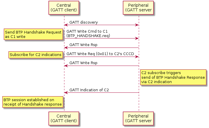
4.17.3.4. Data Transmission
Once a BTP session has been established, the next-higher-layer application on both peers may use this BLE connection to send and receive data via GATT writes or indications, according to a peer’s GATT role. Clients SHALL exclusively use GATT Write Characteristic Value sub-procedure to send data to servers and servers SHALL exclusively use GATT Indication sub-procedure to send data to clients.
All BTP packets sent on an open BLE connection SHALL adhere to the BTP Packet PDU binary data format specified in BTP Frame Formats. All BTP packets SHALL include a header flags byte and an 8-bit unsigned sequence number. All other packet fields are optional. These optional fields include an 8-bit unsigned received packet acknowledgement number, 16-bit unsigned buffer length indication, and variable-length buffer segment payload.
This section is defined entirely within the scope of a single BTP session. Concurrent BTP sessions between the same peer and multiple remote hosts SHALL maintain separate and independent acknowledgement timers, sequence numbers, and receive windows.
4.17.3.5. Message Segmentation and Reassembly
When the session layer (that is, MATTERoBLE) sends a Matter Message as a BTP SDU over a BTP session, that BTP SDU SHALL be split into ordered, non-overlapping BTP segments so the set of all BTP segments may be reassembled into the original BTP SDU (see Figure 22, “MATTERoBLE: Matter Message / BTP layering”). Each BTP segment SHALL be prepended with a BTP packet header and sent as the payload of a single GATT PDU. If a BTP SDU is split into more than one BTP segment, the BTP segments SHALL be sent in order of their position in the original BTP SDU, starting with the BTP segment at the buffer’s head.
At any point in time, only one BTP SDU may be transmitted in each direction over a BTP session. The transmission of BTP segments of any two BTP SDUs SHALL not overlap. If the application attempts to send one BTP SDU while transmission of another BTP SDU is in progress, the new BTP SDU SHALL be appended to a first-in, first-out queue. The next BTP SDU SHALL be dequeued from this queue and transmitted once transmission of the current BTP SDU completes, that is, once all BTP segments of the current BDP SDU have been transmitted and received by the peer via GATT.
The first BTP segment of a BTP SDU sent over a BTP session SHALL have its Beginning Segment header flag set to indicate the beginning of a new BTP SDU (see Table 26, “BTP Packet PDU format”). The presence of this flag SHALL indicate the further presence of a 16-bit unsigned integer field, the Message Length, that provides the receiver with the total length of the BTP SDU. The last BTP segment for a given BTP SDU SHALL have its Ending Segment flag set to indicate the end of the transmitted BTP SDU. A BTP packet that bears an unsegmented BTP SDU—that is, a BTP SDU small enough to fit into a single BTP segment—SHALL have both its Beginning Segment and Ending Segment flags set.
The size of a single BTP SDU sent via BTP is limited to 64KB, that is, the maximum size of the Message Length field in the BTP packet header. The number of segments used to send a buffer is unlimited and delimited by the Beginning Segment and Ending Segment bits in the BTP packet header. The upper layer imposes more stringent requirements over the maximum SDU size, such as Section 4.4.4, “Message Size Requirements”.
The length of the data payload in each BTP segment whose Ending Segment bit is not set SHALL be equal to the session’s maximum BTP packet size minus the size of that packet’s header. If a packet’s Ending Segment bit is set, the length of its BTP segment data payload SHALL equal the size of the original BTP SDU minus the total size of all previously transmitted BTP segments of that BTP SDU. In this way, the length of a SDU’s last BTP segment is implied by its size.
Once a peer receives a complete set of BTP segments, it SHALL reassemble them in the order received, and verify that the reassembled BTP SDU’s total length matches that specified by the Beginning Segment’s Message Length value. If they match, the receiver SHALL pass the reassembled BTP SDU up to the next-higher-layer. If the reassembled buffer’s length does not match that specified by the sender, or if received BTP segment payload size would exceed the maximum BTP packet size, or receiver receives an Ending Segment without the presence of a previous Beginning Segment, or a Beginning Segment when another BTP SDU’s transmission is already in progress, the receiver BTP SHALL close the BTP session and report an error to the application.
4.17.3.6. Sequence Numbers
All BTP packets SHALL be sent with sequence numbers, regardless of whether they contain SDU segments (for example, a packet acknowledgement with no attached segment payload). The purpose of sequence numbers is to facilitate the BTP receive window. A BTP sequence number SHALL be defined as an unsigned 8-bit integer value that monotonically increments by 1 with each packet sent by a given peer. A sequence number incremented past 255 SHALL wrap to zero.
Sequence numbers SHALL be separately defined for either direction of a BTP session. The sequence number of the first packet sent by the client after completion of the BTP session handshake SHALL be zero. The server’s BTP handshake response bears an implied sequence number of zero because it occupies a slot in the client’s receive window. The client acknowledges the server’s BTP handshake response with an acknowledgement sequence of zero. For this reason, the sequence number of the first data packet sent by the server after completion of the BTP session handshake SHALL be 1.
Peers SHALL check to ensure that all received BTP packets properly increment the sender’s previous sequence number by 1. If this check fails, the peer SHALL close the BTP session and report an error to the application.
4.17.3.7. Receive Windows
The purpose of the receive window is to enable flow control at the GATT session layer between BTP peers.
Flow control is required at the GATT transport layer for embedded platforms that use "minimal" BLE chipsets. These platforms may have limited space on the host processor to receive packets from their BLE chipsets. In the case of some dual-chip architectures, writes and indications are received and confirmed by the BLE chip with no input from the host processor. When the BLE chip sends the result of a received GATT PDU to the host processor, that payload and the corresponding BTP packet will be permanently lost if the host does not have enough space to receive it. For this reason, knowledge of a remote host’s ability to reliably receive GATT PDUs is presented at the transport layer in the form of the BTP receive window.
Both peers in a BTP session SHALL define a receive window, where the window’s size indicates the number of GATT PDUs (that is, BTP segments) a peer can reliably receive and store without session-layer acknowledgment. A maximum window size SHALL be established for both peers as part of the BTP session handshake. To prevent sequence number wrap-around, the largest maximum window size any peer may support is 255.
Both peers SHALL maintain a counter to reflect the current size of the remote peer’s receive window. Each peer SHALL decrement this counter when it sends a packet via GATT write or indication and increment this counter when a sent packet is acknowledged.
If a local peer’s counter for a remote peer’s receive window is zero, the window SHALL be considered closed, and the local peer SHALL NOT send packets until the window reopens (is incremented above zero). When a closed window reopens, a local peer SHALL immediately resume any pending BTP packet transmission.
A local peer SHALL also not send packets if the remote peer’s receive window has one slot open and the local peer does not have a pending packet acknowledgement. This is to avoid the situation where the receive windows of both peers are full and neither can send an acknowledgement to reopen its window for the other. Because the server’s handshake response bears an implicit BTP sequence number of zero, a server SHALL initialize its counter for the client’s receive window size at (negotiated maximum window size - 1). A client SHALL initialize its counter for the server’s receive window at the negotiated maximum window size.
Both peers SHALL also keep a counter of their own receive window size based on the sequence number difference between the last packet they received and the last packet they acknowledged. This counter is used to proactively send early packet acknowledgements when a peer’s own receive window is about to close. See Section 4.17.3.8, “Packet Acknowledgements” for details.
An example scenario involving BTP receive windows is depicted in Figure 24, “Example receive window scenario”, complete with packet acknowledgements as specified in Section 4.17.3.8, “Packet Acknowledgements”. In this scenario, the client transmits a three-segment buffer to the server once it receives the server’s handshake request. The handshake request occupies one slot in the client’s initial receive window. The server’s initial receive window is empty. Both client and server have a maximum window size of 4.
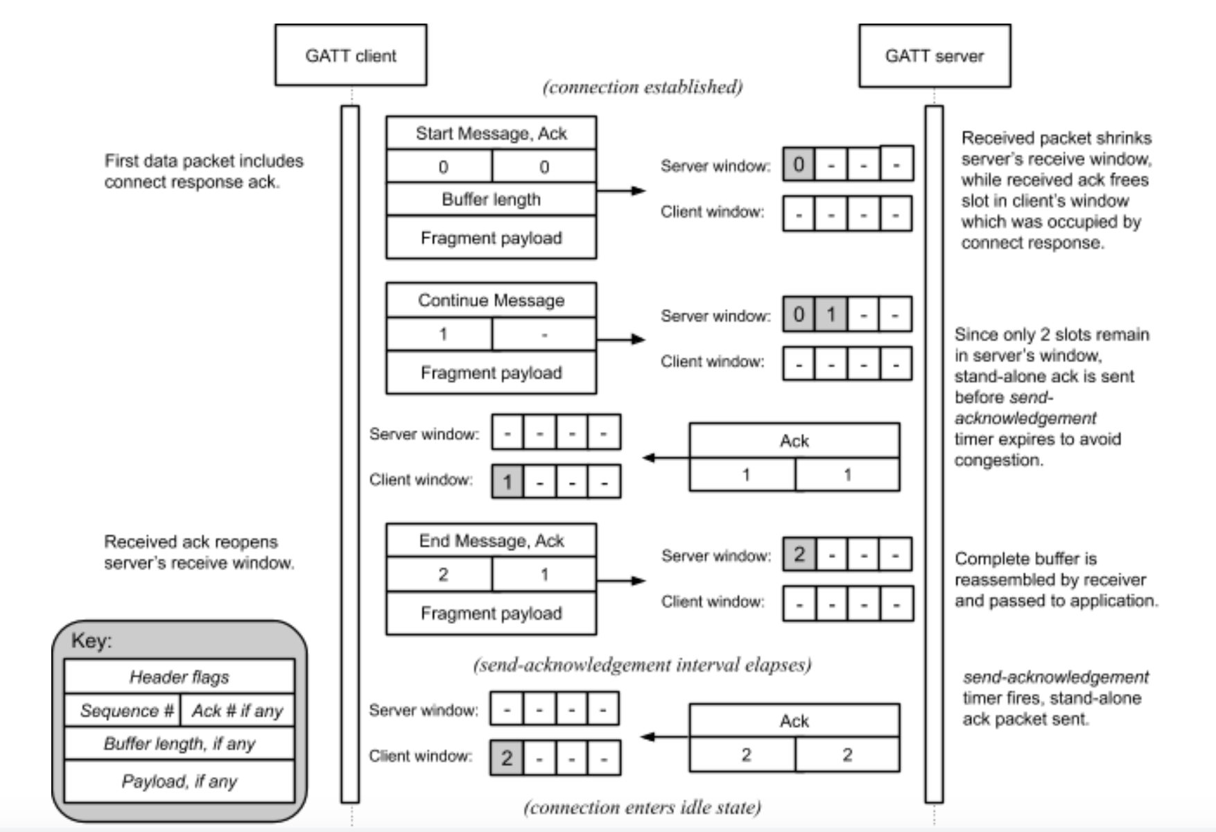
4.17.3.8. Packet Acknowledgements
The purpose of sequence numbers and packet receipt acknowledgements is to support the BTP receive window and provide a keep-alive signal when a session is idle to affirm the health and continued operation of a remote BTP stack.
Per BTP Frame Formats, BTP packet receipt acknowledgements SHALL be received as unsigned 8-bit integer values in the header of a BTP packet. The value of this field SHALL indicate the sequence number of the acknowledged packet.
Acknowledgement of a sequence number indicates acknowledgement of the previous sequence number, if it too is unacknowledged. By induction, acknowledgement of a given packet implies acknowledgement of all packets received on the same BTP session prior to the acknowledged packet.
An acknowledgement is invalid if the acknowledged sequence number does not correspond to an outstanding, unacknowledged BTP packet sequence number. In contrast to TCP, BTP acks are not "free." A stand-alone ack—that is, a BTP packet that contains a packet receipt acknowledgement value but no buffer segment payload—consumes a slot in a remote peer’s window just like any other packet. Stand-alone acknowledgement packets SHALL be acknowledged by a remote peer. The implications of this are examined in Section 4.17.3.9, “Idle Connection State”.
Each peer SHALL maintain an acknowledgement-received timer. When a peer sends any BTP packet, it SHALL start this timer if it is not already running. The timer’s duration SHALL be globally defined as BTP_ACK_TIMEOUT seconds, referred to as the acknowledgement timeout interval.
A peer SHALL restart its acknowledgement-received timer when a valid acknowledgement is received for any but its most recently sent unacknowledged packet. A peer SHALL stop its acknowledgement-received timer if it receives an acknowledgement for its most recently sent unacknowledged packet. If a peer’s acknowledgement-received timer expires, or if a peer receives an invalid acknowledgement, the peer SHALL close the BTP session and report an error to the application.
Because the server’s handshake response bears an implicit BTP sequence number of zero, a server SHALL start its acknowledgement-received timer when it sends a handshake response.
Each peer SHALL also maintain a send-acknowledgement timer. When it receives any BTP packet, a peer SHALL record the packet’s sequence number as the corresponding BTP session’s pending acknowledgement value and start the send-acknowledgement timer if it is not already running. The timer’s duration timer SHALL be defined as any value less than one-half the acknowledgement timeout interval. This ensures that on a healthy BLE connection, a peer will always receive acknowledgements for sent packets before its acknowledgement-received timer expires.
A peer SHALL stop its send-acknowledgement timer when any pending acknowledgement is sent, either as a stand-alone BTP packet or piggybacked onto an outgoing buffer segment. If this timer expires and the peer has a pending acknowledgement, the peer SHALL immediately send that acknowledgement. If the peer sends any packet before this timer expires, it SHALL piggyback any pending acknowledgement on the transmitted packet and stop the send-acknowledgement timer.
Because the server’s handshake response bears an implicit BTP sequence number of zero, a client SHALL set its pending acknowledgement value to zero and start its send-acknowledgement timer when it receives the server’s a handshake response. Operation of the send-acknowledgement and acknowledgement-received timers is illustrated in Figure 26, “BTP session lifecycle for Central acting as GATT Client” in Section 4.17.3.11, “Protocol State Diagrams”.
If a peer detects that its receive window has shrunk to two or fewer free slots, it SHALL immediately send any pending acknowledgement as a stand-alone BTP packet. This prevents the session from stalling in the interval between when a peer’s receive window becomes empty and when its send-acknowledgement timer would normally fire.
4.17.3.9. Idle Connection State
When neither side of a BTP session has data to send, BTP packets will still be exchanged every send-acknowledgement interval due to acknowledgements generated by the receipt of previous data or stand-alone acknowledgement packets, as discussed in Section 4.17.3.8, “Packet Acknowledgements”. The behavior of the acknowledgement-received timer in this scenario doubles as a keep-alive mechanism, as it will cause a peer to close a BLE connection automatically if the remote BTP stack crashes or becomes unresponsive. This scenario is illustrated in Figure 25, “Idle connection scenario”.
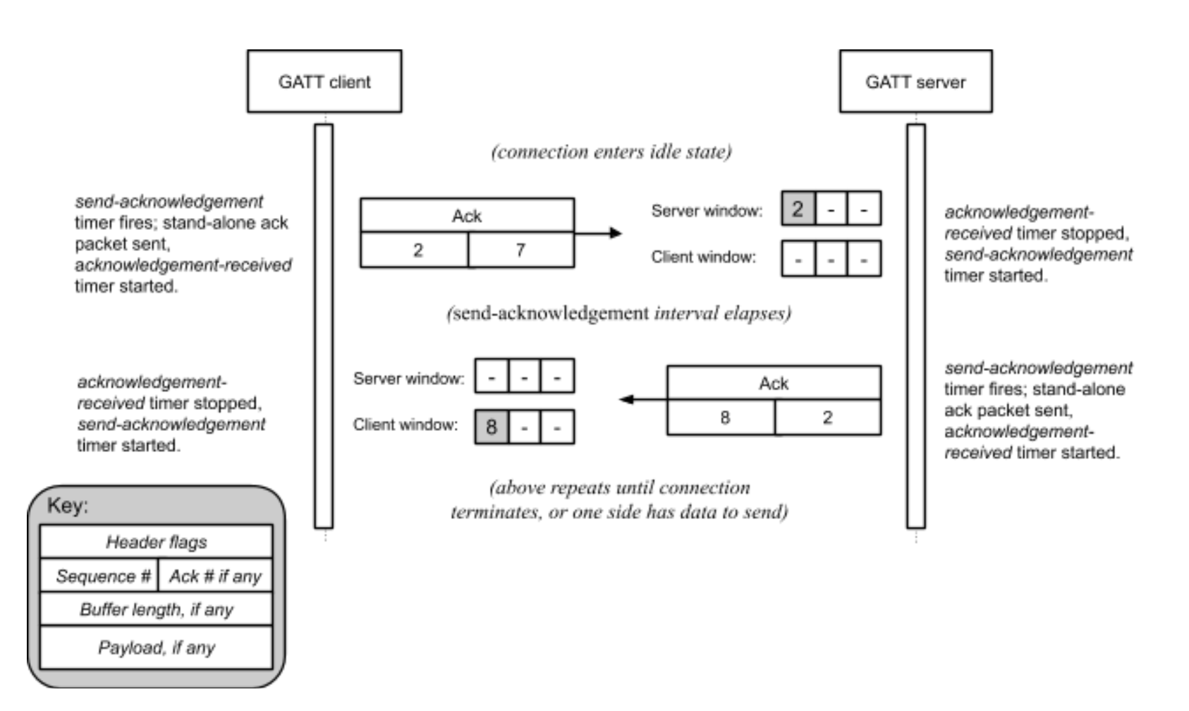
4.17.3.10. Connection Shutdown
To close a BTP session, a GATT client SHALL unsubscribe from characteristic C2. The GATT server SHALL take this action to indicate closure of any BTP session open to the client.
If a BTP Server needs to close the BTP session, it SHALL terminate its BLE connection to the client.
4.17.3.11. Protocol State Diagrams
Figure 26, “BTP session lifecycle for Central acting as GATT Client” shows the state machine for BTP session management of a BTP Client Device.
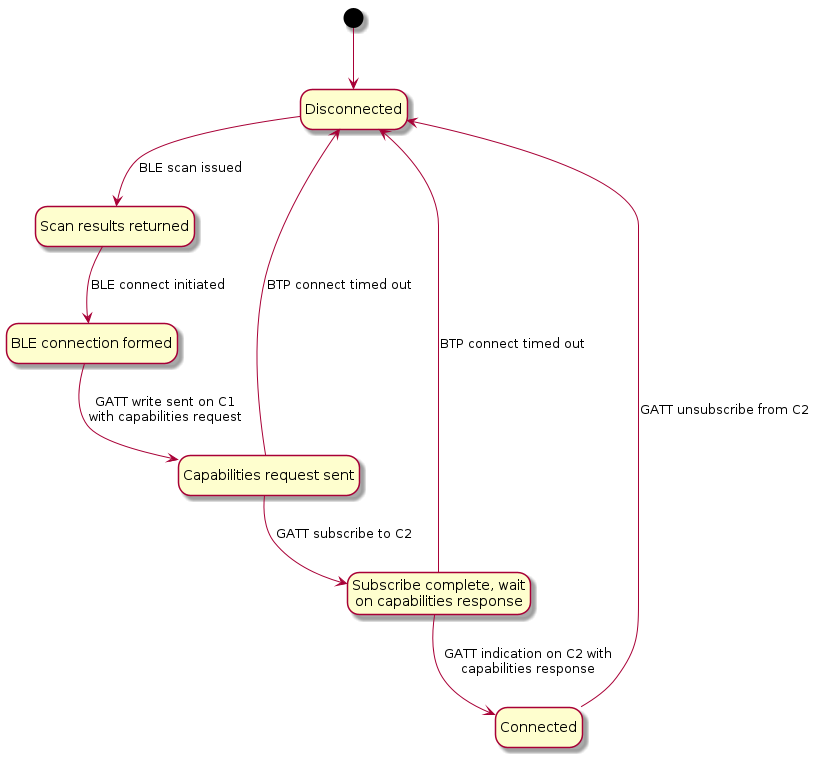
Figure 27, “BTP session lifecycle for Peripheral acting as GATT Server” shows the state machine for BTP session management of a BTP Server Device.
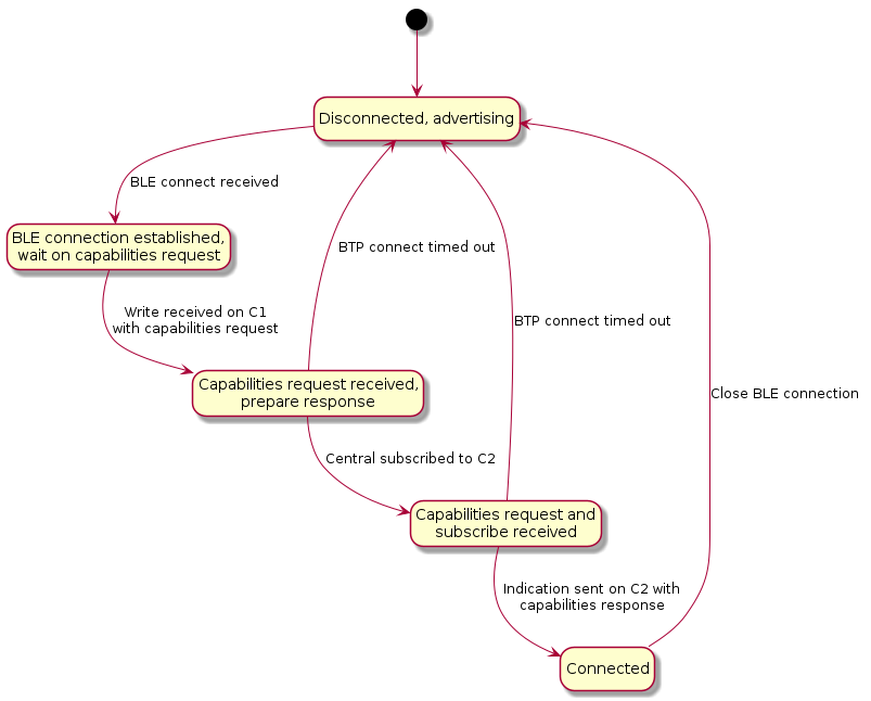
Note that in Figure 27, “BTP session lifecycle for Peripheral acting as GATT Server”, the state machine is identical for GATT clients and servers with the distinction that clients send data to servers via confirmed writes, and servers send data to clients via indications.
Figure 28, “State diagram for BTP session post-establishment” shows the state machine for BTP session maintenance at the protocol level, including liveliness enforcement through keep alive messages and automatic teardown if acknowledgements are received before the timeout.
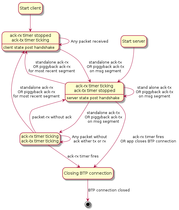
4.17.4. Parameters and Constants
Table 32, “Glossary of constants” is a glossary of constants used in this chapter, along with a brief description and the default for each constant.
| Constant Name | Description | Default |
|---|---|---|
BTP_CONN_RSP_TIMEOUT |
The maximum amount of time after sending a BTP Session Handshake request to wait for a BTP Session Handshake response before closing the connection. |
5 seconds |
BTP_ACK_TIMEOUT |
The maximum amount of time after receipt of a segment before a stand-alone ACK must be sent. |
15 seconds |
BTP_CONN_IDLE_TIMEOUT |
The maximum amount of time no unique data has been sent over a BTP session before the Central Device must close the BTP session. |
30 seconds |
4.17.5. Bluetooth SIG Considerations
The UUID is provided by Bluetooth SIG, Inc. and may only be used by its members in compliance with all terms and conditions of use issued by the Bluetooth SIG, Inc. For more information, visit https://www.bluetooth.com/specifications/assigned-numbers/16-bit-uuids-for-sdos.
Use of the Bluetooth extensions feature of this specification and specifically the MATTER_BLE_SERVICE_UUID is strictly prohibited unless the product is certified by both the Bluetooth SIG and the Connectivity Standards Alliance by a member of good standing of both organizations.
| Constant Name | Description | Value |
|---|---|---|
MATTER_BLE_SERVICE_UUID |
The UUID for the Matter-over-BLE service as assigned by the Bluetooth SIG. |
0xFFF6 |
5. Commissioning
5.1. Onboarding Payload
The purpose of this section is to define the contents of the Onboarding Payload needed to allow onboarding a device into a Matter network. It also specifies the representation and encoding of said payload as a QR Code, as a manually entered code, and as content in an NFC tag.
5.1.1. Onboarding Payload Contents
The Onboarding Payload is composed of required and optional information which will be used by the Commissioner to ensure interoperability between commissioners and devices and provide a consistent user experience. Some or all of this content will be encoded into different formats, some human-readable (such as numeric string) and machine-readable (such as QR code and NFC) formats for printing or display on or integration into the device. The following are the elements that may be used in an Onboarding Payload for a Matter device.
5.1.1.1. Version
A version indication provides versioning of the payload and SHALL be included. Version for machine-readable formats is 3 bits with an initial version of 0b000. Version for Manual Pairing Code is 1 bit with an initial version of 0b0.
Rationale: This allows a way to introduce changes to the payload as needed going into the future.
5.1.1.2. Vendor ID and Product ID
Vendor ID and Product ID, each a 16-bit value, SHALL be included in machine-readable formats and MAY be included in the Manual Pairing Code.
Rationale: This allows a way to identify the make and model of the device, which is used further during the commissioning flow, such as during the Device Attestation procedure.
These unique identifiers also help to retrieve device model metadata like product name, product description, and firmware update URL from the Distributed Compliance Ledger, as well as information relevant to the commissioning flow (see Section 5.7, “Device Commissioning Flows”).
5.1.1.3. Custom Flow
A 2-bit unsigned enumeration specifying the Device Commissioning Flow SHALL be included in machine-readable formats. For the encoding of Custom Flow in the Manual Pairing Code, see Section 5.1.4.1.2, “Custom Flow for Manual Pairing Code”.
Rationale: This guides the Commissioner as to whether steps are needed before commissioning can take place.
-
A value of
0indicates that no steps are needed (apart from powering the device). -
A value of
1indicates that user interaction with the device (pressing a button, for example) is required before commissioning can take place. The specific steps required can be found in the CommissioningModeInitialStepsHint field of the Distributed Compliance Ledger for the given Vendor ID and Product ID. -
A value of
2indicates that an interaction with a service provided by the manufacturer is required for initial device setup before it is available for commissioning by any Commissioner. The URL for this service can be found in the CommissioningCustomFlowUrl field of the Distributed Compliance Ledger for the given Vendor ID and Product ID.
5.1.1.4. Discovery Capabilities Bitmask
An 8-bit capabilities bitmask SHALL be included in machine-readable formats.
Rationale: The Discovery Capabilities Bitmask contains information about the device’s available technologies for device discovery (see Section 5.4, “Device Discovery”).
5.1.1.5. Discriminator value
A Discriminator SHALL be included as a 12-bit unsigned integer, which SHALL match the value which a device advertises during commissioning. To easily distinguish between advertising devices, this value SHOULD be different for each individual device.
For machine-readable formats, the full 12-bit Discriminator is used. For the Manual Pairing Code, only the upper 4 bits out of the 12-bit Discriminator are used.
Rationale: The Discriminator value helps to further identify potential devices during the setup process and helps to improve the speed and robustness of the setup experience for the user.
5.1.1.6. Passcode
A Passcode SHALL be included as a 27-bit unsigned integer, which serves as proof of possession during commissioning. The 27-bit unsigned integer encodes an 8-digit decimal numeric value, and therefore shall be restricted to the values 0x0000001 to 0x5F5E0FE (00000001 to 99999998 in decimal), excluding the invalid Passcode values.
Rationale: The Passcode establishes proof of possession and is also used as the shared secret in setting up the initial secure channel over which further onboarding steps take place.
5.1.1.7. TLV Data
Variable-length TLV data using the TLV format MAY be included in machine-readable formats providing optional information. More details about the TLV can be found in Section 5.1.5, “TLV Content”.
5.1.2. Onboarding Material Representation
In order for the users of Matter products to recognize the onboarding material, and be able to use it easily, it is important to keep the representations of the onboarding material unified and of certain minimum size. To support this the Matter Brand Guidelines specify the characteristics like composition, colors, font, font size, QR Code size and digit-grouping of the Manual Pairing code.
When the onboarding material is printed on product or packaging material it SHALL follow the Matter Brand Guidelines.
Other representations (product display, app, etc) of the onboarding material SHOULD follow the Matter Brand Guidelines.
5.1.3. QR Code
The Onboarding Payload MAY be included on (or with) a device in the form of a QR code. The following sections detail the content, encoding, and formatting of the QR code.
5.1.3.1. Payload
The content of the QR code consists of the concatenation of a prefix string and a Base-38-encoded string containing the required and optional TLV content:
QR code string := <prefix><base-38-content>
Base-38 Content
The required content of the QR code is composed of a Packed Binary Data Structure containing elements of the Onboarding Payload as detailed below. The resulting data is Base-38 encoded (with a specific alphabet) to form a string compatible with alphanumeric QR encoding.
Packed Binary Data Structure
Individual data elements SHALL be placed into the structure in the order detailed in the table below. Elements being packed are not necessarily byte- or word-aligned. The resulting packed structure is presented to the encoder as a multi-byte array (see Encoding section below), which SHALL be padded with '0' bits at the end of the structure to the nearest byte boundary.
The bits of each fixed-size value are placed in the packed binary data structure in order from least significant to most significant. If TLV Data is included, it is appended to the end of the packed binary data.
For example, the first elements in the table below SHALL be packed into the first bytes of the data array as pictured:
| lsb Byte 0 msb | Byte 1 | Byte 2 | Byte 3 | … | ||||||||||||||||||||||||||||||
|---|---|---|---|---|---|---|---|---|---|---|---|---|---|---|---|---|---|---|---|---|---|---|---|---|---|---|---|---|---|---|---|---|---|---|
0 |
7 |
0 |
7 |
0 |
7 |
0 |
7 |
0 |
||||||||||||||||||||||||||
version |
Vendor ID |
Product ID |
||||||||||||||||||||||||||||||||
0 |
2 |
0 |
15 |
0 |
15 |
|||||||||||||||||||||||||||||
| Onboarding Payload Element | Size (bits) | Required | Notes |
|---|---|---|---|
Version |
3 |
Yes |
3-bit value specifying the QR code payload version. |
Vendor ID |
16 |
Yes |
|
Product ID |
16 |
Yes |
|
Custom Flow |
2 |
Yes |
Device Commissioning Flow |
Discovery Capabilities Bitmask |
8 |
Yes |
Defined in table below. |
Discriminator |
12 |
Yes |
12-bit as defined in Discriminator |
Passcode |
27 |
Yes |
|
Padding |
4 |
Yes |
Bit-padding of '0’s to expand to the nearest byte boundary, thus byte-aligning any TLV Data that follows. |
TLV Data |
Variable |
No |
Variable length TLV data. Zero length if TLV is not included. This data is byte-aligned. |
| Bit | Size (bits) | Description |
|---|---|---|
0 (lsb) |
1 |
Soft-AP: |
1 |
1 |
BLE: |
2 |
1 |
On IP network: |
3..7 |
5 |
Reserved (SHALL be 0) |
TLV Data
The TLV data is an optional, variable-length payload. The payload is composed of one or more TLV-encoded elements as defined in detail below in the TLV Content section.
Encoding
The Packed Binary Data Structure is Base-38 encoded (with a specific alphabet) to produce an alphanumeric string suitable for use as a QR code payload.
Alphabet
The Base-38 alphabet to be employed is composed of a subset of the 45 available characters (A-Z0-9$%*+./ :-) in the QR code for alphanumeric encoding as defined by ISO/IEC 18004:2015, with characters $, %, *, +, /, <space>, and : removed.
| Code | Character | Code | Character | Code | Character | Code | Character | Code | Character |
|---|---|---|---|---|---|---|---|---|---|
00 |
0 |
09 |
9 |
18 |
I |
27 |
R |
36 |
- |
01 |
1 |
10 |
A |
19 |
J |
28 |
S |
37 |
. |
02 |
2 |
11 |
B |
20 |
K |
29 |
T |
||
03 |
3 |
12 |
C |
21 |
L |
30 |
U |
||
04 |
4 |
13 |
D |
22 |
M |
31 |
V |
||
05 |
5 |
14 |
E |
23 |
N |
32 |
W |
||
06 |
6 |
15 |
F |
24 |
O |
33 |
X |
||
07 |
7 |
16 |
G |
25 |
P |
34 |
Y |
||
08 |
8 |
17 |
H |
26 |
Q |
35 |
Z |
Method
Base-38 encoding is achieved by employing a simplified strategy where every 3 bytes (24 bits) of binary source data are encoded to 5 characters of the Base-38 alphabet.
Data from the Packed Binary Data Structure are encoded starting with the first byte of the structure. Three-byte chunks are formed into a 24-bit unsigned integer for encoding as follows:
The 24-bit value is subsequently converted to Base-38 radix using the alphabet above to produce a 5-character substring, with the least-significant character appearing first (little-endian).
If a single byte of binary source data remains, it shall be converted to Base-38 radix using the alphabet above to produce a 2-character substring, with the least-significant character appearing first.
If two bytes of binary source data remains, they shall be formed into a 16-bit unsigned integer for encoding as follows:
This 16-bit value is subsequently converted to Base-38 radix using the alphabet above to produce a 4-character substring, with the least-significant character appearing first.
The final encoded string is a result of concatenation of all substrings, with the first-encoded substring appearing at the beginning of the concatenated string.
5.1.3.2. QR Code Format
The format selection, which includes the QR code Version and ECC levels as well as size and color, MAY be tailored to the requirements of the manufacturer and their respective product, provided it meets the following requirements:
QR code Version and Encoding
The QR code generated, as defined in ISO/IEC 18004:2015, SHALL be of Version 1 or higher, using alphanumeric encoding. The size of the payload implies a minimum Version, though a higher Version may be needed to allow a higher ECC level. For example, a minimum payload of 22 alphanumeric characters (19 base-38-encoded characters from the packed binary structure plus 3 prefix characters) can be fit into a Version 1 with ECC=L, but for ECC=M, Q or H, the same payload requires a Version 2 QR code. This allows the Manufacturer to balance between ECC, pixel size and overall size.
Example QR Code Sizes and Payloads
| QR Code Version | Module Size | ECC Level | Alphanumeric capacity (chars) | Total available payload, excluding prefix (bits) | Available payload for TLV data (bits) |
|---|---|---|---|---|---|
1 |
21x21 |
L |
25 |
104 |
16 |
2 |
25x25 |
L |
47 |
208 |
120 |
M |
38 |
168 |
80 |
||
Q |
29 |
120 |
32 |
||
3 |
29x29 |
L |
77 |
352 |
264 |
M |
61 |
272 |
184 |
||
Q |
47 |
208 |
120 |
||
H |
35 |
152 |
64 |
||
4 |
33x33 |
L |
114 |
528 |
440 |
M |
90 |
416 |
328 |
||
Q |
67 |
304 |
216 |
||
H |
50 |
224 |
136 |
||
5 |
37x37 |
L |
154 |
720 |
632 |
M |
122 |
568 |
480 |
||
Q |
87 |
400 |
312 |
||
H |
64 |
288 |
200 |
|
Note
|
Version 1 codes with ECC levels M, Q, and H and version 2 codes with ECC level H have insufficient capacity |
|
Note
|
Total available payload, excluding prefix = (trunc((N-3) / 5) * 24) where N is the number of alphanumeric characters which fit in the QR code. This formula uses N-3 to account for the prefix characters, and then determines how many groups of 5 base-38-encoded characters can fit; each such group carrying 24 bits of payload.This formula fills groups of 5 characters after the MT: prefix. If there are 2,3 or 4 characters left after these groups, an additional 8 bits (for 2,3 characters) or 16 bits (for 4 characters) of TLV data can be accommodated. So the entries in the table take this into account.Available payload for TLV data = (Total available payload, excluding prefix - 88) since the minimum payload for the Packed Binary Data Structure is 84 bits before padding, or 88 bits with padding.
|
ECC Level
The QR code SHOULD employ level M or higher ECC.
|
Note
|
A higher level ECC does not help against typical 'reading' issues like shiny surfaces, bad contrast or issues with camera resolution/focus, and lack of camera-app processing dedicated for QR codes. Therefore, in certain situations ECC=L MAY be used as well (e.g. to prevent having to move to a higher Version to fit the payload). |
5.1.4. Manual Pairing Code
This section describes the content and format of the Manual Pairing Code, which can be used in certain situations next to or instead of the QR code described above.
5.1.4.1. Content
Payload
The payload of the Manual Pairing Code consists of the following required and optional data elements.
| Element | Size (bits) | Required | Notes |
|---|---|---|---|
VERSION |
1 |
Yes |
Shall be 0 |
VID_PID_PRESENT |
1 |
Yes |
0: no Vendor ID and Product ID present in Manual Pairing Code |
DISCRIMINATOR |
4 |
Yes |
4 Most-significant bits of the 12-bits Discriminator described above |
PASSCODE |
27 |
Yes |
Same as 27-bit Passcode described above |
VENDOR_ID |
16 |
No |
Needed only to support devices that need a user-intent or vendor specific flow before commissioning (i.e. a non-zero Custom Flow value). |
PRODUCT_ID |
16 |
No* |
* This element SHALL be included if and only if the VENDOR_ID element is present. |
The Vendor ID and Product ID elements are optional. Including these may provide additional information for the setup flow at the expense of a substantially longer Manual Pairing Code.
Custom Flow for Manual Pairing Code
The encoding for Manual Pairing Code does not have a dedicated field for Custom Flow, as exists in the Packed Binary Data Structure. Instead, this information is encoded in the following way:
-
For Standard commissioning flow, the variant of Manual Pairing Code without Vendor ID and Product ID SHALL be used. A commissioner encountering such Manual Pairing Code SHALL assume it is a "standard flow" device.
-
For User-intent commissioning flow and Custom Commissioning flow, the variant of Manual Pairing Code with Vendor ID and Product ID SHALL be used. For this case, a commissioner SHOULD use Vendor ID and Product ID to lookup the CommissioningCustomFlow field in the Distributed Compliance Ledger to determine which of these values applies for this Vendor ID and Product ID combination.
Encoding
The required and optional elements, along with a check digit, are encoded into either an 11-digit or 21-digit decimal numeric string, depending on whether the optional Vendor and Product ID information is included.
Method
Each group of digits in the Pairing Code SHALL be encoded as described in the table below. The left-most digit of the entire string SHALL be represented by DIGIT[1]. Groups of multiple digits SHALL be encoded such that the most-significant digit appears first (left-most).
| Digit | Contents | Encoding | Notes |
|---|---|---|---|
1 |
- Version 0 |
DIGIT[1] := |
Allows first digit typed/spoken to determine version and VID/PID present. |
2..6 |
- 3rd and 4th ms-bits of Discriminator |
DIGIT[2..6] := |
Yields a 5-digit decimal number from 00000 to 65535 (0xFFFF/16 bits) |
7..10 |
- 13 ms-bits of PASSCODE |
DIGIT[7..10] := |
Yields a 4-digit decimal number from 0000 to 8191 (0x1FFF/13 bits) |
11 |
- Check Digit |
DIGIT[11] := |
See Check Digit section for encoding |
| Digit | Contents | Encoding | Notes |
|---|---|---|---|
1 |
- Version 0 |
DIGIT[1] := |
Allows first digit typed/spoken to determine version and VID/PID present. |
2..6 |
- 3rd and 4th ms-bits of Discriminator |
DIGIT[2..6] := |
Yields a 5-digit decimal number from 00000 to 65535 (0xFFFF/16 bits) |
7..10 |
- 13 ms-bits of PASSCODE |
DIGIT[7..10] := |
Yields a 4-digit decimal number from 0000 to 8191 (0x1FFF/13 bits) |
11..15 |
- Vendor ID |
DIGIT[11..15] := |
Yields a 5-digit decimal number from 00000 to 65535 (0xFFFF/16 bits) |
16..20 |
- Product ID |
DIGIT[16..20] := |
Yields a 5-digit decimal number from 00000 to 65535 (0xFFFF/16 bits) |
21 |
- Check Digit |
DIGIT[21] := |
See Check Digit section for encoding |
Check Digit
The CHECK_DIGIT element is a single decimal digit computed across all of the preceding digits of the Pairing Code using the Verhoeff algorithm.
5.1.4.2. Copying between applications
When the Manual Pairing Code is presented in an application within a multi-function device, such as an application on a smartphone, it SHOULD provide a mechanism such as a copy button to allow easy conveyance of the information to other commissioners on the same device. When a Commissioner is implemented as an application within a multi-function device, such as an application on a smartphone, it SHOULD provide a mechanism such as a paste button to allow easy conveyance of the information from an administrator on the same device.
5.1.5. TLV Content
A variable-length TLV Data section MAY be encoded into the Packed Binary Data Structure. The TLV section MAY consist of manufacturer-specific information elements and/or elements common to Matter, encoded using TLV. All elements SHALL be housed within an anonymous top-level structure container.
5.1.5.1. Manufacturer-specific Elements
Manufacturer-specific elements SHALL be tagged with context-specific tags that have semantics which are defined by the vendor for use in the products using their Vendor ID, and SHALL use tag numbers 0x80 to 0xFF.
Tag numbers 0x00 to 0x7F are reserved to indicate Matter-common elements.
Manufacturer-specific elements inherit the context of the Vendor ID and Product ID provided in the Packed Binary Data Structure described above. All elements SHALL follow the constraints outlined in Appendix A, Tag-length-value (TLV) Encoding Format.
5.1.5.2. Matter-common Elements
All elements common to Matter SHALL use tag numbers in the range 0x00 to 0x7F, as defined in the following section.
Vendors are encouraged to use Matter-common elements where applicable.
| Tag | Value | Description | Type(s) |
|---|---|---|---|
kTag_SerialNumber |
0x00 |
Device Serial # |
UTF-8 String (length = 1..32 bytes) |
Unsigned Integer, up to 8-byte value (has room to represent a 19-digit decimal number) |
|||
PBKDFIterations * |
0x01 |
Unsigned Integer (range = CRYPTO_PBKDF_ITERATIONS_MIN.. CRYPTO_PBKDF_ITERATIONS_MAX) |
|
PBKDFSalt * |
0x02 |
Octet String (length = 16..32 bytes) |
|
kTag_NumberOfDevices |
0x03 |
Number of devices that are expected to be onboarded using this payload when using the Enhanced Commissioning Method |
Unsigned Integer, range 1 to 255 |
kTag_CommissioningTimeout |
0x04 |
Time, in seconds, during which the device(s) are expected to be commissionable using the Enhanced Commissioning Method |
Unsigned Integer, see Announcement Duration |
reserved |
0x05..0x7F |
reserved for future use |
* If the PBKDF parameters are to be included in the TLV section, both the PBKDFSalt and PBKDFIterations SHALL be encoded.
5.1.5.3. TLV Examples
Manufacturer-specific and Matter-common elements
{
vendorTag01 (0x81) = "Vendor",
kTag_SerialNumber(0) = "1234567890"
}
The above notation encodes to the following bytes:
0x15 0x2C 0x81 0x06 0x56 0x65 0x6E 0x64 0x6F 0x72 0x2C 0x00 0x0A 0x31 0x32 0x33
0x34 0x35 0x36 0x37 0x38 0x39 0x30 0x18
Data Comments
=========== ===================================================
0x15 Control Byte for outermost container (structure)
- Tag control 000xxxxxb: Anonymous tag
- Elem type xxx10101b: Structure
0x2C Control Byte for next TLV
- Tag control 001xxxxxb: Context-specific tag
- Elem type xxx01100b: UTF-8 String, 1-byte length
0x81 Context-specific vendor tag
- Matter-common versus vendor tag 1xxxxxxxb: Vendor tag
- Tag number x0000001b: Vendor tag #1
---------
10000001b = 0x81
0x06 Length of vendor string (e.g. 6 bytes)
0x56 0x65 0x6E 0x64 0x6F 0x72
UTF-8 encoded vendor string "Vendor"
0x2C Control byte for next TLV
- Tag control 001xxxxxb: Context-specific tag
- Elem type xxx01100b: UTF-8 String, 1-byte length
---------
00101100b = 0x2C
0x00 Context-specific Matter-common Serial Number tag
- Matter-common versus vendor tag 0xxxxxxxb: Matter-common tag
- Tag number x0000000b: kTag_SerialNumber
---------
00000000b = 0x00
0x0A Length of Serial Number string (10 bytes)
0x31 0x32 0x33 0x34 0x35 0x36 0x37 0x38 0x39 0x30
UTF-8 encoded Serial Number string "1234567890"
0x18 End of container
Matter-common elements only
{
kTag_SerialNumber (0) = "1234567890"
}
The above notation encodes to the following bytes:
0x15 0x2C 0x00 0x0A 0x31 0x32 0x33 0x34 0x35 0x36 0x37 0x38 0x39 0x30 0x18
Data Comments
=========== ===================================================
0x15 Control Byte for outermost container (structure)
- Tag control 000xxxxxb: Anonymous tag
- Elem type xxx10101b: Structure
0x2C Control Byte for next TLV
- Tag control 001xxxxxb: Context-specific tag
- Elem type xxx01100b: UTF-8 String, 1-byte length
---------
00101100b = 0x2C
0x00 Context-specific Matter-common Serial Number tag
- Matter-common versus vendor tag 0xxxxxxxb: Matter-common tag
- Tag number x0000000b: kTag_SerialNumber
---------
00000000b = 0x00
0x0A Length of Serial Number string (10 bytes)
0x31 0x32 0x33 0x34 0x35 0x36 0x37 0x38 0x39 0x30
UTF-8 encoded Serial Number string "1234567890"
0x18 End of container
5.1.6. Concatenation
The Onboarding Payload MAY be concatenated with additional Onboarding Payloads to be placed in a single QR Code:
QR code string := MT:<onboarding-base-38-content>*<onboarding-base-38-content2>
Where * is used as the delimiter.
Concatenation of multiple Matter Onboarding Payloads allows a single QR code to provide the onboarding payload for a number of devices. Example use case for this concatenation:
-
Easy onboarding for multi-device packaging, e.g. for a package of light bulbs containing four separate bulbs. Each bulb will have its own Onboarding Payload code(s) printed on the bulb itself. The Manufacturer MAY include a leaflet in the box with a larger QR code containing the concatenation of the four individual Onboarding Payloads. The user can then scan this combined QR code (one step for the user) which would give the Commissioner the Onboarding Payload for all four bulbs in one operation, and it can proceed to commission the four bulbs.
All Commissioners SHALL recognize the * separator from the QR code as indication concatenation is used.
A Commissioner which does not support such concatenated Matter Onboarding Payloads SHOULD indicate to the user the need to commission devices one by one by scanning their individual QR codes.
The Commissioner SHOULD commission the devices in the order as they are provided in the concatenated code. (This ordering is particularly relevant in case of combi-packs where one of the devices needs to be commissioned first, e.g. a Thread Router first, then one or more Thread-connected bulbs).
Example of concatenated Onboarding Payloads:
MT:<onboarding-base-38-content_bulb1>*<onboarding-base-38-content_bulb2>*<onboarding-base-38-content_bulb3>*<onboarding-base-38-content_bulb4>
5.1.7. Generation of the Passcode
A device can support either dynamic or static passcodes for purposes of establishing the shared secret for the initial secure channel over which further onboarding steps take place.
All devices SHALL conform to the following rules for passcodes:
-
Passcodes SHALL NOT be derived from public information, such as a serial number, manufacturer date, MAC address, region of origin, etc.
-
The Passcode generation process SHALL use a cryptographically secure random number generator.
If a device generates a dynamic Passcode, then it SHALL conform to the following additional rule:
-
Passcodes SHALL be accessible to commissioner only during the commissioning process.
If a device cannot generate a dynamic Passcode, then the static Passcode SHALL conform to the following additional rules:
-
A random passcode SHALL be generated and used for each individual device.
-
The device SHALL be supplied with the PAKE verifier in its internal storage.
-
If the static passcode is also supplied to the device, the static passcode SHALL NOT be accessible during operational mode using any data model attributes or commands.
-
If the static passcode is supplied to the device, its storage location SHALL be physically isolated from the location where the PAKE verifier is stored and SHALL only be accessible through local interfaces and SHALL NOT be accessible to the executing unit handling the PAKE verifier. For example, a device equipped with a NFC connected tag may contain the QR code containing the static passcode in the NFC connected tag private memory and the NDEF record containing the NFC tag onboarding payload is only presented to the commissioner during the commissioning window through the NFC interface.
5.1.7.1. Invalid Passcodes
The following Passcodes SHALL NOT be used for the PASE protocol due to their trivial, insecure nature:
-
00000000
-
11111111
-
22222222
-
33333333
-
44444444
-
55555555
-
66666666
-
77777777
-
88888888
-
99999999
-
12345678
-
87654321
5.1.8. NFC Tag
A Commissioner MAY use, in addition to the QR Code Format and Manual Pairing Code as described above, an NFC tag associated with a Commissionee to retrieve the Onboarding Payload. When an NFC tag is used the following requirements are applicable.
-
The data contained in the NFC tag SHALL be the same as specified in QR Code Format.
-
The NFC tag SHALL be one of the types as defined by NFC Forum.
-
The NFC tag SHALL use the NFC Data Exchange Format (NDEF) as defined by NFC NDEF 1.0.
-
The NFC tag SHALL use NDEF messages as defined by NFC RTD 1.0.
-
The Onboarding Payload for the NFC tag SHALL use NDEF URI Record Type Definition as defined by NFC RTD URI 1.0 and as specified in the following table.
| Offset | Content | Description |
|---|---|---|
0 |
0xD1 |
TNF=0x01, SR=1, MB=1, ME=1 |
1 |
0x01 |
Length of Record Type |
2 |
URI payload size in bytes |
Length of payload |
3 |
0x55 |
Record Name ("U") |
4 |
0x00 |
URI Identifier Code: No URI abbreviation |
5 |
URI data |
MT:<base-38-content> |
5.2. Initiating Commissioning
5.2.1. Purpose and Scope
The process of Matter commissioning can be initiated by the User in a number of ways. This section describes different user journeys supported by Matter. For each, a rationale is provided along with a high-level flow description, up until the point where a commissioning secure session is established. References to sections describing dependent functionality in more detail are provided.
The purpose of this section is to connect features provided in other sections to the user journeys for which they are designed.
|
Warning
|
The list of user journeys provided here is not meant to be exhaustive; there may be other journeys not listed here which can be realized using Matter. |
This section provides rationales for Matter functionality and does NOT contain normative requirements for Matter.
The following User Journeys are described in this section:
-
Section 5.2.2.1, “Commissioner Setup Code Entry, Not Yet Commissioned Device”. "Launch Commissioner, Enter Code"
-
Section 5.2.2.2, “User-Initiated Beacon Detection, Not Yet Commissioned Device”. "Launch Commissioner, Discover New Devices"
-
Section 5.2.2.3, “User-Initiated Beacon Detection, Already Commissioned Device”. "Launch Commissioner, Discover My devices"
-
Section 5.2.2.4, “Commissioner Discovery, from an On-Network Device”. "Launch Device User Interface, Discover Commissioners"
5.2.2. User Journey Details
5.2.2.1. Commissioner Setup Code Entry, Not Yet Commissioned Device
"Launch Commissioner, Enter Code"
In the Setup Code Entry for a Not Yet Commissioned Device use case, the User first initiates an interaction with a Commissioner, and then provides the necessary setup code from the Commissionee, by scanning an Onboarding Payload (e.g. QR Code) or otherwise inputting the manual setup code through an input method supported by the commissioner.
5.2.2.1.1. Rationale
In this use case, the user will often have the device in-hand, have immediate access to the onboarding payload, and have immediate access to the desired Commissioner.
5.2.2.1.2. High Level Flow
-
User initiates an interaction with a Commissioner.
-
User inputs the onboarding payload from the Commissionee.
-
Commissioner determines which technologies to use for Device Discovery. When attempting to locate the device on IP-bearing networks, the Commissionable Node Discovery method is used and typically the DNS-SD service subtypes for long or short discriminator, and commissioning mode (see Commissioning Subtypes) are specified to filter the results to Commissionees that match the discriminator in the onboarding payload and that are in Commissioning Mode. When attempting to locate the device via BLE or Soft-AP advertisements, the discriminator will typically be used to filter the results.
-
Commissioner begins the Commissioning process (see Section 5.5, “Commissioning Flows”). If more than one Commissionee is discovered, the Commissioner may further refine the results using any additional information such as a Vendor ID or Product ID that may be available in the onboarding payload. If there is still more than one discovered Commissionee, the Commissioner will typically attempt to establish a PASE secure commissioning session with each.
5.2.2.1.3. Misuse Considerations
When a device has a static onboarding payload, and the value is physically affixed to the product, it is possible for an attacker with one-time physical access to the device to obtain the onboarding payload and use it to compromise the security of the device in the future. For example, if the device is commissioned again using the same onboarding payload (for example, after a reset), then the attacker may be able to perform a person-in-the-middle attack which could result in a compromise of sensitive user data such as network credentials if passed to the device.
When a device includes device-specific information such as Vendor ID and Product ID in advertisements, then a malicious actor within advertisement range can detect this information and potentially associate it with the location of the device (and potentially, additional information about the location, such as its residents) in ways that the user did not intend.
5.2.2.2. User-Initiated Beacon Detection, Not Yet Commissioned Device
"Launch Commissioner, Discover New Devices"
In the User-Initiated Beacon Detection for a Not Yet Commissioned Device use case, the User first initiates an interaction with a Commissioner, and then indicates an intention to commission devices without providing additional information about them (no onboarding payload, etc).
5.2.2.2.1. Rationale
In this use case, the user has immediate access to a Commissioner. However, the user may not know how to locate the onboarding payload (it may be hidden behind a panel, pin-protected in a settings menu, or inaccessible on a device already physically installed).
Example User interactions with the Commissioner include pushing a "Discover New Devices" button, or speaking to a voice agent "Agent, discover new devices".
5.2.2.2.2. High Level Flow
-
User initiates an interaction with a Commissioner.
-
User indicates an intention to commission devices without providing additional information about them.
-
Commissioner determines which technologies to use for Device Discovery. When attempting to locate the device on IP-bearing networks, the Commissionable Node Discovery method is used and typically the subtype for commissioning mode (see Commissioning Subtypes) is specified with value 1 in order to filter the results to Commissionees that are in Commissioning Mode.
-
Commissioner constructs a list of Commissionees discovered, using as much information as possible from the Commissionee advertisement. When a Vendor ID and Product ID is provided in the advertisement, the Commissioner may obtain human readable descriptions of the Vendor and Product in order to assist the user with selection by using fields such as
ProductNameandProductLabelfrom the Distributed Compliance Ledger or any other data set available to it. The ledger entry may also include additional URLs which the Commissioner can offer to the user to help in locating the Setup Code or otherwise assist in setting up the device such as theUserManualUrl,SupportUrl, andProductUrl. The Commissioner may have additional data sets available for assisting the user. -
User selects Commissionee from list.
-
Commissioner instructs the user to locate and input the onboarding payload.
-
Commissioner begins the Commissioning process (see Section 5.5, “Commissioning Flows”).
5.2.2.2.3. Variation - Filter by Device Type
The user may indicate the type of device to the Commissioner when initiating this flow. For example, the user might speak the following to a voice agent: "Agent, Discover TVs".
When discovering TVs or any other specific device type on the IP network, this flow will be the same except that a subtype which specifies the device type identifier (see Descriptor Cluster on root node endpoint) is passed to the Commissionable Node Discovery method (see Commissioning Subtypes).
5.2.2.2.4. Misuse Considerations
In addition to the Misuse Considerations for the Section 5.2.2.2, “User-Initiated Beacon Detection, Not Yet Commissioned Device”, a Commissioner which performs Device Discovery without knowledge of the Onboarding Payload may discover advertisements from devices that the user did not intend to onboard with the given Commissioner. This additional information collected by the Commissioner can be associated with the user in ways that the user did not intend.
5.2.2.3. User-Initiated Beacon Detection, Already Commissioned Device
"Launch Commissioner, Discover My Devices"
In the User-Initiated Beacon Detection for an Already Commissioned Device use case, the User first initiates an interaction with a Commissioner, and then indicates an intention to commission devices already on the IP network without providing additional information about them.
5.2.2.3.1. Rationale
A Device may choose to be discoverable by entities on the local IP network, even when not in Commissioning Mode, in order to satisfy specific user journeys. For example, a TV or Bridge device may choose to be discoverable in order to facilitate connectivity with other Smart Home systems.
Example User interactions with the Commissioner include pushing a "Discover My Devices" button, or speaking to a voice agent "Agent, discover my devices".
5.2.2.3.2. High Level Flow
-
User initiates an interaction with a Commissioner.
-
User indicates an intention to commission existing devices on the IP network without providing additional information about them.
-
Commissioner sends the Commissionable Node Discovery broadcast message.
-
Commissioner constructs a list of Commissionees discovered, using as much information as possible from the Commissionee advertisement. When a Vendor ID and Product ID is provided (see Commissioning VID/PID), the Commissioner may obtain human readable descriptions of the Vendor and Product in order to assist the user with selection by using fields such as
ProductNameandProductLabelfrom the Distributed Compliance Ledger or any other data set available to it. The ledger entry may also include additional URLs which the Commissioner can offer to the user to help in locating the Setup Code or otherwise assist in setting up the device such as theUserManualUrl,SupportUrl, andProductUrl. The Commissioner may have additional data sets available for assisting the user. When the Device Type (see Commissioning Device Type) and/or the Device Name (see Commissioning Device Name) values are provided, then the Commissioner may provide this information to the user in order to assist with Commissionee selection. -
User selects Commissionee from list.
-
The Commissionable Node Discovery DNS-SD TXT record for the selected Commissionee includes key/value pairs that can help the Commissioner to guide the user through the next steps of the commissioning process. If the Commissioning Mode value (see Commissioning Commissioning Mode) is set to 0, then the Commissionee is not yet in Commissioning Mode and the Commissioner can guide the user through the steps needed to put the Commissionee into Commissioning Mode. The Pairing Hint (see: Commissioning Pairing Hint) and the Pairing Instruction (see: Commissioning Pairing Instruction) fields would then indicate the steps that can be followed by the user to put the device into Commissioning Mode.
-
If not already in Commissioning Mode, Commissioner instructs the user to put the Commissionee into Commissioning Mode, and verifies the new state using Commissionable Node Discovery.
-
Commissioner instructs the user to locate and input the onboarding payload. When a Vendor ID and Product ID is available to the Commissioner, the Distributed Compliance Ledger may also provide a URL for the Device User Guide which can contain additional information to help in locating the onboarding payload. The Commissioner may have additional data sets available for assisting the user.
-
Commissioner begins the Commissioning process (see Section 5.5, “Commissioning Flows”).
5.2.2.3.3. Variation - Filter by Device Type
The user may indicate the type of device to the Commissioner when initiating this flow. For example, the user might speak the following to a voice agent: "Agent, Discover TVs".
When discovering TVs or any other specific device type on the IP network, this flow will be the same except that a subtype which specifies the device type identifier is passed to the Commissionable Node Discovery method (see Commissioning Subtypes).
5.2.2.3.4. Misuse Considerations
When a Device implements Commissionable Node Discovery while not in Commissioning Mode, the time period during which it may unintentionally provide information to a malicious actor on the network is longer than it otherwise would be. This additional information could potentially be associated with the user in ways that the user did not intend. See Commissionable Node Discovery Privacy Considerations for device requirements relating to this risk.
When a device includes device-specific information such as Vendor ID, Product ID and Device Type, or user-generated data such as Device Name, in the DNS-SD TXT record, then a malicious actor on the network can detect this information and potentially associate it with the user in ways that the user did not intend.
A Commissioner which performs Device Discovery without knowledge of the Onboarding Payload may discover devices on the network that the user did not intend to onboard with the given Commissioner. This additional information collected by the Commissioner can be associated with the user in ways that the user did not intend.
5.2.2.4. Commissioner Discovery, from an On-Network Device
"Launch Device User Interface, Discover Commissioners"
In the Commissioner Discovery use case for a Device already on the IP network, the User first initiates an interaction with the Device via a display or other user interface, and indicates the intention to have this device commissioned by a Commissioner on the network. The Device might already have been commissioned into one or many Fabrics or it might not yet have been commissioned. Upon this user interaction, the Device discovers candidate Commissioners and allows the user to select one. The Device then requests from that Commissioner to be commissioned.
5.2.2.4.1. Rationale
In this use case, a Device (Commissionee) with a user interface, such as a TV or Thermostat, initiates the commissioning process. For example, this might be done from within a settings menu for Smart Home control. The Device discovers Commissioners on the IP-bearing network, presents the resulting list to the User for selection. Once selected, the Device indicates to the selected Commissioner that it has been selected by the User, the Device enters Commissioning Mode and provides the onboarding payload to the User.
Another example for this use case is a Device or Node (Commissionee) with a user interface, such as a Content Provider Device or Application, that initiates the commissioning process. This might be done from a program guide or while watching a video when the user indicates a desire to play the selected content on a nearby device. The Device discovers Commissioners on the IP-bearing network, presents the resulting list to the User for selection. Once selected, the Commissionee indicates to the selected Commissioner that it has been selected by the User (see User Directed Commissioning), the Commissionee enters Commissioning Mode and provides the onboarding payload to the User.
5.2.2.4.2. High Level Flow
-
User initiates an interaction with the Device.
-
User indicates a desire to connect this Device with a Commissioner on the network.
-
Device uses Commissioner Discovery over DNS-SD on the IP bearing network.
-
Device collects candidates from DNS-SD service records found.
-
Device displays list of Commissioners discovered, including as much information as possible from the DNS-SD TXT record. When a Vendor ID and Product ID is provided (see Commissioning VID/PID), the Device may obtain human readable descriptions of the Vendor and Product in order to assist the user with selection by using fields such as
ProductNameandProductLabelfrom the Distributed Compliance Ledger or any other data set available to it. The Device may have additional data sets available for assisting the user. When the Device Type (see Commissioning Device Type) and/or the Device Name (see Commissioning Device Name) values are provided in the DNS-SD TXT record, then the Device may provide this information to the user in order to assist with Commissioner selection. -
User selects an entry from the list.
-
Device enters Commissioning Mode.
-
Device displays onboarding payload to the user.
-
Device initiates a User Directed Commissioning session with the selected Commissioner, which includes in the DNS-SD service name of the Device.
-
Commissioner prompts user to confirm intention to commission this device and asks for onboarding payload.
-
User enters onboarding payload into Commissioner UX.
-
Commissioner begins the commissioning process (see Section 5.5, “Commissioning Flows”).
5.2.2.4.3. Misuse Considerations
In addition to the Misuse Considerations for the Section 5.2.2.3, “User-Initiated Beacon Detection, Already Commissioned Device”, a Commissionee which performs Commissioner Discovery may discover Commissioners on the network that the user did not intend to be discovered by the given Commissionee. This additional information collected by the Commissionee can be associated with the user in ways that the user did not intend. See Commissioner Discovery Privacy Considerations for Commissioner requirements relating to this risk.
Since there are no trust mechanisms employed for Commissioners advertising themselves, Commissionees may provide Commissioner selection choices to the User that are from malicious entities masquerading as commissioners.
When a Commissioner includes device-specific information such as Vendor ID, Product ID and Device Type, or user-generated data such as Device Name, in the DNS-SD TXT record, then a malicious actor on the network can detect this information and potentially associate it with the user in ways that the user did not intend.
5.3. User Directed Commissioning
5.3.1. Overview
In User Directed Commissioning (UDC), the Commissionee sends a message to the Commissioner in order to initiate the commissioning process (see Section 5.5, “Commissioning Flows”).
The availability of the UDC protocol is advertised through Commissioner Discovery
service records of DNS-SD service type _matterd._udp (see Section 4.3.3, “Commissioner Discovery”).
Overall, the UDC protocol is a lightweight "door bell" message sent by a Commissionee,
and consists of an Identification Declaration which provides the Commissionee’s
_matterc._udp DNS‑SD service instance name.
Upon receiving this message,
the Commissioner MAY query the DNS-SD service instance indicated in the
Identification Declaration, including TXT records,
in order to obtain additional information about the Commissionee,
MAY obtain the corresponding Onboarding Payload from the user for this Commissionee,
and MAY initiate the commissioning process with it.
One possible user journey for this feature is described in Commissioner Discovery from an Existing Device.
The Commissionee is the Initiator and the Commissioner is the Recipient.
It is assumed that the user has directed the Initiator to send this message to the Recipient. Upon receipt and before starting a PASE session with the Initiator, it is assumed that the Recipient will query the DNS-SD records for the Initiator, including all TXT records, and then prompt the user for approval and to enter its Onboarding Payload.
5.3.2. UDC Protocol Messages
| Protocol Opcode | Protocol Command Name | Description |
|---|---|---|
0x00 |
IdentificationDeclaration |
The Identification Declaration message provides the DNS-SD Instance Name of the commissionee requesting commissioning to the commissioner selected by the user. |
The following defines the Matter User Directed Commissioning TLV protocol:
namespace matter.protocols {
user-directed-commissioning => PROTOCOL [ Matter:PROTOCOL_ID_USER_DIRECTED_COMMISSIONING ]
{
IdentificationDeclaration => IdentificationDeclaration-struct
}
}
5.3.3. Message format
All UDC messages SHALL be structured as specified in Section 4.4, “Message Frame Format”.
All UDC messages are unsecured at the message layer:
-
The Session ID field SHALL be set to
0. -
The Session Type bits of the Security Flags SHALL be set to
0. -
The S Flag and DSIZ fields of the Message Flags SHALL be set to
0.
The R Flag of the Exchange Flags for the UDC messages SHALL be set to 0.
For each UDC message, the application payload is the TLV encoding of the message structure as defined below:
| Message Name | Payload TLV Encoding |
|---|---|
IdentificationDeclaration |
The other fields of the Message format are not specific to the UDC messages.
5.3.4. Message Exchanges
The flags of the Exchange Flags of the Protocol Header are defined as follows per UDC message:
| Message | I Flag |
|---|---|
IdentificationDeclaration |
1 |
All UDC messages SHALL be sent unreliably, to an IP address found in a
AAAA record associated with the Commissioner Discovery (_matterd._udp) service,
using UDP with a destination port as found in the _matterd._udp SRV record.
The Initiator MAY send up to 4 retries.
Each retransmission SHALL be delayed by at least 100ms from the previous
transmission.
The other fields of the Protocol Header are not specific to the UDC messages.
5.3.5. IdentificationDeclaration Message
This message serves to identify the commissionee. It is sent by the commissionee to the commissioner. The commissionee SHALL:
-
Construct the
instanceNamebased upon the DNS-SD instance name defined in Commissionable Node Discovery. -
Construct and send
IdentificationDeclaration.
IdentificationDeclaration-struct => STRUCTURE [ tag-order ]
{
instanceName [1] : OCTET STRING [ length 8 ]
}
5.4. Device Discovery
5.4.1. Purpose and Scope
The purpose of this section is to describe the process by which a device is discovered in order to commission it onto an operational Fabric.
Depending on the networking technologies supported by a device, discovery and commissioning are possible using Bluetooth Low Energy (BLE), Wi-Fi (IEEE 802.11-2020) technologies, or over IP if a device is already on an IP network.
Devices that utilize Thread (IEEE 802.15.4) networking technology must also support BLE for the purpose of discovery and commissioning. Directly utilizing Thread-based commissioning for device discovery and commissioning is neither specified nor supported.
BLE commissioning utilizes the Generic Access Profile (GAP) for discovery and for connection establishment, and the Generic Attribute Profile (GATT) for credential conveyance.
Wi-Fi commissioning utilizes Soft-AP functionality where the device acts as an Access Point (AP) that doesn’t provide Internet connectivity. Standard Wi-Fi AP advertisement and connection protocols are employed for device discovery and credential conveyance, respectively.
If a device already has network connectivity (over Wi-Fi, Ethernet, or otherwise) a Commissioner may discover such a device using DNS-based Service Discovery (DNS-SD), conveying credentials to the device over IP.
5.4.2. Announcement by Device
This section describes how devices announce their commissionable status to allow a Commissioner to discover the device to be commissioned.
5.4.2.1. Technology Priority
A device SHALL announce in any order of priority on all of the networking technologies it supports as indicated in the Discovery Capability Bitmask (see Table 36, “Discovery Capabilities Bitmask”). A Commissioner that is aware of the device’s Discovery Capability Bitmask SHALL initiate Device Discovery in any order of priority on all of the networking technologies that are supported by both the Commissioner and the device. A Commissioner that is unaware of the device’s Discovery Capability Bitmask SHALL initiate Device Discovery in any order on all of the networking technologies it supports out of Wi-Fi Soft-AP, BLE, and on IP network discovery.
Commissioners SHALL always support discovering a device using DNS-based Service Discovery (DNS-SD) for commissioning, irrespective of the Discovery Capabilities Bitmask specified in the Section 5.1.1, “Onboarding Payload Contents”.
5.4.2.2. Announcement Commencement
A device which is not yet commissioned into a Matter fabric SHALL commence announcing its ability to be commissioned depending on its primary device function and manufacturer-chosen Device Commissioning Flow, per the following table. Nodes already commissioned into one or more Matter fabrics and wishing to announce SHALL ONLY do so using DNS-SD over their operational network (see Section 4.3, “Discovery”). In the interest of privacy, an already-commissioned Node SHALL NOT commence announcement using Bluetooth LE or Wi-Fi Soft-AP technologies.
| Primary Device Function | Announcement |
|---|---|
Most control originates from a Fabric (excluding Locks and Barrier Access Devices) |
SHALL start announcing automatically upon application of power when using Standard commissioning flow. When using User-intent commissioning flow or Custom Commissioning flow, it SHALL NOT start announcing automatically upon application of power. |
Most control does not originate from a Fabric (e.g., dishwasher, coffee maker, refrigerator) |
SHALL NOT start announcing automatically upon application of power. User-intent commissioning flow or Custom Commissioning flow is required. |
Locks and Barrier Access Devices |
SHALL NOT start announcing automatically upon application of power. User-intent commissioning flow or Custom Commissioning flow is required. |
Note that the above guidelines are in place to avoid unnecessary pollution of the 2.4 GHz spectrum and as a mitigation of the privacy threat created due to unnecessary transmissions by a commissionable device.
If announcement has ceased (see Section 5.4.2.3, “Announcement Duration”), it may be re-initiated via a device-specific user interaction such as a button press or other action defined by the manufacturer and indicated by the methods specified in Section 5.7, “Device Commissioning Flows”.
5.4.2.3. Announcement Duration
In order to minimize unnecessary pollution of the crowded 2.4 GHz wireless spectrum, a commissionable device SHALL NOT announce for a duration longer than 15 minutes after announcement commences. This should provide ample time for a user to commission a range of devices, including time to download, install and launch applications, transit rooms within a home, etc.
Note that devices MAY choose to announce for less time in order to conserve battery life or for other device-specific reasons. Note that an announcement duration that is too short may result in a poor setup experience for users. Shorter announcement intervals SHOULD only be employed to meet otherwise unattainable device functionality/requirements. To help strike a balance between a good setup experience and conserving battery life, a device SHALL NOT announce for a duration of less than 3 minutes after announcement commences.
A failed attempt to commission does not restart or delay the timeout. Moreover, this timeout applies only to cessation of announcements and not to abortion of connections, i.e., a connection SHOULD NOT abort prematurely upon expiration of the announcement duration.
5.4.2.4. Discovery Information
This section details the information advertised by a commissionable Node.
Field |
Length |
Is Required? |
Discriminator |
12-bit |
Yes |
Vendor ID |
16-bit |
No |
Product ID |
16-bit |
No |
Extended Data |
Variable |
No |
5.4.2.4.2. Vendor ID
A 16-bit value identifying the device manufacturer (see Section 2.5.2, “Vendor Identifier (Vendor ID, VID)”).
5.4.2.4.3. Product ID
A 16-bit value identifying the product (see Product ID).
5.4.2.4.4. Extended Data
Extended Data MAY be made available by commissionable Nodes. This data SHALL be encoded using a standard TLV encoding defined in this section. The location of this data varies based on the Node’s commissioning networking technology.
This extended data SHALL be encoded as a TLV structure tagged with an anonymous tag.
The members of this structure SHALL use context-specific tags with the values and meanings shown in the table below.
| Tag | Value | Member type | Member Description |
|---|---|---|---|
RotatingIdTag |
0x00 |
octet string |
5.4.2.4.5. Rotating Device Identifier
Some device makers need a way to uniquely identify a device before it has been commissioned for vendor-specific customer support purposes. For example, the device maker may need this to identify factory software version and related features, manufacturing date, or to assist in recovery when a setup code has been lost or damaged. In order to avoid privacy issues associated with a fixed unique identifier, devices MAY utilize a Rotating Device Identifier for identification purposes. A Rotating Device Identifier is similar to a serial number but rotates at pre-defined moments.
The Rotating Device Identifier provides a non-trackable identifier which is unique per-device and that can be used in one or more of the following ways:
-
Provided to the vendor’s customer support for help in pairing or establishing Node provenance;
-
Used programmatically to obtain a Node’s Passcode or other information in order to provide a simplified setup flow. Note that the mechanism(s) by which the Passcode may be obtained is outside of this specification. If the Rotating Device Identifier is to be used for this purpose, the system implementing this feature SHALL require proof of possession by the user at least once before providing the Passcode. The mechanism for this proof of possession, and validation of it, is outside of this specification.
The Rotating Device Identifier is an optional feature for a Node to implement and an optional feature for a Commissioner to utilize. The algorithm used for generating a Rotating Device Identifier SHALL meet the following security and privacy requirements:
-
It SHALL be irreversible in such a way that:
-
It SHALL prevent recovery of a unique identifier for the device by entities that do not already have access to the set of possible unique identifiers.
-
Leaking of a common key or equivalent could not be used to recover a unique identifier for all devices sharing the common key.
-
-
It SHALL protect against long-term tracking by rotating upon each commencement of advertising.
-
It SHALL have a total of at least 64 bits of entropy and SHOULD preferably have more, up to 256 bits.
-
It SHALL NOT contain a fixed identifier such as a serial number.
The Rotating Device Identifier Algorithm below meets these requirements. A Node that implements the Rotating Device Identifier SHALL use either the Rotating Device Identifier Algorithm or a different algorithm which has been approved and verified by the Connectivity Standards Alliance for this purpose and which meets the same set of security and privacy requirements listed above.
The Rotating Device Identifier Algorithm employs a key derivation algorithm that combines a monotonically increasing lifetime counter with a unique per-device identifier.
The unique identifier SHALL consist of a randomly-generated 128-bit or longer octet string which SHALL be programmed during factory provisioning or delivered to the device by the vendor using secure means after a software update.
The unique identifier SHALL be protected against reading or writing over the air after initial introduction into the device, and stay fixed during the lifetime of the device.
The lifetime counter SHALL be an integer at least 16 bits in size, incremented upon each commencement of advertising, and wrapping when the maximum value is reached.
The Rotating Device Identifier Algorithm is defined as follows:
Rotating Device ID = Rotation Counter || Crypto_KDF( inputKey := Unique ID, salt:= Rotation Counter, info := "RotatingDeviceID", len := 128)
(where || is the concatenation operation)
The rotation counter is encoded as 2 bytes using little-endian encoding in the above algorithm, everywhere it appears.
The Rotating Device ID is the concatenation of the current rotation counter and the 16 bytes of the Crypto_KDF result.
5.4.2.4.6. TLV Example
Extended data containing just a Rotating Device Identifier would be encoded as the following bytes:
Offset |
Data |
Comments |
0x00 |
0x15 |
Control byte for structure with anonymous tag |
0x01 |
0x30 |
Control byte for octet string with 1-byte length and a context-specific tag |
0x02 |
0x00 |
Context-specific tag for Rotating Device Identifier |
0x03 |
0x12 |
Length of Rotating Device Identifier (e.g. 18 bytes) |
0x04 |
0xXX..0xXX |
Rotating Device Identifier |
0x16 |
0x18 |
End of container |
5.4.2.5. Using BLE
This section provides details of how a device announces its commissionable status using BLE technology. Nodes currently commissioned into one or more fabrics SHALL NOT employ this method.
|
Note
|
Need to add link(s) to BLE specification. |
5.4.2.5.1. Device Role
Commissionable devices SHALL implement the role of a Generic Access Profile (GAP) Peripheral.
5.4.2.5.2. Channels
There are three advertising channels used by BLE. All three channels SHOULD be used by commissionable devices for BLE advertising.
5.4.2.5.3. Interval
Commissionable devices SHOULD use an Advertising Interval between 20 ms and 60 ms for the first 30 seconds and a value between 150 ms to 1200 ms for the rest of the Announcement duration. Shorter intervals typically result in shorter discovery times.
5.4.2.5.4. Advertising Mode
Commissionable devices SHALL use the GAP General Discoverable mode, sending connectable undirected advertising events.
5.4.2.5.5. Advertising Address
To ensure privacy, commissionable devices SHALL use LE Random Device Address (see Bluetooth® Core Specification 4.2 Vol 6, Part B, Section 1.3.2.1 "Static device address") for BLE Advertising and SHALL change it at least on every boot.
5.4.2.5.6. Advertising Data
In order to reduce 2.4 GHz spectrum congestion due to active BLE scanning, and to extend battery life in battery-powered devices, all critical data used for device discovery is contained in the Advertising Data rather than the Scan Response Data. This allows a BLE Commissioner to passively scan (i.e., not issue Scan Requests upon receiving scannable advertisements) and still be able to receive all information needed to commission a device.
Note that if additional vendor-specific information is to be conveyed and does not fit within the Advertising Data, it may be included in the Scan Response Data. See Section 5.4.2.8, “Manufacturer-specific data” for details on including vendor-specific information.
The following table details the contents of the Advertising PDU payload:
| Byte | Value | Description |
|---|---|---|
0 |
0x02 |
AD[0] Length == 2 bytes |
1 |
0x01 |
AD[0] Type == 1 (Flags) |
2 |
0x06 |
Bit 0 (LE Limited Discoverable Mode) SHOULD be set to 0 |
3 |
0x0B |
AD[1] Length == 11 bytes |
4 |
0x16 |
AD[1] Type == 0x16 (Service Data - 16-bit UUID) |
5-6 |
0xFFF6 |
16-bit Matter UUID assigned by Bluetooth SIG |
7 |
0x00 |
Matter BLE OpCode == 0x00 (Commissionable) |
8-9 |
Variable |
Bits[15:12] == 0x0 (Advertisement version) |
10-11 |
Variable |
16-bit Vendor ID (see Section 5.4.2.4.2, “Vendor ID”) |
12-13 |
Variable |
16-bit Product ID (see Section 5.4.2.4.3, “Product ID”) |
14 |
Fixed |
Bit[0] == Additional Data Flag (see Section 5.4.2.5.7, “GATT-based Additional Data”) |
Devices MAY choose not to advertise either the VID and PID, or only the PID due to privacy or other considerations. When choosing not to advertise both VID and PID, the device SHALL set both VID and PID fields to 0. When choosing not to advertise only the PID, the device SHALL set the PID field to 0. A device SHALL NOT set the VID to 0 when providing a non-zero PID.
5.4.2.5.7. GATT-based Additional Data
When the Additional Data Flag is set in the Matter Service Data in the BLE Advertisement, the commissioner MAY access additional commissioning-related data via an unencrypted read-only GATT characteristic C3 (see Table 31, “BTP GATT service”).
The value of the C3 characteristic SHALL be set to the Extended Data payload of the Discovery Information (see Section 5.4.2.4.4, “Extended Data”).
5.4.2.6. Using Wi-Fi Temporary Access Points (Soft-AP)
This section details how a device advertises its commissionable state using Wi-Fi Soft-AP functionality, wherein the device acts as a Wi-Fi Access Point (AP) that doesn’t provide Internet access and a Commissioner acts as a Wi-Fi station client and associates with the device’s AP in order to commission it over IPv6. Nodes currently commissioned into one or more fabrics SHALL NOT employ this method.
5.4.2.6.1. Device Role
The device operates as an Access Point, transmitting Beacons and responding to Probe Requests by sending Probe Responses per the rules specified in IEEE 802.11-2020.
The Commissioner associates with the Device’s temporary Wi‑Fi access point. Once Commissioner and Device have established link-layer connectivity at the Wi‑Fi layer, both Commissioner and Device configure themselves unique IPv6 link-local addresses, and then Device Discovery proceeds as for the cases using existing IP-bearing network.
5.4.2.6.2. AP Operating Parameters
The following table specifies the AP operational parameters:
| Parameter | Value | ||
|---|---|---|---|
SSID |
Note that all above elements are present in the QR code for commissioners that require an exact SSID for scanning/connection.
|
||
Hidden SSID |
SSID SHALL NOT be hidden as the device may need to be chosen using a mobile OS "network picker" on older mobile OS versions. |
||
BSSID |
SHALL be randomly generated on each boot for privacy/tracking reasons. Broadcast bit SHALL be clear, Locally-administered bit SHALL BE set. |
||
Channel |
SHALL be chosen from any valid 2.4 GHz ISM channel based on regulatory domain at boot. SHOULD choose randomly from 1, 6, or 11. Vendors may need to choose a specific channel for device-specific reasons. |
||
Security |
None |
||
Beacon Interval |
100 TUs |
||
DTIM Interval |
Not specified (Commissioner power management not expected) |
5.4.2.6.3. Matter Vendor-specific IE
This section defines the Information Element (IE) and attributes for Matter devices that support Wi-Fi Soft-AP for commissioning. The Matter IE SHALL be carried in the Wi-Fi Soft-AP Beacon and Probe Response frames.
A Vendor Specific IE format as defined in IEEE 802.11-2020 SHALL be used to define the Matter IE in this specification. The format for the Matter IE is shown in Table 45, “Matter Information Element format”. Little-endian encoding is used for all fields and subfields in the Matter IE format.
| Field | Size (Octets) | Value (Hex) | Description |
|---|---|---|---|
Element ID |
1 |
0xDD |
IEEE 802.11-2020 vendor specific information element |
Length |
1 |
Variable |
Length of the following fields in the IE in octets. The Length field is variable and set to 4 plus the total length of the Matter Attributes |
OUI |
3 |
4A:19:1B |
Connectivity Standards Alliance OUI |
OUI Type |
1 |
0x00 |
Identifying the type and version of the Matter IE |
Matter attributes |
Variable |
Variable |
One or more Matter attributes |
The Matter attributes are defined to have a common general format consisting of a one octet Matter attribute identifier field, a one octet Length field, and a variable-length attribute-specific information field, as shown in Table 46, “Matter Attribute format”.
| Field | Size (Octets) | Value (Hex) | Description |
|---|---|---|---|
Attribute ID |
1 |
Variable |
identifies the type of Matter attribute. |
Length |
1 |
Variable |
Length of the following fields in the attribute |
Attribute Body |
Variable |
Variable |
Matter attribute specific information fields |
The Table 47, “Matter Attribute list” defines the Matter attributes that SHALL be included in the Wi-Fi Soft-AP Matter IE.
| Attribute ID (Hex) | Description |
|---|---|
0x00 |
Reserved |
0x01 |
Device OpCode |
0x02 |
Device Information |
0x03 |
Rotating Device Id |
0x04 - 0xFF |
Reserved |
The format of Device OpCode (Operational Code) Matter attribute is shown in Table 48, “Device State Matter Attribute format”.
| Field | Size (Octets) | Value (Hex) | Description |
|---|---|---|---|
Attribute ID |
1 |
0x01 |
Device OpCode attribute |
Length |
1 |
0x01 |
Length of the following fields in the attribute |
Attribute Body |
1 |
Variable |
0x00 : Commissionable |
The format of Device Information Matter attribute is shown in Table 49, “Device Information Matter Attribute format”.
| Field | Size (Octets) | Value (Hex) | Description |
|---|---|---|---|
Attribute ID |
1 |
0x02 |
Vendor ID attribute |
Length |
1 |
0x06 |
Length of the following fields in the attribute |
Device Discriminator |
2 |
Variable |
b0 - b11 : 12-bit discriminator (see Section 5.4.2.4.1, “Discriminator”) |
VID |
2 |
Variable |
16-bit Vendor ID (see Section 5.4.2.4.2, “Vendor ID”) |
PID |
2 |
Variable |
16-bit Product ID (see Section 5.4.2.4.3, “Product ID”) |
Devices MAY choose not to advertise either the VID and PID, or only the PID due to privacy or other considerations. When choosing not to advertise both VID and PID, the device SHALL set both VID and PID fields to 0. When choosing not to advertise only the PID, the device SHALL set the PID field to 0. A device SHALL NOT set the VID to 0 when providing a non-zero PID.
The format of Rotating Device Id is shown in Table 50, “Rotating Device Id Attribute format”.
| Field | Size (Octets) | Value (Hex) | Description |
|---|---|---|---|
Attribute ID |
1 |
0x03 |
Rotating Device Id attribute |
Length |
1 |
Variable |
Length of the following fields in the attribute |
RDI |
Variable |
Variable |
Rotating Device Identifier, encoded as a variable length upper-case hexadecimal string, including any leading zeroes. |
5.4.2.6.4. Additional Data
Additional data, using the encoding defined above (see Section 5.4.2.4, “Discovery Information”), MAY be included in the Matter IE as an additional attribute, for more information about IE attribute (see Matter Information Element)
5.4.2.6.5. DHCP
A DHCP Server SHALL be implemented on the device if Soft-AP commissioning is used. Though Soft-AP commissioning relies on link-local IPv6 communication, some mobile OSes generate lack-of-connectivity warnings to the user if an IPv4 address is not obtained via a DHCP server. The following table specifies the DHCP server operational parameters:
| Parameter | Value |
|---|---|
Prefix |
192.168.226/24 (avoid 192.168.1/24, 192.168.0/24, etc.) |
Server IPv4 Address |
192.168.226.1 |
Range |
192.168.226.2 to 192.168.226.254. |
Lease time |
15 minutes (same as discovery timeout) |
5.4.2.7. Using Existing IP-bearing Network
This section details how a device that is already connected to an IP-bearing network advertises its commissionable state. The discovery protocols leverage IETF Standard DNS-based Service Discovery [RFC 6763]. A device SHALL use multicast DNS [RFC 6762] on Wi-Fi and Ethernet networks to make itself discoverable. On Thread networks, a device SHALL use the Service Registration Protocol [SRP] and an Advertising Proxy [AdProx] running on a Thread Border Router to make itself discoverable. Additional details on application of the above protocols in Matter is found in Section 4.3, “Discovery”. The encoding of the information required for discovery during the commissioning process is covered in Section 4.3.1, “Commissionable Node Discovery”.
5.4.2.8. Manufacturer-specific data
If needed, manufacturer-specific data MAY be advertised by a commissionable device using one of the following mechanisms, based on the supported commissioning technology. Commissioners receiving this data SHOULD treat it as opaque unless they have the need to and possess the ability to correctly interpret the information conveyed.
5.4.2.8.1. Using BLE
Any manufacturer-specific data may be included as a Manufacturer Specific Data AD type in the Advertising Data or in the Scan Response data.
Note that to receive Scan Response data information the Commissioner has to perform BLE active scanning that, in addition to creating additional traffic in the shared 2.4 GHz unlicensed band, can delay device discovery and connection, increasing the overall time required to commission a device.
5.4.2.8.2. Using Wi-Fi
Any manufacturer-specific data SHOULD be conveyed using the Vendor-specific Information Element (IE) mechanism per IEEE 802.11-2020. Non-Matter-specific information SHALL NOT be included in the Matter-specified Vendor-specific IE (see Section 5.4.2.6.3, “Matter Vendor-specific IE”).
5.4.3. Discovery by Commissioner
How a Commissioner discovers a commissionable device depends on the networking technologies that device and the Commissioner supports (see Section 5.4.2.1, “Technology Priority”). Though not all networking technologies must be supported by every device (see Table 36, “Discovery Capabilities Bitmask”), a Commissioner SHALL support Commissioning (see Section 5.5, “Commissioning Flows”) using existing IP network and over BLE (if having such interface) and SHOULD support commissioning over Wi-Fi Soft-AP.
The following sections detail Commissioner behavior for each of these networking technologies. Though a QR or Manual Pairing code may be scanned or entered prior to discovery, it is not required to do so. However, after scan/entry of the code, the Discriminator, VID and PID elements are available to ensure that the intended device is discovered before proceeding to the connection phase of commissioning.
5.4.3.1. Using BLE
Commissioners SHALL implement the role of a GAP Central. To discover a commissionable device advertising over BLE, a Commissioner SHALL perform a BLE scan across all three advertising channels with a sufficient dwell time, interval, and overall duration of scan. In order to promote quick discovery it is recommended that a Commissioner scan as aggressively as possible within the Commissioner device functionality/UX constraints. In addition, if manufacturer-specific data is not needed, a passive scan (i.e., one that only listens for Advertisement PDUs and does not issue Scan Request PDUs).
If discovery procedure is user initiated the scan interval SHOULD be set between 30 ms and 60 ms, and the scan window SHOULD be set to 30 ms. If discovery procedure is not user initiated (i.e., the Commissioner is scanning in the background), the device may use more relaxed scan, for example, the scan interval set to 1.28 seconds and scan window set to 11.25 ms.
Note: Recommended values are defined in Appendix A: Timers and Constants of Bluetooth® Core Specification 4.2, Vol 3, Part C.
5.4.3.2. Using Wi-Fi
To discover a commissionable device acting as a Soft-AP and advertising its commissionable status, a Commissioner SHALL perform a scan of all 2.4 GHz Wi-Fi channels allowed per its operational regulatory domain. Given that channels 1, 6, and 11 are preferred (see Section 5.4.2.6.2, “AP Operating Parameters”), scanning of those channels SHOULD be prioritized to minimize discovery time. Where practical and allowed by regulations, active scanning using Probe Requests SHOULD be also be used to help minimize discovery time. However, Commissioners that are always scanning as a background activity SHOULD do so passively (i.e., SHOULD NOT send Probe Requests) in order to reduce unnecessary transmissions in the shared 2.4 GHz spectrum.
5.4.3.3. Using Existing IP-bearing Network
To discover a commissionable device over an existing IP-bearing network connection, the Commissioner shall perform service discovery using DNS-SD as detailed in Section 4.3, “Discovery”, and more specifically in Section 4.3.1, “Commissionable Node Discovery”.
5.5. Commissioning Flows
There are two commissioning flows depending upon the networking capability of the Commissioner and Commissionee, namely concurrent connection commissioning flow and non-concurrent connection commissioning flow.
A Commissioner and Commissionee with concurrent connection have the ability to maintain two network connections simultaneously. One connection is between the Commissioner (or Commissionee) and the operational network (e.g., home Wi-Fi network or Thread network) that the Commissionee is being programmed to join. The second connection is between the Commissioner and Commissionee for commissioning as is referred to as commissioning channel. A Commissioner and Commissionee with non-concurrent connection capability cannot be simultaneously connected to both the operational network that the Commissionee is being configured to join, and the commissioning channel.
The two connections MAY either be on the same or on different networking interfaces. For example, a Commissioner uses its Wi-Fi interface to connect to the operational network, but use its Bluetooth Low Energy interface for commissioning.
To determine whether a Commissionee has concurrent or non-concurrent connection capability, the Commissioner can use the SupportsConcurrentConnection attribute of the General Commissioning Cluster.
Commissioning SHALL be a time-bound process that completes before expiration of a fail-safe timer. The fail-safe timer SHALL be set at the beginning of commissioning. If the fail-safe timer expires prior to commissioning completion, the Commissioner and Commissionee SHALL terminate commissioning. Successful completion of commissioning SHALL disarm the fail-safe timer.
A Commissionee that is ready to be commissioned SHALL accept the request to establish a PASE session with the first Commissioner that initiates the request. When a Commissioner is either in the process of establishing a PASE session with the Commissionee or has successfully established a session, the Commissionee SHALL NOT accept any more requests for new PASE sessions until session establishment fails or the successfully established PASE session is terminated on the commissioning channel (see CloseSession in Secure Channel Status Report Messages). In the event a CloseSession status message is sent or received:
-
If the fail-safe timer is armed, the fail-safe timer SHALL be considered expired and the cleanup steps detailed in Section 11.9.7.2, “ArmFailSafe Command” SHALL be executed.
-
If the commissioning window is still open, the Commissionee SHALL continue listening for commissioning requests.
In order to avoid locking out the Commissionee from accepting new PASE session requests indefinitely, a Commissionee SHALL expect a PASE session to be established within 60 seconds of receiving the initial request. This means the Commissionee SHALL expect to receive the PAKE3 message within 60 seconds after sending a PBKDFParamResponse in response to a PBKDFParamRequest message from the Commissioner to establish a PASE session. If the PASE session is not established within the expected time window the Commissionee SHALL terminate the current session establishment using the INVALID_PARAMETER status code as described in Section 4.10.1.3, “Secure Channel Status Report Messages”.
The commissioning commands and attributes are defined in Clusters (see Section 11.8, “Network Commissioning Cluster”, Section 11.9, “General Commissioning Cluster”, Section 11.13, “Thread Network Diagnostics Cluster”, and Section 11.14, “Wi-Fi Network Diagnostics Cluster”) and are sent, written, or read using the Interaction Model (see Interaction Model).
Figure 30, “Concurrent connection commissioning flow” and Figure 31, “Non-concurrent connection commissioning flow” depict the commissioning flow between the Commissioner and Commissionee with concurrent connection ability and non-concurrent connection ability, respectively. The specific steps are described below. Unless indicated otherwise, a commissioner SHALL complete a step, including waiting for any responses to commands it sends in that step, before moving on to the next step.
-
The Commissioner initiating the commissioning SHALL have regulatory and fabric information available, and SHOULD have accurate date, time and timezone.
-
Commissioner and Commissionee SHALL find each other over networking interfaces such as Bluetooth, Wi-Fi, or Ethernet using the process of discovery and establish a commissioning channel between each other (see Section 5.4, “Device Discovery”).
-
Commissioner and Commissionee SHALL establish encryption keys with PASE (see Section 4.13.1, “Passcode-Authenticated Session Establishment (PASE)”) on the commissioning channel. All subsequent messages on the commissioning channel are encrypted using PASE-derived encryption keys. Upon completion of PASE session establishment, the Commissionee SHALL autonomously arm the Fail-safe timer for a timeout of 60 seconds. This is to guard against the Commissioner aborting the Commissioning process without arming the fail-safe, which may leave the device unable to accept additional connections.
-
Commissioner SHALL re-arm the Fail-safe timer on the Commissionee to the desired commissioning timeout within 60 seconds of the completion of PASE session establishment, using the ArmFailSafe command (see Section 11.9.7.2, “ArmFailSafe Command”). A Commissioner MAY obtain device information including guidance on the fail-safe value from the Commissionee by reading BasicCommissioningInfo attribute (see Section 11.9.6.2, “BasicCommissioningInfo Attribute”) prior to invoking the ArmFailSafe command.
-
Commissioner SHALL configure regulatory information in the Commissionee if it has at least one instance of Network Commissioning cluster on any endpoint with either the
WI(i.e. Wi-Fi) orTH(i.e. Thread) feature flags set in its FeatureMap. Commissioner SHOULD configure UTC time, timezone, and DST offset, if the Commissionee supports the time cluster. The order of configuration of this information is not critical. The UTC time is configured using SetUtcTime command (see Section 11.16.7.1, “SetUtcTime Command”) while timezone and DST offset are set through TimeZone (see Section 11.16.6.6, “TimeZone Attribute”) and DstOffset attribute (see Section 11.16.6.7, “DstOffset Attribute”), respectively. The regulatory information is configured using SetRegulatoryConfig (see Section 11.9.7.4, “SetRegulatoryConfig Command”). -
Commissioner SHALL establish the authenticity of the Commissionee as a certified Matter device (see Section 6.2.3, “Device Attestation Procedure”).
-
If the Commissionee fails the Device Attestation Procedure, for any reason, the Commissioner MAY choose to either continue to the Commissioning, or terminate it, depending on implementation-dependent policies.
-
Upon failure of the procedure, the Commissioner SHOULD warn the user that the Commissionee is not a fully trusted device, and MAY give the user the choice to authorize or deny the commissioning. Such a warning enables user choice in Commissionee trust on their Fabric, for development workflows, as well as homebrew device development. Such a warning SHOULD contain as much information as the commissioner can provide about the Commissionee, and SHOULD be adapted to the reason of the failure, for example by being different between the case of an expired certificate and the case of a failed signature verification.
-
Reasons for failing the Device Attestation procedure MAY include, but are not limited to, the following:
-
The Commissionee being of a device type currently in development or not yet certified (see certification_type in the Certification Declaration).
-
The Commissionee’s PAA not being in the Commissioner’s trusted set.
-
The Commissioner having obtained knowledge that a PAA or PAI certificate presented has been revoked, or that the particular Device Attestation Certificate has been revoked.
-
The Commissionee failing to prove possession of the Device Attestation private key, either by programming error, malicious intent or other reasons.
-
One of the elements of the Commissionee’s Device Attestation Certificate chain not meeting the policy validation steps of the Device Attestation Procedure, including errors on validity period.
-
-
If a Commissioner denies commissioning for any reason, it SHOULD notify the user of the reason with sufficient details for the user to understand the reason, so that they could determine if it would be possible to commission the device using a different Commissioner.
-
-
Following the Device Attestation Procedure yielding a decision to proceed with commissioning, the Commissioner SHALL request operational CSR from Commissionee using the CSRRequest command (see Section 11.17.7.5, “CSRRequest Command”). The CSRRequest command will cause the generation of a new operational key pair at the Commissionee.
-
Commissioner SHALL generate or otherwise obtain an Operational Certificate containing Operational ID after receiving the CSRResponse command from the Commissionee (see Section 11.17.7.5, “CSRRequest Command”), using implementation-specific means.
-
Commissioner SHALL install operational credentials (see Figure 38, “Node Operational Credentials flow”) on the Commissionee using the AddTrustedRootCertificate and AddNOC commands.
-
Commissioner MAY configure the Access Control List (see Access Control Cluster) on the Commissionee in any way it sees fit, if the singular entry added by the
AddNOCcommand in the previous step granting Administer privilege over CASE authentication type for the Node ID provided with the command is not sufficient to express its desired access control policies. -
If the Commissionee both supports it and requires it, the Commissioner SHALL configure the operational network at the Commissionee using commands such as AddOrUpdateWiFiNetwork (see Section 11.8.8.4, “AddOrUpdateWiFiNetwork Command”) and AddOrUpdateThreadNetwork (see Section 11.8.8.5, “AddOrUpdateThreadNetwork Command”). A Commissionee requires network commissioning if it is not already on the desired operational network. A Commissionee supports network commissioning if it has any NetworkCommissioning cluster instances. A Commissioner MAY learn about the networks visible to the Commissionee using ScanNetworks command (see Section 11.8.8.2, “ScanNetworks Command”).
-
The Commissioner SHALL trigger the Commissionee to connect to the operational network using ConnectNetwork command (see Section 11.8.8.10, “ConnectNetwork Command”) unless the Commissionee is already on the desired operational network.
-
Finalization of the Commissioning process begins. An Administrator configured in the ACL of the Commissionee by the Commissioner SHALL use Operational Discovery to discover the Commissionee. This Administrator MAY be the Commissioner itself, or another Node to which the Commissioner has delegated the task.
-
The Administrator SHALL open a CASE (see Section 4.13.2, “Certificate Authenticated Session Establishment (CASE)”) session with the Commissionee over the operational network.
-
The Administrator having established a CASE session with the Commissionee over the operational network in the previous steps SHALL invoke the CommissioningComplete command (see Section 11.9.7.6, “CommissioningComplete Command”). A success response after invocation of the CommissioningComplete command ends the commissioning process.
While the Administrator of steps 13-15 will, in many situations, be the Commissioner Node itself, it MAY be a different Node that was configured by the Commissioner to have Administer privilege against the Commissionee’s General Commissioning Cluster. This is to support flexibility in finalizing the Commissioning. From a Commissionee’s perspective, all Nodes with Administer privilege in the Commissionee’s ACL are equivalent once the Node has a Node Operational Certificate and associated Node Operational Identifier on the Fabric into which it was just commissioned.
A Commissioner MAY configure UTC time, Operational ID, and Operational certificates, etc., information over an arbitrary number of interactions at the Commissionee, over the operational network after the commissioning is complete, or over the commissioning channel after PASE-derived encryption keys are established during commissioning.
In concurrent connection commissioning flow the commissioning channel SHALL terminate after successful step 15 (CommissioningComplete command invocation). In non-concurrent connection commissioning flow the commissioning channel SHALL terminate after successful step 12 (trigger joining of operational network at Commissionee). The PASE-derived encryption keys SHALL be deleted when commissioning channel terminates. The PASE session SHALL be terminated by both Commissioner and Commissionee once the CommissioningComplete command is received by the Commissionee.
In both concurrent connection commissioning flow and non-concurrent connection commissioning flow, the Commissioner MAY choose to continue commissioning and override the failure in step 6 (Commissionee attestation).
5.5.1. Commissioning Flows Error Handling
Overall, all Commissioning operations employ actions using cluster attributes and commands that are also, in certain cases, available during normal steady-state operation once commissioned.
Whenever the Fail-Safe timer is armed, Commissioners and Administrators SHALL NOT consider any cluster operation to have timed-out before waiting at least 30 seconds for a valid response from the cluster server. Some commands and attributes with complex side-effects MAY require longer and have specific timing requirements stated in their respective cluster specification.
Some request commands used for Commissioning and administration have a 'Breadcrumb' argument. When set, this argument SHALL be used to update the value of the Breadcrumb Attribute as a side-effect of successful execution of those commands. On command failures, the Breadcrumb Attribute SHALL remain unchanged.
In concurrent connection commissioning flow, the failure of any of the steps 2 through 10 SHALL result in the Commissioner and Commissionee returning to step 2 (device discovery and commissioning channel establishment) and repeating each step. The failure of any of the steps 11 through 15 in concurrent connection commissioning flow SHALL result in the Commissioner and Commissionee returning to step 11 (configuration of operational network information). In the case of failure of any of the steps 11 through 15 in concurrent connection commissioning flow, the Commissioner and Commissionee SHALL reuse the existing PASE-derived encryption keys over the commissioning channel and all steps up to and including step 10 are considered to have been successfully completed.
In non-concurrent connection commissioning flow, the failure of any of the steps 2 through 15 SHALL result in the Commissioner and Commissionee returning to step 2 (device discovery and commissioning channel establishment) and repeating each step.
Commissioners that need to restart from step 2 MAY immediately expire the fail-safe by invoking the ArmFailSafe command with an ExpiryLengthSeconds field set to 0. Otherwise, Commissioners will need to wait until the current fail-safe timer has expired for the Commissionee to begin accepting PASE again.
In both concurrent connection commissioning flow and non-concurrent connection commissioning flow, the Commissionee SHALL exit Commissioning Mode after 20 failed attempts.
Once a Commissionee has been successfully commissioned by a Commissioner into its fabric, the commissioned Node SHALL NOT accept any more PASE requests until any one of the following conditions is met:
-
Device is factory-reset.
-
Device enters commissioning mode.
Ongoing administration of Nodes by Administrators employs many of the same clusters and constraints related to Fail-Safe timer and cluster operation time-outs used for initial or subsequent Commissioning into new Fabrics. The respective cluster specifications for the Node Operational Credentials Cluster and the Network Commissioning Cluster reflect the necessary usage of the ArmFailSafe and CommissioningComplete commands of the General Commissioning Cluster to achieve consistent state during administrative operations.
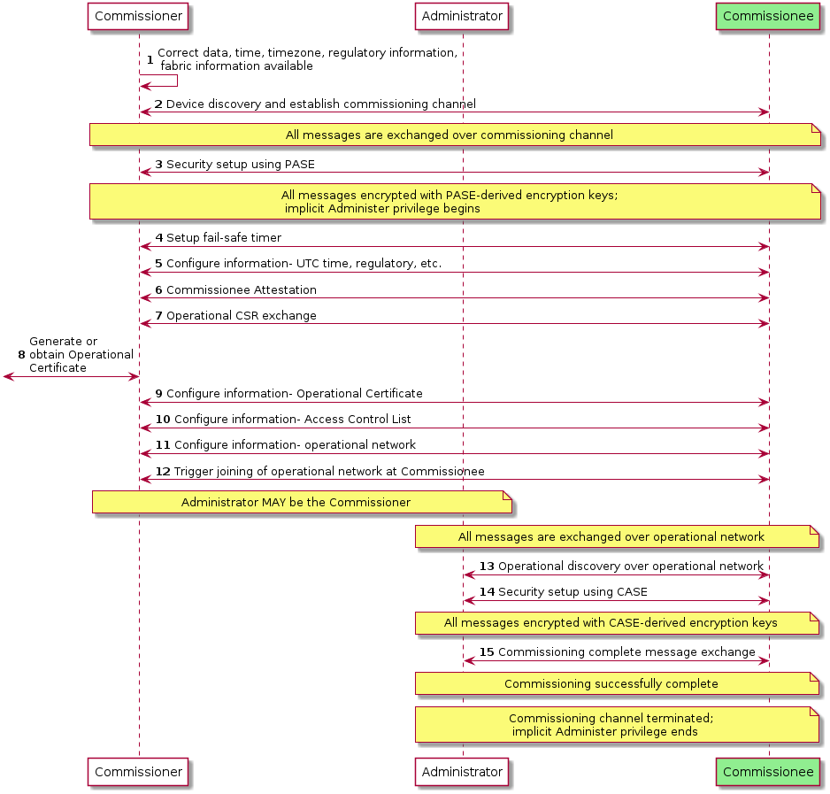
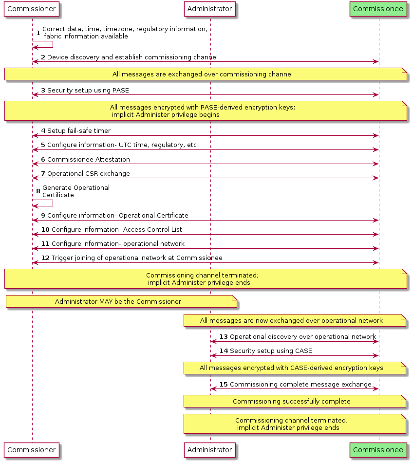
5.6. Administrator Assisted Commissioning Flows
5.6.1. Introduction
In this method, a current Administrator of a Node first sends the Open Commissioning Window command to the Node over a CASE session. The new Administrator MUST already have network connectivity and complete commissioning based on the two flows described below.
The commands for these flows are defined in Section 11.18, “Administrator Commissioning Cluster”.
5.6.2. Basic Commissioning Method (BCM)
This method is OPTIONAL for Nodes and Administrators/Commissioners to implement. In this method, the current Administrator MUST send the Open Basic Commissioning Window command to the Node over a CASE session. The Node SHALL advertise its presence over DNS-SD (see Section 5.4.2.7, “Using Existing IP-bearing Network” and Commissionable Node Discovery) after receiving the Open Basic Commissioning Window command.
The new Administrator’s Commissioner then completes commissioning with the Node using similar Commissioning flow as it would do for a factory-new device (although note that IP channel is used for discovery). It can either scan the QR code format or use the Manual Pairing Code format of the Section 5.1, “Onboarding Payload” of the Node.
The following steps describe a possible sequence of events for BCM commissioning:
-
Current Administrator puts the Node in Open Basic Commissioning Window for a specified time window, and receives success response from the Node on the Open Basic Commissioning Window command.
-
When the targeted Node is a SED, the current Administrator can guide the user to perform some action to 'wake' the device from its sleep cycle.
-
-
New Administrator completes commissioning within the prescribed window using steps outlined in Figure 30, “Concurrent connection commissioning flow”.
5.6.3. Enhanced Commissioning Method (ECM)
This method is MANDATORY for Nodes and Commissioners/Administrators to implement.
When using ECM, the Node’s current Administrator instructs the Node over a CASE session, to go into Open Commissioning Window.
It SHALL choose a new RANDOM passcode and SHALL compute and send the corresponding PAKE passcode verifier to the Node. Actual value of the passcode SHALL NOT be sent to the Node.
The current Administrator then presents the new passcode and discriminator as described below. The Node SHALL advertise its presence over DNS-SD (see Section 5.4.2.7, “Using Existing IP-bearing Network” and Commissionable Node Discovery) after receiving the Open Commissioning Window command.
Sleepy Nodes SHOULD include the optional SII key in their TXT advertisement.
5.6.3.1. Presentation of Onboarding Payload for ECM
Presentation of the passcode and other relevant information SHALL be done at least with one or more of the methods below, depending on the capabilities of the first Administrator opening the OCW:
-
If a user interface display is supported, the temporary Onboarding Payload SHALL be displayed using a textual representation of the Manual Pairing Code, using the 11-digit variant: it SHALL NOT contain the
VENDOR_IDorPRODUCT_IDas the onboarding of the node(s) using the ECM cannot be subject to User-Intent or Custom Flows. -
If a user interface display is supported, the temporary Onboarding Payload SHOULD also be displayed using the definitions included in Section 5.1.3, “QR Code” subject to the following constraints:
-
If only a single Node is being subjected to the ECM, the Vendor ID and Product ID in the onboarding payload SHALL be the same as those of that Node.
-
If multiple Nodes are being subjected to the ECM using the same onboarding payload, the Vendor ID SHALL be set to
0x0000(Matter Standard) and the Product ID SHALL be set to0x0000(consistent with the value used for not advertising a Product ID in Device Announcement) . -
The
Custom Flowelement SHALL be set to0to indicate standard flow. -
The
Discovery Capabilities MaskSHALL have ONLY bit 2 set to indicate the Node is only discoverable on the IP network. -
The
Passcodeelement SHALL be set by the existing Administrator to the same value as the passcode chosen for this ECM operation. -
The
Discriminatorelement SHALL be set by the existing Administrator to the same value as theDiscriminatorparameter in Section 11.18.8.1, “OpenCommissioningWindow (OCW) Command”. -
If multiple Nodes are subjected to ECM, the Section 5.1.5, “TLV Content” SHALL contain an entry with
kTag_NumberofDevicescontaining the number of devices that are expected to participate in the onboarding with this ECM operation. -
When the Commissioning Timeout parameter of the OCW command is set to less than the allowed maximum (15 minutes), the Section 5.1.5, “TLV Content” SHALL contain an entry with
kTag_CommissioningTimeoutcontaining the value of the Commissioning Timeout parameter used for this ECM operation.
-
-
If only audio output is supported, the temporary Onboarding Payload SHALL be delivered using a voice prompt of the Manual Pairing Code format. A method SHOULD be available for the user to have the pairing code repeated.
Remote UIs, both visual and audio — such as a manufacturer-specific mobile app or a web UI — are expressly permitted in the set of acceptable mechanisms for conveyance of the onboarding information.
This method allows a current Administrator to set multiple Nodes for commissioning with a new administrator with an appropriate Commissioning Window, by turning on Open Commissioning Window and sending the PAKE passcode verifier to a series of Nodes. The new Administrator uses the information in Manual Pairing Code to discover the Nodes that are in Commissioning mode and commission them using the new passcode.
The following steps describe a possible sequence of events for ECM commissioning:
-
Current Administrator puts the Node(s) in commissioning mode for a specified time window with a new setup passcode, and receives success responses from the involved Node(s) on the Open Commissioning Window command.
-
When one or more SED are among the targeted Nodes, the current Administrator can guide the user to perform some action to 'wake' these devices from their sleep cycle.
-
-
Current Administrator presents Onboarding Payload as described above.
-
New Administrator completes commissioning within the prescribed window using steps outlined in Figure 30, “Concurrent connection commissioning flow”.
5.6.4. Open Commissioning Window
The following sequence diagram shows steps current Administrator takes to enable Open Commissioning Window.
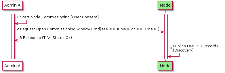
5.7. Device Commissioning Flows
This section describes the three different flows for out-of-box commissioning that a Matter device manufacturer may select for a given product. For each flow, a description is provided which includes actions required to place the device into commissioning mode, fields in the Onboarding Payload which identify the flow selected by the device manufacturer, fields in the Distributed Compliance Ledger that provide information used for commissioning and help the Commissioner provide the user with appropriate instructions, and requirements for device packaging relating to the Onboarding Payload. The three flows are the following:
-
Standard Commissioning Flow
-
User-Intent Commissioning Flow
-
Custom Commissioning Flow
Matter device manufacturers SHALL use the Distributed Compliance Ledger to provide commissioners with information and instructions for both initial and secondary commissioning, and SHOULD use this Ledger to provide links to the user guide, a link to a manufacturer app, and other pre-setup information, to enable an optimal commissioning flow without requiring bilateral arrangements between each commissioner manufacturer and each device manufacturer.
Some fields in the Ledger SHALL or SHOULD be populated, depending on the type of commissioning flow, as detailed in the text below and in the Distributed Compliance Ledger section.
5.7.1. Standard Commissioning Flow
-
A Standard Commissioning Flow device SHALL be available for initial commissioning by any Matter commissioner.
-
A Standard Commissioning Flow device, when in factory-new state, SHALL start advertising automatically upon power on (see Commencement).
-
A Standard Commissioning Flow device SHALL set Custom Flow bits in the Onboarding Payload to indicate '0 - Standard Flow'.
-
A Standard Commissioning Flow device SHALL follow the rules for Manual Pairing Code and QR Code Inclusion.
-
For the case where the device has stopped advertising (e.g. user has powered on the device longer ago than the advertisement period), the manufacturer SHOULD provide guidance about how to bring the device back into advertising mode using the CommissioningModeInitialStepsHint field from the Distributed Compliance Ledger. Commissioners SHOULD use this information to guide the user for this case.
-
When commissioning fails, the commissioner MAY also reference Distributed Compliance Ledger fields such as UserManualUrl, SupportUrl and ProductUrl to assist the user in further steps to resolve the issue(s).
-
The Distributed Compliance Ledger entries for Standard Commissioning Flow devices SHALL include the CommissioningCustomFlow field set to '0 - Standard' and the CommissioningModeInitialStepsHint field set to a non-zero integer value, with bit 0 (Power Cycle) being set to 1. The CommissioningModeInitialStepsInstruction field SHALL be set when CommissioningModeInitialStepsHint has a Pairing Instruction dependency.
| Field Name | Value(s) |
|---|---|
CommissioningCustomFlow |
0 - Standard (Mandatory) |
CommissioningModeInitialStepsHint |
This field SHALL be set to a non-zero integer value. See Pairing Hint Table for a complete list of pairing instructions. Example value: 33 - The following bits are set: 0 (Power Cycle - Mandatory), 5 (Device Manual - Optional). Bit 1 (Device Manufacturer URL) MAY be set. |
CommissioningModeInitialStepsInstruction |
The field SHALL be set when CommissioningModeInitialStepsHint has a Pairing Instruction dependency. See PI Dependency column of Pairing Hint Table to determine which pairing hints have Pairing Instruction dependency and therefore require this field to be populated. |
5.7.2. User-Intent Commissioning Flow
-
A User-Intent Commissioning Flow device SHALL be available for initial commissioning by any Matter commissioner.
-
A User-Intent Commissioning Flow device, when in factory-new state, SHALL NOT start advertising automatically upon application of power (see Commencement).
-
To place a User-Intent Commissioning Flow device into advertising mode, some form of user interaction with the device beyond application of power is required (see Pairing Hint Table). If a Device Manufacturer setup artifact is required for this, beyond documentation, then the device is a Custom Commissioning Flow device and not a User-Intent Commissioning Flow device. The documentation MAY be printed or in the form of online documentation (e.g. Section 11.22.5.8, “UserManualUrl”).
-
A User-Intent Commissioning Flow device SHALL follow the rules for Manual Pairing Code and QR Code Inclusion.
-
The Distributed Compliance Ledger entries for User-Intent Commissioning Flow devices SHALL include the CommissioningCustomFlow field set to '1 - User Intent' and the CommissioningModeInitialStepsHint field set to a non-zero integer value. Bit 0 (Power Cycle) in the CommissioningModeInitialStepsHint field SHALL be set to 0. The CommissioningModeInitialStepsInstruction field SHALL be set when CommissioningModeInitialStepsHint has a Pairing Instruction dependency.
-
A User-Intent Commissioning Flow device SHALL set Custom Flow bits in the Onboarding Payload to indicate '1 - User Intent'.
-
The commissioner SHOULD reference Distributed Compliance Ledger fields such as CommissioningModeInitialStepsHint, CommissioningModeInitialStepsInstruction, UserManualUrl, and SupportUrl to assist the user during commissioning, e.g. to explain how to bring the device into commissioning mode.
| Field Name | Value(s) |
|---|---|
CommissioningCustomFlow |
1 - User Intent (Mandatory) |
CommissioningModeInitialStepsHint |
This field SHALL be set to a non-zero integer value. See Pairing Hint Table for a complete list of pairing instructions. Example value: 96 - The following bits are set: 6 (Press Reset Button - Optional), 5 (Device Manual - Optional). Bit 1 (Device Manufacturer URL) MAY be set. |
CommissioningModeInitialStepsInstruction |
The field SHALL be set when CommissioningModeInitialStepsHint has a Pairing Instruction dependency. See PI Dependency column of Pairing Hint Table to determine which pairing hints have Pairing Instruction dependency and therefore require this field to be populated. |
5.7.3. Custom Commissioning Flow
-
A Custom Commissioning Flow device SHALL require interaction with custom steps, guided by a service provided by the manufacturer for initial device setup, before it can be commissioned by any Matter commissioner.
-
A Custom Commissioning Flow device MAY include the Onboarding Payload on-device or in packaging. If it is not included on the device or in packaging, then it SHALL be provided to the user through other means provided by the manufacturer.
-
A Custom Commissioning Flow device SHALL set Custom Flow bits in the Onboarding Payload to indicate '2 - Custom'.
-
The Distributed Compliance Ledger entries for Custom Commissioning Flow devices SHALL include:
-
the CommissioningCustomFlow field set to '2 - Custom'
-
the CommissioningModeInitialStepsHint with bit 0 (Power Cycle) set to 0 and bit 1 (Device Manufacturer URL) set to 1
-
the CommissioningCustomFlowUrl field populated in order to indicate to commissioners that initial commissioning can only be completed by the user visiting the URL contained therein.
This URL will typically lead to a web page with relevant instructions and/or to a server which (e.g. by looking at the User-Agent) redirects the user to allow viewing, downloading, installing or using a manufacturer-provided means for guiding the user through the process and bring the device into a state that it is available for commissioning by any commissioner.
Since the URL is retrieved from a DCL entry corresponding to a specific VID and PID combination, the device manufacturer MAY choose to use any constructed URL valid in a HTTP GET request (i.e. dedicated for the product the user wants to commission) such as, for example,https://www.example.com/download-install-app?vid=FFF1&pid=1234. All HTTP based URLs SHALL use thehttpsscheme.
-
-
When a Commissioner encounters a device with Custom Flow field (in Onboarding Payload) or its CommissioningCustomFlow field (in Distributed Compliance Ledger) set to '2 - Custom', it SHOULD use the CommissioningCustomFlowUrl to guide the user on how to proceed, unless it has alternative means to guide the user to successful commissioning.
-
If a Commissioner follows or launches the CommissioningCustomFlowUrl after a User request, it SHALL expand it as described in Section 5.7.3.1, “CommissioningCustomFlowUrl format”.
-
-
A manufacturer contemplating using this flow should realize that
-
This flow typically requires internet access to access the URL, so initial commissioning of the device may fail if there is no internet connection at that time/location.
-
If the flow requires an app, it needs to be made available for popular platforms amongst the user population; some of their platforms running a commissioner (e.g. a smart speaker not running a popular mobile OS) may thus not be able to be used for the initial commissioning of such devices.
-
| Field Name | Value(s) |
|---|---|
CommissioningCustomFlow |
2 - Custom (Mandatory) |
CommissioningCustomFlowUrl |
'URL' - Device Manufacturer URL (Mandatory) |
CommissioningModeInitialStepsHint |
This field SHALL be set to a non-zero integer value with at least bit 1 set (Device Manufacturer URL). See Pairing Hint Table for a complete list of pairing instructions. Example value: 2 - The following bits are set: 1 (Device Manufacturer URL) (Mandatory). |
CommissioningModeInitialStepsInstruction |
The field SHALL be set when CommissioningModeInitialStepsHint has a Pairing Instruction dependency. See PI Dependency column of Pairing Hint Table to determine which pairing hints have Pairing Instruction dependency and therefore require this field to be populated. |
5.7.3.1. CommissioningCustomFlowUrl format
The CommissioningCustomFlowUrl MAY contain a query component (see RFC 3986 section 3.4).
If a query is present, it SHALL be composed of one or more key-value pairs:
-
The query SHALL use the
&delimiter between key/value pairs. -
The key-value pairs shall in the format
name=<value>wherenameis the key name, and<value>is the contents of the value encoded with proper URL-encoded escaping. -
If key
MTcuis present, it SHALL have a value of "_" (i.e.MTcu=_). This is the "callback URL (CallbackUrl) placeholder". -
If key
MTopis present, it SHALL have a value of "_" (i.e.MTop=_). This is the "onboarding payload placeholder". -
Any key whose name begins with
MTnot mentioned in the previous bullets SHALL be reserved for future use by this specification. Manufacturers SHALL NOT include query keys starting withMTin either theCommissioningCustomFlowUrlorCallbackUrlunless they are referenced by a version of this specification.
When the CommissioningCustomFlowUrl for a Custom Commissioning Flow device includes the MTop key, the Passcode embedded in any Onboarding Payload placed on-device or in packaging SHALL NOT be one that can be used for secure channel establishment with the device. This requirement is intended to ensure a shared secret used for proof of possession will not be transferred to a server without user consent. A Custom Commissioning Flow device MAY utilize Onboarding Payload fields such as the Serial Number (see kTag_SerialNumber) to pass device identification to the server specified in CommissioningCustomFlowUrl, as these fields by themselves could not be used to gain access to the device on their own like the Passcode could.
When the CommissioningCustomFlowUrl for a Custom Commissioning Flow device includes the MTop key, the Passcode embedded in any Onboarding Payload placed on-device or in packaging MAY be set to 0 in order to provide a hint to the Commissioner that it is not one that can be used for secure channel establishment with the device. This would allow the Commissioner to avoid attempting to commission the device if an advertisement from it is detected.
Any other element in the CommissioningCustomFlowUrl query field not covered by the above rules, as well as the fragment field (if present), SHALL remain as obtained from the Distributed Compliance Ledger's CommissioningCustomFlowUrl field, including the order of query key/value pairs present.
5.7.3.1.1. Expansion of CommissioningCustomFlowUrl by Commissioner
Once the URL is obtained, it SHALL be expanded to form a final URL (ExpandedCommissioningCustomFlowUrl) by proceeding with the following substitution algorithm on the original CommissioningCustomFlowUrl:
-
If key
MTcuis present, compute theCallbackUrldesired (see Section 5.7.3.2, “CallbackUrl format for Custom Commissioning Flow response”), and substitute the placeholder value "_" (i.e. inMTcu=_) in theCommissioningCustomFlowUrlwith the desired contents, encoded with proper URL-encoded escaping (see RFC 3986 section 2). -
If key
MTopis present, substitute the the placeholder value "_" (i.e. inMTop=_) in theCommissioningCustomFlowUrlwith either numeric manual code, or QR code body including theMT:prefix and TLV data (if present), encoded with proper URL-encoded escaping (see RFC 3986 section 2). Note that both methods SHOULD be supported by the Manufacturer’s custom flow.
A Commissioner SHALL NOT append the MTop= query key/value pair unless the key/value pair was already present as MTop=_ in the CommissioningCustomFlowUrl previously obtained.
This constraint enables the determination of which products make use of the payload in their Custom Commissioning Flow infrastructure by inspection of the Distributed Compliance Ledger records.
The final URL after expansion (ExpandedCommissioningCustomFlowUrl) SHALL be the one to follow per Section 5.7.3, “Custom Commissioning Flow”, rather than the original value obtained from the Distributed Compliance Ledger.
5.7.3.2. CallbackUrl format for Custom Commissioning Flow response
If a CallbackUrl field (i.e. MTcu=) query field placeholder is present in the CommissioningCustomFlowUrl,
the Commissioner MAY replace the placeholder value "_" in the ExpandedCommissioningCustomFlowUrl
with a URL that the manufacturer custom flow can use to make a smooth return to the Commissioner when the device is in a state that it can be commissioned.
This URL field MAY contain a query component (see RFC 3986 section 3.4).
If a query is present, it SHALL be composed of one or more key-value pairs:
-
The query SHALL use the
&delimiter between key/value pairs. -
The key-value pairs SHALL follow the format
name=<value>wherenameis the key name, and<value>is the contents of the value encoded with proper URL-encoded escaping. -
If key
MTropis present, it SHALL have a value of "_" (i.e.MTrop=_). This is the placeholder for a "returned onboarding payload" provided by the manufacturer flow to the Commissioner. -
Any key whose name begins with
MTnot mentioned in the previous bullets SHALL be reserved for future use by this specification.
Any other element in the CallbackUrl query field not covered by the above rules, as well as the fragment field (if present), SHALL remain as provided by the Commissioner through embedding within the ExpandedCommissioningCustomFlowUrl, including the order of query key/value pairs present.
5.7.3.2.1. Expansion of CallbackUrl by the manufacturer custom flow
Once the CallbackUrl is obtained by the manufacturer flow, it MAY be expanded to form a final ExpandedCallbackUrl URL to be used by proceeding with the following substitution algorithm on the provided CallbackUrl:
-
If key
MTropis present, the manufacturer custom flow having received the initial query containing theCallbackUrlMAY compute an Onboarding Payload in QR code format includingMT:prefix, and substitute the placeholder value "_" (i.e. inMTrop=_) in theCallbackUrlwith the desired contents, encoded with proper URL-encoded escaping (see RFC 3986 section 2).-
The contents of the
MTrop=_key/value pair in theExpandedCallbackUrlSHALL only be expanded if the manufacturer custom flow, having received the initial query containing theCallbackUrl, supports opening a commissioning window on the target device and supports conveying the corresponding onboarding payload to the Commissioner. -
The return onboarding payload, if provided, SHALL contain an ephemeral
Passcodeand not a permanent code that can be used in a subsequent commissioning window. If the manufacturer wants thePasscodeembedded in the Onboarding Payload placed on-device or in packaging to be the one used for session establishment with the Commissioner, then the manufacturer SHALL NOT include theMTopkey in itsCommissioningCustomFlowUrland SHALL NOT populate theMTropvalue in theCallbackUrlexpansion. -
The contents of the return onboarding payload, if provided, SHALL be constructed to match the state of the device at the moment the
ExpandedCallbackUrlis opened. At least one ingredient which needs to be adapted relative to the received Onboarding Payload is theCustom Flowfield which needs to be0for the return onboarding payload. -
The presence of this field is to assist automatically resuming commissioning without additional data entry (QR code or numeric manual code) by the user at the Commissioner that initially triggered the custom flow. The manufacturer custom flow SHOULD provide an alternate means of conveying the onboarding payload, such as a manual pairing code.
-
Note that if the information in the initial onboarding payload that caused triggering of a Custom Commissioning Flow was directly usable, it may be used by the Commissioner, either upon being triggered through the
ExpandedCallbackUrlhaving been opened, or autonomously as a fallback. -
Commissioners providing a
CallbackUrlto the manufacturer custom flow through theExpandedCommissioningCustomFlowUrlSHOULD support using theExpandedCallbackUrlto trigger resumption of Commissioning flow if theExpandedCallbackUrlis followed, otherwise the Commissioner SHOULD NOT substitute theMTcuquery field when expanding theCommissioningCustomFlowUrlinto theExpandedCommissioningCustomFlowUrl. -
If the manufacturer custom flow failed to make the device commissionable, it SHALL NOT replace the placeholder value "_" of an included
MTrop=_key/value pair, to avoid a Commissioner attempting to discover or commission a device not made ready by the custom flow.
-
A manufacturer custom flow having received an ExpandedCommissioningCustomFlowUrl SHOULD attempt to open the ExpandedCallbackUrl, on completion of the steps, if an ExpandedCallbackUrl was computed from the CallbackUrl and opening such a URL is supported.
5.7.3.3. Examples of CommissioningCustomFlow URLs
Below are some examples of valid ExpandedCommissioningCustomFlowUrl for several valid values of CommissioningCustomFlowUrl, as well as some examples of invalid values of CommissioningCustomFlowUrl:
-
Valid URL with no query string:
-
Before expansion: https://company.example.com/matter/custom/flows/vFFF1p1234
-
After expansion: https://company.example.com/matter/custom/flows/vFFF1p1234 (no change)
-
-
Invalid URL with no query string:
httpscheme is not allowed: -
Valid URL with basic manufacturer-specific scheme for query:
-
Before expansion: https://company.example.com/matter/custom/flows?vid=FFF1&pid=1234
-
After expansion: https://company.example.com/matter/custom/flows?vid=FFF1&pid=1234 (no change)
-
-
Valid URL with
MTop=_placeholder using QR format onboarding payload embedding:-
Before expansion: https://company.example.com/matter/custom/flows?vid=FFF1&pid=1234&MTop=_
-
After expansion: https://company.example.com/matter/custom/flows?vid=FFF1&pid=1234&MTop=MT%3A-MOA57ZU02IT2L2BJ00
-
Onboarding payload QR content
MT:-MOA57ZU02IT2L2BJ00was embedded withinMTopkey
-
-
-
Valid URL with
MTop=_placeholder using numeric manual code onboarding payload embedding:-
Before expansion: https://company.example.com/matter/custom/flows?vid=FFF1&pid=1234&MTop=_
-
After expansion: https://company.example.com/matter/custom/flows?vid=FFF1&pid=1234&MTop=610403146665521046600
-
Onboarding numeric manual code
610403146665521046600was embedded withinMTopkey
-
-
-
Valid URL with
MTop=_placeholder using numeric manual code onboarding payload embedding, using a different order of keys/value pairs than the previous example:-
Before expansion: https://company.example.com/matter/custom/flows?pid=1234&MTop=_&vid=FFF1
-
After expansion: https://company.example.com/matter/custom/flows?pid=1234&MTop=610403146665521046600&vid=FFF1
-
Onboarding numeric manual code
610403146665521046600was embedded withinMTopkey
-
-
-
Valid URL with onboarding payload elided (because commissioner could not provide it):
-
Before expansion: https://company.example.com/matter/custom/flows?vid=FFF1&pid=1234&MTop=_
-
After expansion: https://company.example.com/matter/custom/flows?vid=FFF1&pid=1234&MTop=_ (no change)
-
-
Valid URL, return onboarding payload and
CallbackUrlrequested:-
Before expansion:
https://company.example.com/matter/custom/flows?vid=FFF1&pid=1234&MTop=_&MTcu=_
-
After expansion:
https://company.example.com/matter/custom/flows?vid=FFF1&pid=1234&MTop=MT%3A-MOA57ZU02IT2L2BJ00&MTcu=https%3A%2F%2Fcommissioner.example.com%2Fcb%3Ftoken%3DmAsJ6_vqbr-vjDiG_w%253D%253D%26MTrop%3D_
-
The
ExpandedCommissioningCustomFlowURL contains:-
An embedded onboarding payload QR content value of
MT:-MOA57ZU02IT2L2BJ00 -
A
CallbackUrlwith a Commissioner-provided arbitrarytoken=key/value pair and theMTrop=key/value pair place-holder to indicate support for a return onboarding payload: https://commissioner.example.com/cb?token=mAsJ6_vqbr-vjDiG_w%3D%3D&MTrop=_ -
After expansion of the
CallbackUrl(MTcukey) into anExpandedCallbackUrl, with an example return onboarding payload ofMT:-MOA5.GB00V68T62O10, theExpandedCallbackUrlwould be:https://commissioner.example.com/cb?token=mAsJ6_vqbr-vjDiG_w%3D%3D&MTrop=MT%3A-MOA5.GB00V68T62O10
Note that the
MTcukey/value pair was initially provided URL-encoded within theExpandedCommissioningCustomFlowURL and theMTrop=_key/value pair placeholder now contains a substituted returned onboarding payload.
-
-
-
Invalid URL, due to
MTza=79key/value pair in reservedMT-prefixed keys reserved for future use:
5.7.3.4. Example Custom Commissioning Flow
An example of this flow is illustrated below. The "DCL info" concept denotes that the Commissioner SHALL collect the information from the DCL via some mechanism, such as a network resource accessible to the Commissioner containing a replicated set of the DCL’s content.
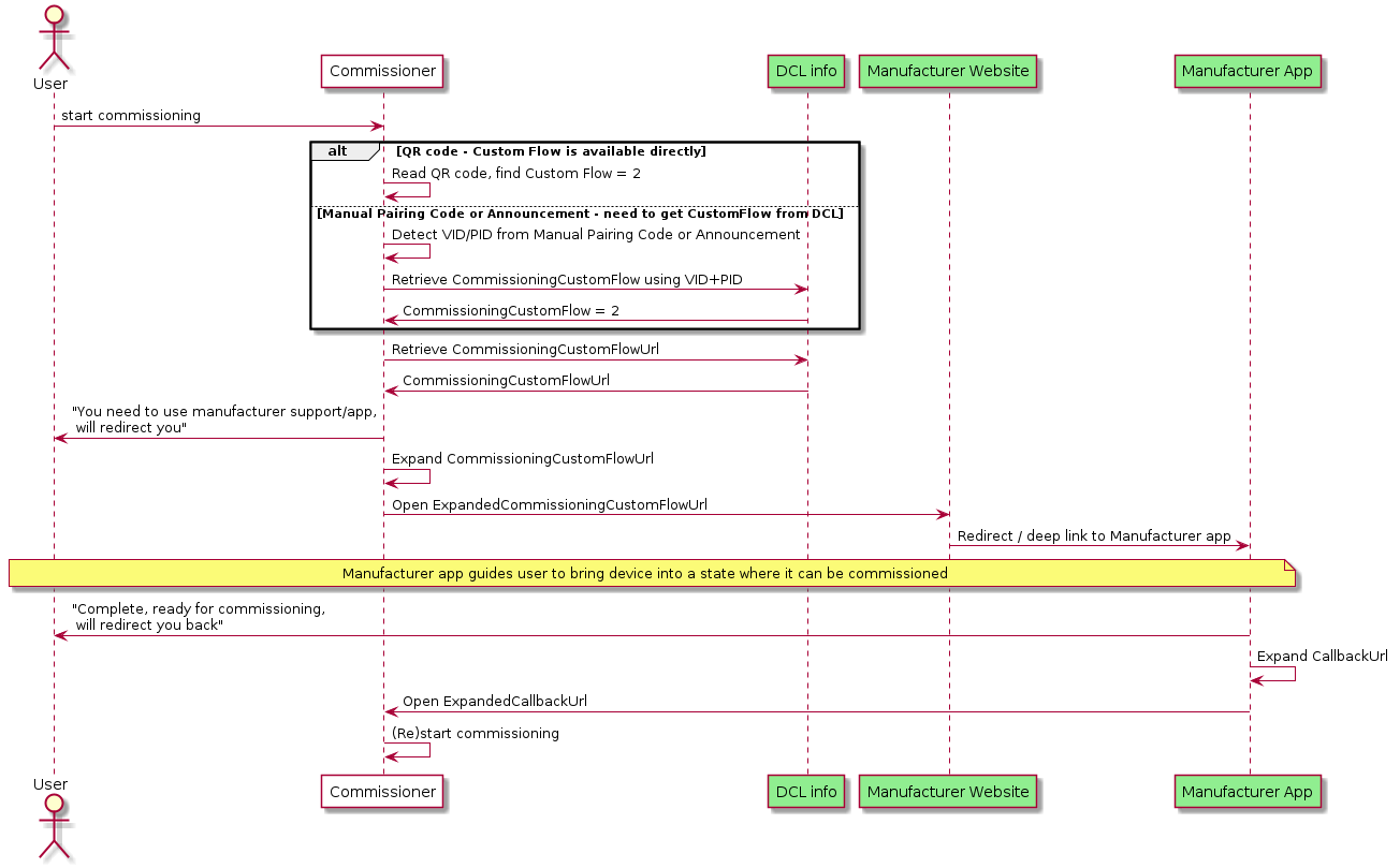
In the flow above:
-
In the final steps, the User has to perform the trigger to the first Commissioner, so that it can start or continue the commissioning process.
-
If possible, a Commissioner MAY continue to scan for announcements from the device in the background while any manufacturer-specific app is configuring the device to be available for commissioning. The Commissioner may need a new OnboardingPayload provided to the User by the Manufacturer Website or App.
-
In order to simplify the flow, the Commissioner MAY:
-
Include the onboarding payload obtained from the user (see
MTopkey in Section 5.7.3.1, “CommissioningCustomFlowUrl format”) within theCommissioningCustomFlowUrl. -
Include a callback URL (see
MTcukey in Section 5.7.3.1, “CommissioningCustomFlowUrl format”) within theExpandedCommissioningCustomFlowUrl.
-
-
The Manufacturer Website or App MAY utilize the
CallbackUrlfield, if provided in the query string, in order to simplify the process for signaling the completion of the manufacturer-specific part of the flow back to the Commissioner. When doing so, the Manufacturer Website or App SHOULD put the device into Commissioning mode and SHOULD provide the corresponding onboarding payload to the Commissioner using theMTropkey/value pair within the ExpandedCallbackUrl.
5.7.4. Manual Pairing Code and QR Code Inclusion
Manual Pairing Code and QR setup codes enable secure commissioning and provide a consistent experience that many users are familiar with. However, because they contain a symmetric security code it is not appropriate in all circumstances to have them be in a readily accessible location on the device, such as printed on the back.
The following are the requirements and recommendations regarding the QR Code and Manual Pairing code for Standard and User Intent Commissioning Flow Devices. Custom Commissioning Flow Device rules are described in the Custom Commissioning Flow.
The term 'on-device' allows for a physical label affixed to the device or printed directly on the device, as well as one that can be displayed on demand through some physical interface properties of the device (e.g. visual or audio).
-
Devices SHALL include the Manual Pairing code on-device or in packaging.
-
Devices SHALL NOT have the QR nor the manual pairing code in an unprotected format on the outer packaging.
-
Devices SHOULD include the QR Code, and SHOULD include it alongside the Manual Pairing Code on-device or in packaging.
-
Manual Pairing Code and QR Code on-device MAY be removable or obscured to allow the owner to prevent commissioning without their consent.
-
Devices MAY include the QR Code and Manual Pairing Code in multiple forms (see below).
Presentation of the QR Code and Manual Pairing code on-device can occur in many forms to allow for adherence to device security requirements and manufacturing considerations. For example security devices could limit the access to the QR code or Manual Pairing Code to avoid an unauthorized user obtaining the information by simple inspection, or make the QR code and/or Manual Pairing Code removable.
The following is a list of possible ways that are acceptable to satisfy the requirements of inclusion of the QR code and Manual Pairing Code. An entry in the list should not be interpreted as being mutually exclusive with another entry. A device SHOULD include as many of these ways as possible.
-
QR and Manual Pairing Code shown via an on-device display (when available)
-
QR and Manual Pairing Code printed on-device, with removal/obscuring considerations noted above.
-
Manual Pairing Code presented on-device via audio output (when available)
-
QR and Manual Pairing Code printed on in-packaging materials.
The following are examples of QR code and Manual Pairing Code inclusion.
-
QR Code and Manual Pairing Code printed on a Matter wireless shade inside the battery compartment cover, and provided in the packaging.
-
QR Code and Manual Pairing code on a Matter Smart Thermostat that can be activated via an on-device User Interface and displayed only on screen.
-
QR Code and Manual Pairing code for a security sensor that is provided in the packaging, and on-device hidden behind a tamper-monitored cover.
-
QR code provided on an E12 light bulb, with manual pairing code on a removable label (the area of QR code likely fits better on small form factor bulb than the area for a 13 character string).
-
A wearable device with only a Manual Pairing Code printed on the fabric. No QR code is present because of the difficulty in scanning a QR code on an irregular surface.
-
A Smart speaker, without printed QR or manual pairing code on the device (but possibly in-packaging), that can be triggered to read out a Manual Pairing Code.
5.8. In-field Upgrade to Matter
This (informative) section discusses the case of a pre-Matter device currently in the user’s home which gets software updated to support Matter, and which steps (either Matter-specified or manufacturer specific) would typically be applied to accomplish this goal.
-
The initial situation is a device which is connected to the local network, and some manufacturer specific means (e.g. a manufacturer-provided app) is used to provide new firmware (including Matter functionality) to the device, along with the associated Certification Declaration. Also, a unique Device Attestation Certificate is provided into the device using secure, manufacturer-specific means.
-
The device restarts to enable the new firmware, and is now an uncommissioned Matter device.
-
The device can be commissioned by any Commissioner; the Onboarding Payload needs to be provided to that Commissioner (since this information is not provided on or with the device out of the factory).
-
For this, similar mechanisms as discussed as in Section 5.6.3, “Enhanced Commissioning Method (ECM)” can be employed:
-
information equivalent to the parameters of the Open Commissioning Window command is sent to the device using some secure manufacturer-defined means
-
presentation of the passcode and other relevant information can be performed using the mechanisms described in Section 5.6.3.1, “Presentation of Onboarding Payload for ECM”.
-
-
For devices with a means to output the Onboarding Payload themselves (e.g. device with a display or audio output), alternatively, similar mechanisms as discussed as in Section 5.6.2, “Basic Commissioning Method (BCM)” can be employed:
-
information equivalent to the parameters of the Open Basic Commissioning Window command is sent to the device using some secure manufacturer-defined means
-
the device itself presents Onboarding Payload.
-
-
6. Device Attestation and Operational Credentials
This chapter describes the procedures and cryptographic credentials involved in establishing trust between entities.
The Device Attestation section provides mechanisms for Commissioners and Administrators to determine whether a Node is a genuine certified product before sharing sensitive information such as keys and other credentials. The Device Attestation feature relies on a Device Attestation Certificate (DAC) chain and on a Certification Declaration (CD).
The Node Operational Credentials section describes the credentials used by all Nodes to mutually authenticate each other during Certificate-Authenticated Session Establishment, including the Node Operational Certificate (NOC) chain. These credentials form the basis of how Nodes are identified and take part in securing operational unicast communication.
6.1. Common Conventions
This chapter makes use of digital certificates in several subsections. All certificates within this specification are based on X.509v3-compliant certificates as defined in RFC 5280. The storage format of the certificates depends on application (e.g., DAC or NOC chain), but all certificates are directly compatible with X.509v3 DER representation after suitable loading or decompression.
In order to simplify further exposition, this subsection contains some common normative conventions that SHALL apply to all digital certificates described in this specification.
The following certificate formats are defined within this specification:
-
Compressed Node Operational credentials certificate chain elements in Matter Operational Certificate Encoding or "Matter Certificate" format:
-
Device Attestation certificate chain elements in Standard X.509 DER format:
-
Device Attestation Certificate (DAC): see Section 6.2.2.3, “Device Attestation Certificate (DAC)”
-
Product Attestation Intermediate (PAI): see Section 6.2.2.4, “Product Attestation Intermediate (PAI) Certificate”
-
Product Attestation Authority (PAA): see Section 6.2.2.5, “Product Attestation Authority (PAA) Certificate”
-
6.1.1. Encoding of Matter-specific RDNs
In addition to the standard DN (Distinguished Names) attribute types that appear in certificate Subject and Issuer fields, there are Matter-specific DN attribute types under the 1.3.6.1.4.1.1.37244 private arc. These are listed in Table 54, “Matter-specific DN Object Identifiers”. These OID values are assigned by the Connectivity Standards Alliance for use with Matter. All of these Matter-specific RDNs encode values normatively defined as scalars.
When used in Matter Operational Certificate (TLV) format (see Section 6.5, “Operational Certificate Encoding”), Matter-specific DN attribute types SHALL be encoded in Matter TLV as unsigned integers with the specified length.
When used in X.509 ASN.1 DER format certificate encoding, Matter-specific DN attribute types SHALL have their value encoded as either a UTF8String or PrintableString according to the table below. The values SHALL be encoded in network byte order as exactly twice their specified maximum octet length, encoded as uppercase hexadecimal number format without any separators or prefix, and without omitting any leading zeroes.
For example:
-
A scalar value
0x0123_4567_89AB_CDEFformatter-node-id:-
Scalar maximal length: 8 octets (64 bits)
-
Resulting string: "0123456789ABCDEF" (without quotes)
-
Resulting length: 16 characters
-
-
A scalar value
0xAA_33CCformatter-noc-cat:-
Scalar maximal length: 4 octets (32 bits)
-
Resulting string: "00AA33CC" (without quotes)
-
Resulting length: 8 characters
-
| TLV Tag | Matter name | Length (octets) | String length | ASN.1 OID | Types Allowed in X.509 |
|---|---|---|---|---|---|
17 |
|
8 |
16 |
UTF8String |
|
18 |
|
8 |
16 |
UTF8String |
|
19 |
|
8 |
16 |
UTF8String |
|
20 |
|
8 |
16 |
UTF8String |
|
21 |
|
8 |
16 |
UTF8String |
|
22 |
|
4 |
8 |
UTF8String |
|
N/A |
|
2 |
4 |
UTF8String, PrintableString |
|
N/A |
|
2 |
4 |
UTF8String, PrintableString |
6.1.2. Key Identifier Extension Constraints
Whenever an X.509 certificate contains Authority Key Identifier or Subject Key Identifier extensions, the associated Key Identifier SHALL be of a length of 20 octets, consistent with the length of derivation method (1) described in section 4.2.1.2 of [RFC 5280].
Further constraints related to the exact derivation appear in the following subsections:
-
Matter Certificates (NOC, ICAC, RCAC) Subject Key Identifier extension: see Section 6.5.11.4, “Subject Key Identifier Extension”
-
Matter Certificates Authority Key Identifier extension: see Section 6.5.11.5, “Authority Key Identifier Extension”
-
Device Attestation Certificate (DAC) extensions: see Section 6.2.2.3, “Device Attestation Certificate (DAC)”
-
Product Attestation Intermediate (PAI) Certificate extensions: see Section 6.2.2.4, “Product Attestation Intermediate (PAI) Certificate”
-
Product Attestation Authority (PAA) Certificate extensions: see Section 6.2.2.5, “Product Attestation Authority (PAA) Certificate”
6.1.3. Certificate Sizes
All certificates SHALL NOT be longer than 600 bytes in their uncompressed DER format. This constraints SHALL apply to the entire DAC chain (DAC, PAI, PAA) and NOC chain (NOC, ICAC, RCAC).
Wherever Matter Operational Certificate Encoding representation is used, all certificates SHALL NOT be longer than 400 bytes in their TLV form. This constraint only applies to the NOC chain (NOC, ICAC, RCAC) since the DAC chain (DAC, PAI, PAA) only appears in DER format.
All certificates used within Matter SHOULD be as short as possible.
6.1.4. Presentation of example certificates
Certificate bodies are presented for exemplary purposes in multiple formats within this chapter. Since the translation of an X.509 certificate from ASN.1 DER format to human-readable text format may lose fidelity, especially with regards to equivalent types (e.g., PrintableString versus IA5String versus UTF8String) or serialization when non-standard OIDs are seen, textual examples SHALL NOT be considered to be normative. Only direct encoding of DER encoding, such as PEM blocks, should be used to further study the examples. In case of unforeseen divergence between an example certificate illustration and the normative rules expressed in prose, the normative prose SHALL take precedence over an ambiguous interpretation of an example.
6.2. Device Attestation
6.2.1. Introduction
Certification of a Device includes configuring the Device with immutable credentials that can be cryptographically verified. Device Attestation is the step of the Commissioning process whereby a Commissioner cryptographically verifies a Commissionee is in fact a certified Device. This chapter describes the Device Attestation Certificate (DAC) and the systems involved in the verification of a DAC.
The processes used to convey the DAC from a Commissionee to a Commissioner, how to verify that a Commissionee holds the private key corresponding to its DAC, and specifically how the DAC is verified are described in Section 6.2.3, “Device Attestation Procedure”.
This chapter refers to the signature algorithm ECDSA with SHA256 and to the elliptic curve secp256r1 (aka prime256v1 and NIST P-256) in compliance with the mapping for version 1.0 of the Matter Message Format of the cryptographic primitives as specified in Chapter 3, Cryptographic Primitives. Future versions of this specification might adapt these references accordingly.
6.2.2. Device Attestation Certificate (DAC)
All commissionable Matter Nodes SHALL include a Device Attestation Certificate (DAC) and corresponding private key, unique to that Device. The DAC is used in the Device Attestation process, as part of Commissioning a Commissionee into a Fabric. The DAC SHALL be a DER-encoded X.509v3-compliant certificate as defined in RFC 5280 and SHALL be issued by a Product Attestation Intermediate (PAI) that chains directly to an approved Product Attestation Authority (PAA), and therefore SHALL have a certification path length of 2.
The DAC also SHALL contain specific values of Vendor ID and Product ID (see Section 6.2.2.2, “Encoding of Vendor ID and Product ID in subject and issuer fields”) in its subject field to indicate the Vendor ID and Product ID provenance of the attestation certificate.
See Section 6.2.3.1, “Attestation Information Validation” for how these are used.
The validity period of a DAC is determined by the vendor and MAY be set to the maximum allowed value of 99991231235959Z GeneralizedTime to indicate that the DAC has no well-defined expiration date.
The notation used in this section to describe the specifics of the DAC uses the ASN.1 basic notation as defined in X.680. The notation below also leverages types defined in RFC 5280 such as AlgorithmIdentifier, RelativeDistinguishedName, Validity, Time, UTCTime, GeneralizedTime, or permitted extension types. Additionally, the notation below uses the ASN.1 definitions captured in the figure below:
-- Matter signatures are ECDSA with SHA256
MatterSignatureIdentifier ::= SEQUENCE {
algorithm OBJECT IDENTIFIER(id-x962-ecdsa-with-sha256) }
-- Matter Names
-- The second to last RelativeDistinguishedName object in MatterDACName SEQUENCE SHALL contain an
-- attribute with type equal to matter-oid-vid and the last RelativeDistinguishedName object in the
-- SEQUENCE SHALL contain an attribute with type field set to matter-oid-pid
MatterDACName ::= SEQUENCE OF RelativeDistinguishedName
-- There are two acceptable formats for MatterPA name. The first is identical to MatterDACName,
-- i.e. the second to last RelativeDistinguishedName object in MatterPAName SEQUENCE SHALL contain an
-- attribute with type equal to matter-oid-vid and the last RelativeDistinguishedName object in the
-- SEQUENCE SHALL contain an attribute with type field set to matter-oid-pid. In the second acceptable
-- format, the last element of the MatterPAName SEQUENCE SHALL be an RelativeDistinguishedName with
-- an attribute with type field set to matter-oid-vid
MatterPAName ::= SEQUENCE OF RelativeDistinguishedName
-- Object definitions and references
-- X962 OIDs
id-x962 OBJECT IDENTIFIER ::= { iso(1) member-body(2) us(840) ansi-x962(10045) }
id-x962-ecdsa-with-sha256 OBJECT IDENTIFIER ::= { id-x962 signatures(4) ecdsa-with-SHA2(3) ecdsa-with-SHA256(2) }
id-x962-prime256v1 OBJECT IDENTIFIER ::= { id-x962 curves(3) prime(1) prime256v1(7) }
-- CSA and Matter specific OIDs
csa-root OBJECT IDENTIFIER ::= { iso(1) identified-organization(3) dod(6) internet(1) private(4) enterprise(1) zigbee(37244) }
-- root arc for attestation certificates
matter-att-root OBJECT IDENTIFIER ::= { csa-root 2 }
-- Matter Device Attestation Certificate DN attribute for the Vendor ID (VID)
matter-oid-vid OBJECT IDENTIFIER ::= { matter-att-root 1 }
-- Matter Device Attestation Certificate DN attribute for the Product ID (PID)
matter-oid-pid OBJECT IDENTIFIER ::= { matter-att-root 2 }
6.2.2.1. Device Attestation Public Key Infrastructure (PKI)
The Device Attestation PKI hierarchy consists of the PAA, PAI and individual DAC. The public key from the associated PAI certificate is used to cryptographically verify the DAC signature. The PAI certificate in turn is signed and attested to by the Product Attestation Authority (PAA) CA. The public key from the associated PAA certificate is used to cryptographically verify the PAI certificate signature. The PAA certificate is an implicitly trusted self-signed root certificate. In this way, the DAC chains up to the PAI certificate, which in turn chains up to the PAA root certificate. A PAI SHALL be assigned to a Vendor ID value. A PAI MAY further be scoped to a single ProductID value. If a PAI is used for multiple products, then it cannot be scoped to a ProductID value, otherwise the Device Attestation Procedure will fail policy validations.
Commissioners SHALL use PAA and PAI certificates to verify the authenticity of a Commissionee before proceeding with the rest of the Commissioning flow.
The subject of all DAC and PAI certificates SHALL be unique among all those issued by their issuer, as intended by RFC 5280 section 4.1.2.6, through the use of RelativeDistinguishedName s that ensure the uniqueness, such as for example a unique combination of commonName (OID 2.5.4.3), serialNumber (OID 2.5.4.5), organizationalUnitName (OID 2.5.4.11), etc. The exact additional constraints, including for the subject field, for PAA, PAI and DAC certificates, are presented in the following subsections.
The following figure shows the Device Attestation PKI hierarchy.
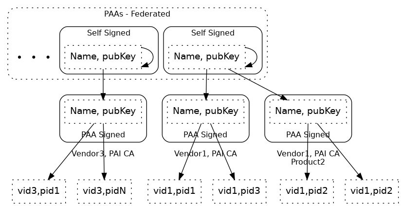
6.2.2.2. Encoding of Vendor ID and Product ID in subject and issuer fields
The values for VendorID and ProductID, where possible or required in issuer or subject fields SHALL be encoded by only one of two methods, without mixing the methods within a given field:
-
The "preferred method", using Matter-specific
RelativeDistinguishedNameattributes:-
VendorID encoded as
AttributeTypeAndValueentry withtypeequal to 1.3.6.1.4.1.37244.2.1, and value respecting encoding specified in Section 6.1.1, “Encoding of Matter-specific RDNs”. -
ProductID encoded as
AttributeTypeAndValueentry withtypeequal to 1.3.6.1.4.1.37244.2.2, and value respecting encoding specified in Section 6.1.1, “Encoding of Matter-specific RDNs”.
-
-
A "fallback method" to support certificate authorities that only allow customary RFC 5280 OIDs in the arc
{joint-iso-itu-t(2) ds(5) attributeType(4)}fortypevalues inAttributeTypeAndValueentries ofRelativeDistinguishedNameelements is to encode them as substrings within thecommonNameattribute type ({joint-iso-itu-t(2) ds(5) attributeType(4) commonName(3)}):-
VendorID value encoded with substring
Mvid:followed by exactly 4 uppercase hexadecimal characters without elision of leading zeroes, anywhere within thecommonName, such as for example:-
VendorID 0xFFF1 (65521 decimal):
Mvid:FFF1 -
VendorID 0x2A (42 decimal):
Mvid:002A
-
-
ProductID value encoded with substring
Mpid:followed by exactly 4 uppercase hexadecimal characters without elision of leading zeroes, anywhere within thecommonName, such as for example:-
ProductID 0xC20A (49674 decimal):
Mpid:C20A -
ProductID 0x3A5 (933 decimal):
Mpid:03A5
-
-
The "preferred method" leaves more space for content in the commonName attribute type if present. It is also less ambiguous which may allow simpler processing of certificate issuance policy validations in CAs that support the Matter-specific RelativeDistinguishedName attributes, and simplify the audit of certificates where Vendor ID and Product ID appear.
The "fallback method" is present to support less flexible CA infrastructure.
Fallback method to encode VendorID and ProductID
The "fallback method" requires exactly 9 characters that are safe to use in both PrintableString and UTF8String for either VendorID or ProductID encoding.
Since these VendorID and ProductID substrings have unambiguous format, they MAY be provided anywhere within a commonName value, and therefore separator selection does not need to be considered.
Note that the standard RFC 5280 length limitation for commonName attribute value is 64 characters in total (see ub-common-name in RFC 5280).
Using the "fallback method" for embedding of VendorID and ProductID in commonName in the subject field of a Device Attestation Certificate claiming VendorID 0xFFF1 and ProductID 0x00B1 can be illustrated with the following valid and invalid examples (without the double quotes):
-
"ACME Matter Devel DAC 5CDA9899 Mvid:FFF1 Mpid:00B1": valid and recommended since easily human-readable -
"ACME Matter Devel DAC 5CDA9899 Mpid:00B1 Mvid:FFF1": valid and recommended since easily human-readable -
"Mpid:00B1,ACME Matter Devel DAC 5CDA9899,Mvid:FFF1": valid example showing that order or separators are not considered at all for the overall validity of the embedded fields -
"ACME Matter Devel DAC 5CDA9899 Mvid:FFF1Mpid:00B1": valid, but less readable -
"Mvid:FFF1ACME Matter Devel DAC 5CDAMpid:00B19899": valid, but highly discouraged, since embedding of substrings within other substrings may be confusing to human readers. -
"ACME Matter Devel DAC 5CDA9899 Mvid:FF1 Mpid:00B1": invalid, since substring followingMvid:is not exactly 4 uppercase hexadecimal digits -
"ACME Matter Devel DAC 5CDA9899 Mvid:fff1 Mpid:00B1": invalid, since substring followingMvid:is not exactly 4 uppercase hexadecimal digits -
"ACME Matter Devel DAC 5CDA9899 Mvid:FFF1 Mpid:B1": invalid, since substring followingMpid:is not exactly 4 uppercase hexadecimal digits -
"ACME Matter Devel DAC 5CDA9899 Mpid: Mvid:FFF1": invalid, since substring followingMpid:is not exactly 4 uppercase hexadecimal digits
If either the Vendor ID (1.3.6.1.4.1.37244.2.1) or Product ID (1.3.6.1.4.1.37244.2.2) Matter-specific OIDs appear in any RelativeDistinguishedName in the subject or issuer fields of a certificate which is part of the Device Attestation Certificate chain path, then that certificate within the chain SHALL NOT have its commonName, if present, parsed for the "fallback method", in the rest of the issuer or subject field where the Matter-specific OIDs appear.
In other words, considering a field such as subject or issuer, the presence of either of these OIDs as the type for any AttributeTypeAndValue within any RelativeDistinguishedName of that field SHALL cause the "fallback method" to be skipped altogether for that field.
Otherwise, when the "fallback method" can legally be used, it SHALL only be used against AttributeTypeAndValue sequences where the type field is commonName ({joint-iso-itu-t(2) ds(5) attributeType(4) commonName(3)}) in the issuer and subject fields, and any mention thereafter of using or matching a "Vendor ID" or "Product ID" with regards to a Device Attestation Procedure step SHALL rely on values obtained with that method.
For example, if a given Product Attestation Intermediate certificate has a subject field employing a particular method of encoding the VendorID and ProductID, either using only Matter-specific OIDs or only the fallback method, then it follows that a Device Attestation Certificates issued by the certificate authority of that Product Attestation Intermediate SHALL have the same DistinguishedName content in its issuer field, so that the basic path validation algorithm works. That Device Attestation Certificate MAY however have the "fallback method" used within its subject field, if the Product Attestation Intermediate certificate authority is unable to encode/reflect the Matter-specific OIDs in RelativeDistinguishedName attributes within the subject field. The rules for whether to consider the canonical or "fallback method" for VendorID and ProductID encoding applies field by field independently for each instance of subject or issuer field found in certificates within the DAC chain.
6.2.2.3. Device Attestation Certificate (DAC)
The attributes in a DAC include:
Certificate ::= SEQUENCE {
tbsCertificate DACTBSCertificate,
signatureAlgorithm AlgorithmIdentifier,
signatureValue BIT STRING }
DACTBSCertificate ::= SEQUENCE {
version INTEGER ( v3(2) ),
serialNumber INTEGER,
signature MatterSignatureIdentifier,
issuer MatterPAName,
validity Validity,
subject MatterDACName,
subjectPublicKeyInfo SEQUENCE {
algorithm OBJECT IDENTIFIER(id-x962-prime256v1),
subjectPublicKey BIT STRING },
extensions DACExtensions }
DACExtensions ::= SEQUENCE {
basicConstraint Extension({extnID id-ce-basicConstraints, critical TRUE, extnValue BasicConstraints {cA FALSE} }),
keyUsage Extension({extnID id-ce-keyUsage, critical TRUE, extnValue KeyUsage({digitalSignature})}),
authorityKeyIdentifier Extension({extnID id-ce-authorityKeyIdentifier}),
subjectKeyIdentifier Extension({extnID id-ce-subjectKeyIdentifier}),
extendedKeyUsage Extension({extnID id-ce-extKeyUsage}) OPTIONAL,
authorityInformationAccess Extension({extnID id-pe-authorityInfoAccess}) OPTIONAL,
subjectAlternateName Extension({extnID id-ce-subjectAltName}) OPTIONAL
}
The DAC certificate SHALL follow the following constraints layered on
top of the encoding specified by RFC 5280 within the
TBSCertificate structure:
-
The
versionfield SHALL be set to2to indicate v3 certificate. -
The
signaturefield SHALL contain the identifier for signatureAlgorithmecdsa-with-SHA256. -
The
issuerfield SHALL be a sequence ofRelativeDistinguishedNames. -
The
issuerfield SHALL have exactly one VendorID value present. -
The
issuerfield SHALL have exactly zero or one ProductID value present. -
The
subjectfield SHALL be a sequence ofRelativeDistinguishedNames. -
The
subjectfield SHALL have exactly one VendorID value present.-
The VendorID value present in the
issuerfield SHALL match the VendorID value found insubjectfield.
-
-
The
subjectfield SHALL have exactly one ProductID value present.-
If a ProductID value was present in the
issuerfield, the ProductID value found insubjectfield SHALL match the value found in theissuerfield.
-
-
The algorithm field in
subjectPublicKeyInfofield SHALL be the object identifier forprime256v1. -
The certificate SHALL carry the following Extensions:
-
Basic Constraint extension SHALL be marked
criticaland have thecAfield set to FALSE. -
Key Usage extension SHALL be marked
critical-
The
KeyUsagebitstring SHALL only have thedigitalSignaturebit set. -
Other bits SHALL NOT be set
-
-
Authority Key Identifier
-
Subject Key Identifier
-
-
The certificate MAY also carry the following additional Extensions:
-
Extended Key Usage
-
Authority Information Access
-
Subject Alternate Name
-
-----BEGIN CERTIFICATE----- MIIB6TCCAY+gAwIBAgIIDgY7dCvPvl0wCgYIKoZIzj0EAwIwRjEYMBYGA1UEAwwP TWF0dGVyIFRlc3QgUEFJMRQwEgYKKwYBBAGConwCAQwERkZGMTEUMBIGCisGAQQB gqJ8AgIMBDgwMDAwIBcNMjEwNjI4MTQyMzQzWhgPOTk5OTEyMzEyMzU5NTlaMEsx HTAbBgNVBAMMFE1hdHRlciBUZXN0IERBQyAwMDAxMRQwEgYKKwYBBAGConwCAQwE RkZGMTEUMBIGCisGAQQBgqJ8AgIMBDgwMDAwWTATBgcqhkjOPQIBBggqhkjOPQMB BwNCAATCJYMix9xyc3wzvu1wczeqJIW8Rnk+TVrJp1rXQ1JmyQoCjuyvJlD+cAnv /K7L6tHyw9EkNd7C6tPZkpW/ztbDo2AwXjAMBgNVHRMBAf8EAjAAMA4GA1UdDwEB /wQEAwIHgDAdBgNVHQ4EFgQUlsLZJJTql4XA0WcI44jxwJHqD9UwHwYDVR0jBBgw FoAUr0K3CU3r1RXsbs8zuBEVIl8yUogwCgYIKoZIzj0EAwIDSAAwRQIgX8sppA08 NabozmBlxtCdphc9xbJF7DIEkePTSTK3PhcCIQC0VpkPUgUQBFo4j3VOdxVAoESX kjGWRV5EDWgl2WEDZA== -----END CERTIFICATE----- -----BEGIN EC PRIVATE KEY----- MHcCAQEEIHtcWp+0aVVH+DAQ38iXpphqmT7LfMnMD4V/kIqszwfuoAoGCCqGSM49 AwEHoUQDQgAEwiWDIsfccnN8M77tcHM3qiSFvEZ5Pk1ayada10NSZskKAo7sryZQ /nAJ7/yuy+rR8sPRJDXewurT2ZKVv87Www== -----END EC PRIVATE KEY-----
Certificate:
Data:
Version: 3 (0x2)
Serial Number: 1010560536528535133 (0xe063b742bcfbe5d)
Signature Algorithm: ecdsa-with-SHA256
Issuer: CN = Matter Test PAI, 1.3.6.1.4.1.37244.2.1 = FFF1, 1.3.6.1.4.1.37244.2.2 = 8000
Validity
Not Before: Jun 28 14:23:43 2021 GMT
Not After : Dec 31 23:59:59 9999 GMT
Subject: CN = Matter Test DAC 0001, 1.3.6.1.4.1.37244.2.1 = FFF1, 1.3.6.1.4.1.37244.2.2 = 8000
Subject Public Key Info:
Public Key Algorithm: id-ecPublicKey
Public-Key: (256 bit)
pub:
04:c2:25:83:22:c7:dc:72:73:7c:33:be:ed:70:73:
37:aa:24:85:bc:46:79:3e:4d:5a:c9:a7:5a:d7:43:
52:66:c9:0a:02:8e:ec:af:26:50:fe:70:09:ef:fc:
ae:cb:ea:d1:f2:c3:d1:24:35:de:c2:ea:d3:d9:92:
95:bf:ce:d6:c3
ASN1 OID: prime256v1
NIST CURVE: P-256
X509v3 extensions:
X509v3 Basic Constraints: critical
CA:FALSE
X509v3 Key Usage: critical
Digital Signature
X509v3 Subject Key Identifier:
96:C2:D9:24:94:EA:97:85:C0:D1:67:08:E3:88:F1:C0:91:EA:0F:D5
X509v3 Authority Key Identifier:
keyid:AF:42:B7:09:4D:EB:D5:15:EC:6E:CF:33:B8:11:15:22:5F:32:52:88
Signature Algorithm: ecdsa-with-SHA256
30:45:02:20:5f:cb:29:a4:0d:3c:35:a6:e8:ce:60:65:c6:d0:
9d:a6:17:3d:c5:b2:45:ec:32:04:91:e3:d3:49:32:b7:3e:17:
02:21:00:b4:56:99:0f:52:05:10:04:5a:38:8f:75:4e:77:15:
40:a0:44:97:92:31:96:45:5e:44:0d:68:25:d9:61:03:64
-----BEGIN CERTIFICATE----- MIIB0DCCAXegAwIBAgIIbec9lw3wZpAwCgYIKoZIzj0EAwIwRjEYMBYGA1UEAwwP TWF0dGVyIFRlc3QgUEFJMRQwEgYKKwYBBAGConwCAQwERkZGMTEUMBIGCisGAQQB gqJ8AgIMBDgwMDAwIBcNMjEwNjI4MTQyMzQzWhgPOTk5OTEyMzEyMzU5NTlaMDMx MTAvBgNVBAMMKE1hdHRlciBUZXN0IERBQyAwMDAxIE12aWQ6RkZGMSBNcGlkOjgw MDAwWTATBgcqhkjOPQIBBggqhkjOPQMBBwNCAATCJYMix9xyc3wzvu1wczeqJIW8 Rnk+TVrJp1rXQ1JmyQoCjuyvJlD+cAnv/K7L6tHyw9EkNd7C6tPZkpW/ztbDo2Aw XjAMBgNVHRMBAf8EAjAAMA4GA1UdDwEB/wQEAwIHgDAdBgNVHQ4EFgQUlsLZJJTq l4XA0WcI44jxwJHqD9UwHwYDVR0jBBgwFoAUr0K3CU3r1RXsbs8zuBEVIl8yUogw CgYIKoZIzj0EAwIDRwAwRAIgbvYsHaGRTg1JzPTB6TqfVFPABF8LCYkEP1AvV7Ah yL4CIACKW3A6YixqtqKfkwuvw81mMVymqafU8kx5k1c0zqbe -----END CERTIFICATE-----
Certificate:
Data:
Version: 3 (0x2)
Serial Number: 7919366188737521296 (0x6de73d970df06690)
Signature Algorithm: ecdsa-with-SHA256
Issuer: CN = Matter Test PAI, 1.3.6.1.4.1.37244.2.1 = FFF1, 1.3.6.1.4.1.37244.2.2 = 8000
Validity
Not Before: Jun 28 14:23:43 2021 GMT
Not After : Dec 31 23:59:59 9999 GMT
Subject: CN = Matter Test DAC 0001 Mvid:FFF1 Mpid:8000
Subject Public Key Info:
Public Key Algorithm: id-ecPublicKey
Public-Key: (256 bit)
pub:
04:c2:25:83:22:c7:dc:72:73:7c:33:be:ed:70:73:
37:aa:24:85:bc:46:79:3e:4d:5a:c9:a7:5a:d7:43:
52:66:c9:0a:02:8e:ec:af:26:50:fe:70:09:ef:fc:
ae:cb:ea:d1:f2:c3:d1:24:35:de:c2:ea:d3:d9:92:
95:bf:ce:d6:c3
ASN1 OID: prime256v1
NIST CURVE: P-256
X509v3 extensions:
X509v3 Basic Constraints: critical
CA:FALSE
X509v3 Key Usage: critical
Digital Signature
X509v3 Subject Key Identifier:
96:C2:D9:24:94:EA:97:85:C0:D1:67:08:E3:88:F1:C0:91:EA:0F:D5
X509v3 Authority Key Identifier:
keyid:AF:42:B7:09:4D:EB:D5:15:EC:6E:CF:33:B8:11:15:22:5F:32:52:88
Signature Algorithm: ecdsa-with-SHA256
30:44:02:20:6e:f6:2c:1d:a1:91:4e:0d:49:cc:f4:c1:e9:3a:
9f:54:53:c0:04:5f:0b:09:89:04:3f:50:2f:57:b0:21:c8:be:
02:20:00:8a:5b:70:3a:62:2c:6a:b6:a2:9f:93:0b:af:c3:cd:
66:31:5c:a6:a9:a7:d4:f2:4c:79:93:57:34:ce:a6:de
6.2.2.4. Product Attestation Intermediate (PAI) Certificate
The attributes in a PAI certificate include:
Certificate ::= SEQUENCE {
tbsCertificate PAITBSCertificate,
signatureAlgorithm AlgorithmIdentifier,
signatureValue BIT STRING }
PAITBSCertificate ::= SEQUENCE {
version INTEGER ( v3(2) ),
serialNumber INTEGER,
signature MatterSignatureIdentifier,
issuer Name,
validity Validity,
subject MatterPAName,
subjectPublicKeyInfo SEQUENCE {
algorithm OBJECT IDENTIFIER(id-x962-prime256v1),
subjectPublicKey BIT STRING },
extensions PAIExtensions }
PAIExtensions ::= SEQUENCE {
basicConstraint Extension({extnID id-ce-basicConstraints, critical TRUE, extnValue BasicConstraints {cA TRUE, pathLen 0} }),
keyUsage Extension({extnID id-ce-keyUsage, critical TRUE, extnValue KeyUsage(<see text>)}),
authorityKeyIdentifier Extension({extnID id-ce-authorityKeyIdentifier}),
subjectKeyIdentifier Extension({extnID id-ce-subjectKeyIdentifier}),
extendedKeyUsage Extension({extnID id-ce-extKeyUsage}) OPTIONAL
}
The PAI certificate SHALL follow the following constraints layered on
top of the encoding specified by RFC 5280 within the
TBSCertificate structure:
-
The
versionfield SHALL be set to2to indicate v3 certificate. -
The
signaturefield SHALL contain the identifier for signatureAlgorithmecdsa-with-SHA256. -
The
issuerfield SHALL be a sequence ofRelativeDistinguishedNames. -
The
issuerfield SHALL have exactly zero or one VendorID value present. -
The
subjectfield SHALL be a sequence ofRelativeDistinguishedNames. -
The
subjectfield SHALL have exactly one VendorID value present.-
If a VendorID value was present in the
issuerfield, the VendorID value found insubjectfield SHALL match the value found in theissuerfield.
-
-
The
subjectfield SHALL have exactly zero or one ProductID value present. -
The algorithm field in
subjectPublicKeyInfofield SHALL be the object identifier forprime256v1. -
The certificate SHALL carry the following Extensions:
-
Basic Constraint extension SHALL be marked
criticaland have thecAfield set to TRUE andpathLenfield set to 0. -
Key Usage extension SHALL be marked
critical-
Both the
keyCertSignandcRLSignbits SHALL be set in theKeyUsagebitstring -
The
digitalSignaturebit MAY be set in theKeyUsagebitstring -
Other bits SHALL NOT be set
-
-
Authority Key Identifier
-
Subject Key Identifier
-
-
The certificate MAY also carry the following additional Extensions:
-
Extended Key Usage
-
The PAI certificate presented in the following example is for the issuer of the example DAC certificate from the previous section.
-----BEGIN CERTIFICATE----- MIIB1DCCAXqgAwIBAgIIPmzmUJrYQM0wCgYIKoZIzj0EAwIwMDEYMBYGA1UEAwwP TWF0dGVyIFRlc3QgUEFBMRQwEgYKKwYBBAGConwCAQwERkZGMTAgFw0yMTA2Mjgx NDIzNDNaGA85OTk5MTIzMTIzNTk1OVowRjEYMBYGA1UEAwwPTWF0dGVyIFRlc3Qg UEFJMRQwEgYKKwYBBAGConwCAQwERkZGMTEUMBIGCisGAQQBgqJ8AgIMBDgwMDAw WTATBgcqhkjOPQIBBggqhkjOPQMBBwNCAASA3fEbIo8+MfY7z1eY2hRiOuu96C7z eO6tv7GP4avOMdCO1LIGBLbMxtm1+rZOfeEMt0vgF8nsFRYFbXDyzQsio2YwZDAS BgNVHRMBAf8ECDAGAQH/AgEAMA4GA1UdDwEB/wQEAwIBBjAdBgNVHQ4EFgQUr0K3 CU3r1RXsbs8zuBEVIl8yUogwHwYDVR0jBBgwFoAUav0idx9RH+y/FkGXZxDc3DGh cX4wCgYIKoZIzj0EAwIDSAAwRQIhAJbJyM8uAYhgBdj1vHLAe3X9mldpWsSRETET i+oDPOUDAiAlVJQ75X1T1sR199I+v8/CA2zSm6Y5PsfvrYcUq3GCGQ== -----END CERTIFICATE----- -----BEGIN EC PRIVATE KEY----- MHcCAQEEIEZ7LYpps1z+a9sPw2qBp9jj5F0GLffNuCJY88hAHcMYoAoGCCqGSM49 AwEHoUQDQgAEgN3xGyKPPjH2O89XmNoUYjrrvegu83jurb+xj+GrzjHQjtSyBgS2 zMbZtfq2Tn3hDLdL4BfJ7BUWBW1w8s0LIg== -----END EC PRIVATE KEY-----
Certificate:
Data:
Version: 3 (0x2)
Serial Number: 4498223361705918669 (0x3e6ce6509ad840cd)
Signature Algorithm: ecdsa-with-SHA256
Issuer: CN = Matter Test PAA, 1.3.6.1.4.1.37244.2.1 = FFF1
Validity
Not Before: Jun 28 14:23:43 2021 GMT
Not After : Dec 31 23:59:59 9999 GMT
Subject: CN = Matter Test PAI, 1.3.6.1.4.1.37244.2.1 = FFF1, 1.3.6.1.4.1.37244.2.2 = 8000
Subject Public Key Info:
Public Key Algorithm: id-ecPublicKey
Public-Key: (256 bit)
pub:
04:80:dd:f1:1b:22:8f:3e:31:f6:3b:cf:57:98:da:
14:62:3a:eb:bd:e8:2e:f3:78:ee:ad:bf:b1:8f:e1:
ab:ce:31:d0:8e:d4:b2:06:04:b6:cc:c6:d9:b5:fa:
b6:4e:7d:e1:0c:b7:4b:e0:17:c9:ec:15:16:05:6d:
70:f2:cd:0b:22
ASN1 OID: prime256v1
NIST CURVE: P-256
X509v3 extensions:
X509v3 Basic Constraints: critical
CA:TRUE, pathlen:0
X509v3 Key Usage: critical
Certificate Sign, CRL Sign
X509v3 Subject Key Identifier:
AF:42:B7:09:4D:EB:D5:15:EC:6E:CF:33:B8:11:15:22:5F:32:52:88
X509v3 Authority Key Identifier:
keyid:6A:FD:22:77:1F:51:1F:EC:BF:16:41:97:67:10:DC:DC:31:A1:71:7E
Signature Algorithm: ecdsa-with-SHA256
30:45:02:21:00:96:c9:c8:cf:2e:01:88:60:05:d8:f5:bc:72:
c0:7b:75:fd:9a:57:69:5a:c4:91:11:31:13:8b:ea:03:3c:e5:
03:02:20:25:54:94:3b:e5:7d:53:d6:c4:75:f7:d2:3e:bf:cf:
c2:03:6c:d2:9b:a6:39:3e:c7:ef:ad:87:14:ab:71:82:19
6.2.2.5. Product Attestation Authority (PAA) Certificate
The attributes in a PAA certificate include:
Certificate ::= SEQUENCE {
tbsCertificate PAATBSCertificate,
signatureAlgorithm AlgorithmIdentifier,
signatureValue BIT STRING }
PAATBSCertificate ::= SEQUENCE {
version INTEGER ( v3(2) ),
serialNumber INTEGER,
signature MatterSignatureIdentifier,
issuer Name,
validity Validity,
subject Name,
subjectPublicKeyInfo SEQUENCE {
algorithm OBJECT IDENTIFIER(id-x962-prime256v1),
subjectPublicKey BIT STRING },
extensions PAAExtensions }
PAAExtensions ::= SEQUENCE {
basicConstraint Extension({extnID id-ce-basicConstraints, critical TRUE, extnValue BasicConstraints {cA TRUE, pathLen 1} }),
keyUsage Extension({extnID id-ce-keyUsage, critical TRUE, extnValue KeyUsage(<see text>)}),
authorityKeyIdentifier Extension({extnID id-ce-authorityKeyIdentifier}) OPTIONAL,
subjectKeyIdentifier Extension({extnID id-ce-subjectKeyIdentifier}),
extendedKeyUsage Extension({extnID id-ce-extKeyUsage}) OPTIONAL
}
The PAA certificate SHALL follow the following constraints layered on
top of the encoding specified by RFC 5280 within the
TBSCertificate structure:
-
The
versionfield SHALL be set to2to indicate v3 certificate. -
The
signaturefield SHALL contain the identifier for signatureAlgorithmecdsa-with-SHA256. -
The
issuerfield SHALL be a sequence ofRelativeDistinguishedNames. -
The
issuerfield SHALL have exactly zero or one VendorID value present. -
The
subjectfield SHALL be a sequence ofRelativeDistinguishedNames. -
The
subjectfield SHALL have exactly zero or one VendorID value present. -
The
issuerandsubjectfields SHALL match exactly. -
A ProductID value SHALL NOT be present in either the
subjectorissuerfields. -
The algorithm field in
subjectPublicKeyInfofield SHALL be the object identifier forprime256v1. -
The certificate SHALL carry the following Extensions:
-
Basic Constraint extension SHALL be marked
criticaland have thecAfield set to TRUE. The 'pathLen' field MAY be set and if the 'pathLen' is field is present it SHALL be set to 1. -
Key Usage extension SHALL be marked
critical.-
Both the
keyCertSignandcRLSignbits SHALL be set in theKeyUsagebitstring -
The
digitalSignaturebit MAY be set in theKeyUsagebitstring -
Other bits SHALL NOT be set
-
-
Subject Key Identifier
-
-
The certificate MAY also carry the following additional Extensions:
-
Extended Key Usage
-
Authority Key Identifier
-
The PAA certificate presented in the following example is for the issuer of the example PAI certificate from the previous section.
-----BEGIN CERTIFICATE----- MIIBvTCCAWSgAwIBAgIITqjoMYLUHBwwCgYIKoZIzj0EAwIwMDEYMBYGA1UEAwwP TWF0dGVyIFRlc3QgUEFBMRQwEgYKKwYBBAGConwCAQwERkZGMTAgFw0yMTA2Mjgx NDIzNDNaGA85OTk5MTIzMTIzNTk1OVowMDEYMBYGA1UEAwwPTWF0dGVyIFRlc3Qg UEFBMRQwEgYKKwYBBAGConwCAQwERkZGMTBZMBMGByqGSM49AgEGCCqGSM49AwEH A0IABLbLY3KIfyko9brIGqnZOuJDHK2p154kL2UXfvnO2TKijs0Duq9qj8oYShpQ NUKWDUU/MD8fGUIddR6Pjxqam3WjZjBkMBIGA1UdEwEB/wQIMAYBAf8CAQEwDgYD VR0PAQH/BAQDAgEGMB0GA1UdDgQWBBRq/SJ3H1Ef7L8WQZdnENzcMaFxfjAfBgNV HSMEGDAWgBRq/SJ3H1Ef7L8WQZdnENzcMaFxfjAKBggqhkjOPQQDAgNHADBEAiBQ qoAC9NkyqaAFOPZTaK0P/8jvu8m+t9pWmDXPmqdRDgIgI7rI/g8j51RFtlM5CBpH mUkpxyqvChVI1A0DTVFLJd4= -----END CERTIFICATE----- -----BEGIN EC PRIVATE KEY----- MHcCAQEEIGUSyuyuz8VD1gYjFhWXFi8BRoTFZaEpti/SjCerHMxQoAoGCCqGSM49 AwEHoUQDQgAEtstjcoh/KSj1usgaqdk64kMcranXniQvZRd++c7ZMqKOzQO6r2qP yhhKGlA1QpYNRT8wPx8ZQh11Ho+PGpqbdQ== -----END EC PRIVATE KEY-----
Certificate:
Data:
Version: 3 (0x2)
Serial Number: 5668035430391749660 (0x4ea8e83182d41c1c)
Signature Algorithm: ecdsa-with-SHA256
Issuer: CN = Matter Test PAA, 1.3.6.1.4.1.37244.2.1 = FFF1
Validity
Not Before: Jun 28 14:23:43 2021 GMT
Not After : Dec 31 23:59:59 9999 GMT
Subject: CN = Matter Test PAA, 1.3.6.1.4.1.37244.2.1 = FFF1
Subject Public Key Info:
Public Key Algorithm: id-ecPublicKey
Public-Key: (256 bit)
pub:
04:b6:cb:63:72:88:7f:29:28:f5:ba:c8:1a:a9:d9:
3a:e2:43:1c:ad:a9:d7:9e:24:2f:65:17:7e:f9:ce:
d9:32:a2:8e:cd:03:ba:af:6a:8f:ca:18:4a:1a:50:
35:42:96:0d:45:3f:30:3f:1f:19:42:1d:75:1e:8f:
8f:1a:9a:9b:75
ASN1 OID: prime256v1
NIST CURVE: P-256
X509v3 extensions:
X509v3 Basic Constraints: critical
CA:TRUE, pathlen:1
X509v3 Key Usage: critical
Certificate Sign, CRL Sign
X509v3 Subject Key Identifier:
6A:FD:22:77:1F:51:1F:EC:BF:16:41:97:67:10:DC:DC:31:A1:71:7E
X509v3 Authority Key Identifier:
keyid:6A:FD:22:77:1F:51:1F:EC:BF:16:41:97:67:10:DC:DC:31:A1:71:7E
Signature Algorithm: ecdsa-with-SHA256
30:44:02:20:50:aa:80:02:f4:d9:32:a9:a0:05:38:f6:53:68:
ad:0f:ff:c8:ef:bb:c9:be:b7:da:56:98:35:cf:9a:a7:51:0e:
02:20:23:ba:c8:fe:0f:23:e7:54:45:b6:53:39:08:1a:47:99:
49:29:c7:2a:af:0a:15:48:d4:0d:03:4d:51:4b:25:de
6.2.3. Device Attestation Procedure
The device attestation procedure SHALL be executed by Commissioners when commissioning a device. It serves to validate whether a particular device is certified for Matter compliance and that it was legitimately produced by the certified manufacturer. See Section 5.5, “Commissioning Flows” for the possible outcomes based on whether the Device Attestation Procedure succeeds or fails to attest the device.
The Device Attestation Certificate Chain MAY be read at any time, either prior to or after receipt of the AttestationResponse. The Commissionee SHALL make the Certificate Chain available whenever requested using Section 11.17.7.3, “CertificateChainRequest Command”. If the Commissioner does not already have this information, to proceed with the validation, it SHALL request the Commissionee’s Device Attestation Certificate Chain using Section 11.17.7.3, “CertificateChainRequest Command”.
The procedure is as follows:
-
The Commissioner SHALL generate a random 32 byte attestation nonce using
Crypto_DRBG(). -
The Commissioner SHALL send the
AttestationNonceto the Commissionee and request Attestation Information using Section 11.17.7.1, “AttestationRequest Command”. -
The Commissionee SHALL return the signed Attestation Information to the Commissioner using Section 11.17.7.2, “AttestationResponse Command”.
After execution of the procedure, the Attestation Information SHOULD be validated using the checks described in Section 6.2.3.1, “Attestation Information Validation”.
6.2.3.1. Attestation Information Validation
A Commissioner validating the Attestation Information SHOULD record sufficient information to provide detailed results of the validation outcome to users. Therefore, prior to validating Attestation Information, a Commissioner SHOULD have previously obtained the Device Attestation Certificate chain for the Commissionee, so that the DAC and PAI necessary for the procedure are available.
In order to consider a Commissionee successfully attested, a Commissioner SHALL have successfully validated at least the following:
-
The PAA SHALL be validated for presence in the Commissioner’s trusted root store, which SHOULD include at least the set of globally trusted PAA certificates present in the Distributed Compliance Ledger at the issuing timestamp (
notBefore) of the DAC. -
The DAC certificate chain SHALL be validated using the
Crypto_VerifyChainDER()function, taking into account the mandatory presence of the PAI and of the PAA. It is especially important to ensure the entire chain has a length of exactly 3 elements (PAA certificate, PAI certificate, Device Attestation Certificate) and that the necessary format policies previously exposed are validated, to avoid unauthorized path chaining (e.g., through multiple PAI certificates).-
Chain validation SHALL be performed with respect to the
notBeforetimestamp of the DAC to ensure that the DAC was valid when it was issued. This way of validating is abided by theCrypto_VerifyChainDER()function. -
Chain validation SHALL include revocation checks of the DAC, PAI and PAA, based on the Commissioner’s best understanding of revoked entities.
-
-
The VendorID value found in the subject DN of the DAC SHALL match the VendorID value in the subject DN of the PAI certificate.
-
If the PAA certificate contains a VendorID value in its subject DN, its value SHALL match the VendorID value in the subject DN of the PAI certificate.
-
The Device Attestation Signature (
attestation_signature) field from Attestation Response SHALL be validated:Success = Crypto_Verify( publicKey = Public key from DAC, message = Attestation Information TBS (attestation_tbs), signature = Device Attestation Signature (attestation_signature) )where the fields are encoded as described in Section 11.17.5.5, “Attestation Information”.
-
The
AttestationChallengeSHALL be obtained from a CASE session, resumed CASE session, or PASE session depending on the method used to establish the secure session within which device attestation is conducted.
-
-
The AttestationNonce in Device Attestation elements SHALL match the Commissioner’s provided AttestationNonce.
-
The Certification Declaration signature SHALL be validated using the
Crypto_Verify()function and the public key obtained from the CSA’s Certificate Authority Certificate. -
The Certification Declaration SHALL be validated:
-
The
vendor_idfield in the Certification Declaration SHALL match the VendorID attribute found in the Basic Information cluster. -
The
product_id_arrayfield in the Certification Declaration SHALL contain the value of the ProductID attribute found in the Basic Information cluster. -
The Certification Declaration SHALL be considered valid only if it contains both or neither of the
dac_origin_vendor_idanddac_origin_product_idfields. -
If the Certification Declaration has both the
dac_origin_vendor_idand thedac_origin_product_idfields, the following validation SHALL be done:-
The VendorID value from the subject DN in the DAC SHALL match the
dac_origin_vendor_idfield in the Certification Declaration. -
The VendorID value from the subject DN in the PAI SHALL match the
dac_origin_vendor_idfield in the Certification Declaration. -
The ProductID value from the subject DN in the DAC SHALL match the
dac_origin_product_idfield in the Certification Declaration. -
The ProductID value from the subject DN in the PAI, if such a ProductID value appears, SHALL match the
dac_origin_product_idfield in the Certification Declaration.
-
-
If the Certification Declaration has neither the
dac_origin_vendor_idnor thedac_origin_product_idfields, the following validation SHALL be done:-
The VendorID value from the subject DN in the DAC SHALL match the
vendor_idfield in the Certification Declaration. -
The VendorID value from the subject DN in the PAI SHALL match the
vendor_idfield in the Certification Declaration. -
The ProductID value from the subject DN in the DAC SHALL be present in the
product_id_arrayfield in the Certification Declaration. -
The ProductID value from the subject DN in the PAI, if such a Product ID is present, SHALL match one of the values present in the
product_id_arrayfield in the Certification Declaration.
-
-
If the Certification Declaration contains the
authorized_paa_listfield, the following validation SHALL be done:-
The Subject Key Identifier (SKI) extension value of the PAA certificate, which is the root of trust of the DAC, SHALL be present as one of the values in the
authorized_paa_listfield.
-
-
The
certificate_idfield SHOULD match theCDCertificateIDfield found in the entry of the DeviceSoftwareCompliance schema in the Distributed Compliance Ledger where the entry’sVendorID,Product IDandSoftwareVersionfield match the respective VendorID, ProductID and SoftwareVersion attributes values found in the Basic Information Cluster. -
The
firmware_informationfield in the Attestation Information, if present, SHALL match the content of an entry in the Distributed Compliance Ledger for the specific device as explained in Section 6.3.2, “Firmware Information”. If the Commissioner does not support Firmware Information validation, it MAY skip checking this match.
-
The order of execution of the above validation steps MAY be optimized by Commissioners. For example, if some validation steps are deemed by a Commissioner to make the remainder of the steps unnecessary because they have no chance of succeeding, then the validation steps could be ordered such that superfluous steps or rounds trips are omitted.
6.3. Certification Declaration
A Certification Declaration (CD) is a cryptographic document that allows a Matter device to assert its protocol compliance. It is encoded in a CMS format described in RFC 5652. Upon successful completion of certification by a device type, Connectivity Standards Alliance creates the CD for that device type so that it can be included in the device firmware by the manufacturer.
6.3.1. Certification Declaration (CD) Format
The Certification Declaration is a CMS-encoded single-signature envelope whose message is a TLV-encoded certification-elements structure with an anonymous tag:
certification-elements => STRUCTURE [ tag-order ]
{
format_version [0] : UNSIGNED INTEGER [ range 16-bits ]
vendor_id [1] : UNSIGNED INTEGER [ range 16-bits ]
product_id_array [2] : ARRAY [ length 1..100 ] OF UNSIGNED INTEGER [ range 16-bits ]
device_type_id [3] : UNSIGNED INTEGER [ range 32-bits ]
certificate_id [4] : STRING [ length 19 ]
security_level [5] : UNSIGNED INTEGER [ range 8-bits ]
security_information [6] : UNSIGNED INTEGER [ range 16-bits ]
version_number [7] : UNSIGNED INTEGER [ range 16-bits ]
certification_type [8] : UNSIGNED INTEGER [ range 8-bits]
dac_origin_vendor_id [9, optional] : UNSIGNED INTEGER [ range 16-bits ]
dac_origin_product_id [10, optional] : UNSIGNED INTEGER [ range 16-bits ]
authorized_paa_list [11, optional] : ARRAY [ length 1..10 ] OF OCTET STRING [ length 20 ]
}
The Certification Elements TLV is encoded with data to form a cd_content message to be signed.
cd_content =
{
format_version (0) = 1,
vendor_id (1) = <vendor_id>,
product_id_array (2) = <array of product_id values>,
device_type_id (3) = <primary device type identifier>,
certificate_id (4) = <globally unique certificate ID issued by CSA>,
security_level (5) = 0,
security_information (6) = 0,
version_number (7) = <version_number>,
certification_type (8) = <certification_type>,
dac_origin_vendor_id (9) = <Vendor ID associated with the DAC, optional>,
dac_origin_product_id (10) = <Product ID associated with the DAC, optional>,
authorized_paa_list (11) = <array of PAA SKIs, optional>
}
The format_version field SHALL contain the value 1.
The vendor_id field SHALL contain the Vendor ID associated with the Certification Declaration.
The product_id_array field SHALL contain an array of a number of Product IDs which are covered by the same certification (e.g. certification by similarity). All other fields of a Certification Declaration apply to all products in this array.
The device_type_id field SHALL contain the device type identifier for the primary function of the device. For example, if device_type_id is 10 (0x000a), it would indicate that the device has a primary function of a Door Lock device type. See also the _T subtype in Section 4.3.1.3, “Commissioning Subtypes”.
The device_type_id field in a given Certification Declaration SHOULD match the device_type_id value in the DCL entries associated with the VendorID and ProductID combinations present in that Certification Declaration.
The certificate_id field SHALL contain a globally unique serial number allocated by the CSA for this Certification Declaration.
The security_level and security_information fields are reserved for future use and SHALL be ignored at read time, and set to zero at issuance time.
The version_number field SHALL contain a version number assigned by the CSA that matches the Vendor ID and Product ID used in a DeviceSoftwareVersionModel entry in the Distributed Compliance Ledger matching the certification record associated with the product presenting this CD. The value of the version_number is not meant to be interpreted by commissioners and SHALL be recorded as assigned.
The certification_type field SHALL contain the type of certification for this CD, interpreted according to the following table:
| certification_type | meaning |
|---|---|
0 |
used for development and test purposes |
1 |
provisional - used for a device when going into certification testing, or to allow production and distribution to occur in parallel with certification (with potential software fixes yielding a higher SoftwareVersion which gets certification) |
2 |
official - allocated after passing certification |
other values |
reserved |
For details about the usage of the certification_type field in the Device Attestation Procedure, see
failure of Device Attestation Procedure.
The dac_origin_vendor_id field, if present, SHALL contain the Vendor ID value expected to be found in the Device Attestation Certificate’s subject DN.
The dac_origin_product_id field, if present, SHALL contain the Product ID value expected to be found in the Device Attestation Certificate’s subject DN.
The dac_origin_vendor_id and dac_origin_product_id SHALL only be present together.
The use of the dac_origin_vendor_id and dac_origin_product_id fields allows for a target of the device attestation procedure to have a manufacturing provenance which differs from the entity that obtains the ultimate certification. If present, they tie a given Certification Declaration to an original manufacturer’s device attestation chain of trust, so that DACs MAY be issued at manufacturing time without a priori knowledge of the ultimate vendor.
The optional authorized_paa_list field, if present, SHALL contain a list of one or more Product Attestation Authority (PAA)
which is/are authorized (by the device manufacturer) to sign the Product Attestation Intermediate (PAI) Certificate
which signs the Device Attestation Certificate for a product carrying this Certification Declaration.
Each such PAA is identified by the Subject Key Identifier (SKI) extension value of its certificate.
Any context-specific tags not listed in the above schema for Certification Elements SHALL be reserved for future use, and SHALL be silently ignored if seen by a Commissioner which cannot understand them.
See Section 6.2.3, “Device Attestation Procedure” for more details about usage of the Certification Declaration fields.
CertificationDeclaration ::= SEQUENCE {
version INTEGER ( v3(3) ),
digestAlgorithm OBJECT IDENTIFIER sha256 (2.16.840.1.101.3.4.2.1),
encapContentInfo EncapsulatedContentInfo,
signerInfo SignerInfo }
EncapsulatedContentInfo ::= SEQUENCE {
eContentType OBJECT IDENTIFIER pkcs7-data (1.2.840.113549.1.7.1),
eContent OCTET STRING cd_content }
SignerInfo ::= SEQUENCE {
version INTEGER ( v3(3) ),
subjectKeyIdentifier OCTET STRING,
digestAlgorithm OBJECT IDENTIFIER sha256 (2.16.840.1.101.3.4.2.1),
signatureAlgorithm OBJECT IDENTIFIER ecdsa-with-SHA256 (1.2.840.10045.4.3.2),
signature OCTET STRING }
The Certification Declaration encoding rules:
-
The format SHALL only support CMS
versionv3. -
The
digestAlgorithmSHALL use thesha256algorithm. -
The
signatureAlgorithmSHALL use theecdsa-with-SHA256(ECDSA with SHA256) andsecp256r1curve, as defined in Section 2.4.2 of SEC 2. -
The
eContentTypeSHALL use thepkcs7-datatype. -
The
subjectKeyIdentifierSHALL contain the subject key identifier (SKI) of a well-known Connectivity Standards Alliance certificate, that was used to generate thesignature. The format of the key identifiers supported is available as part of the Certification Policy.
Note that Certification Declarations SHALL NOT be generated by any Node, but rather, they SHALL be stored and transmitted to a Commissioner by a Commissionee during the conveyance of the Attestation Information in response to an Attestation Request command.
See Section F.1, “Certification Declaration CMS test vector” for a complete example of generating a Certification Declaration.
6.3.2. Firmware Information
Firmware Information is an optional component of the Device Attestation Information (see Section 6.2.3, “Device Attestation Procedure”).
Firmware Information MAY contain one or more Firmware Digests that correspond to the components in the firmware that have been measured and recorded during the boot process (e.g., bootloader, kernel, root filesystem, etc), and MAY contain other metadata. A Firmware Digest SHALL either represent a hash of the corresponding firmware layer or a hash of the signed manifest that was used to validate the corresponding firmware layer during secure boot. An implementation MAY choose to hash the measurements of all components into a single hash and include only that hash in Firmware Information.
A device MAY report Firmware Information containing its firmware digests only if it implements a secure subsystem that protects the device attestation private key and is able to securely collect and report firmware digests as shown in Figure 35, “Illustration of the measured boot process”. This process is known as "measured boot".
Ideally, the measured boot process SHOULD be rooted in silicon such as a boot ROM, similar to the secure boot process found in many systems-on-chip (SoCs). Since many SoCs and microcontrollers are unable to perform measured boot in hardware, the process SHOULD start at the earliest firmware component possible (for example, at the bootloader shown in the figure below). In this case, this firmware component is not measured and in fact, it is the root for measurement. Therefore, it SHALL be resistant to attacks compromising subsequent firmware components (e.g., the ROM must verify its authenticity (secure boot) or it may be placed in a locked partition at the factory that cannot be updated by software in the field).
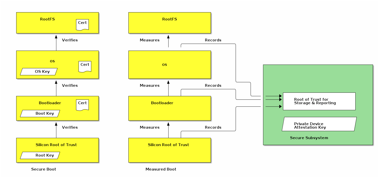
The device secure subsystem SHALL use the device attestation private key to sign attestation-elements and NOCSR-elements. The device secure subsystem SHALL fill the attestation-elements fields using information compiled into its image or generated during the measured boot process. The device secure subsystem SHALL validate all signing requests so that if the device software, but not its secure subsystem, gets compromised it cannot act as a signing oracle to sign Attestation Information Responses with fake Firmware Digests.
The firmware_information field in attestation-elements SHALL NOT be generated by devices that do not implement a separate secure subsystem, in software or hardware, which maintains and controls the use of the device attestation private key.
For devices that support secure boot, it is straightforward to add support for measured boot. Specifically, the hashes of the different firmware components that are already generated and verified sequentially during secure boot SHALL be collected and stored for reporting. Devices that do not support secure boot MAY implement measured boot by generating the hashes in software during the boot process implementing the root for measurement in the earliest firmware component.
If a device that chooses to send Firmware Digests and which supports an industry-standard measured boot architecture and which can generate signed firmware attestation reports, the secure subsystem in the device MAY validate the firmware attestation reports locally and SHALL report the raw firmware digests in attestation-elements so that the firmware_information field in attestation-elements has the same values in all devices of the same model that run the specific Software Image.
Firmware Digests SHALL NOT be reported by devices that implement a single firmware component in the boot chain, because there is nothing to measure and report subsequently, unless they have support for measured boot built in the device’s boot ROM.
Commissioners MAY use the reported firmware information to confirm that the firmware version is authorized to run on the device, that it has not been revoked, or that it does not contain known vulnerabilities. Commissioners and Administrators that choose to verify this information SHOULD refer to canonical databases, such as the Distributed Compliance Ledger (see Section 11.22, “Distributed Compliance Ledger”) to validate that the reported firmware information matches what is expected for an authorized Software Image associated with a given Certification Declaration. The firmware information, when validated, SHALL be validated as an opaque well-known octet string. Internal semantic validation MAY be applied for error-reporting, but the exact format is out of the scope of this specification.
In cases where a Commissioner or Administrator detects such an invalid or problematic firmware version, Commissioners and Administrators MAY, after consultation with the user, refuse to commission the device, provide it with operational credentials, or otherwise operate it, until the firmware has been updated, to avoid putting the user at risk from compromised software.
6.3.3. Firmware information validation examples
Below is an illustrative example of the Commissioner actions to validate the firmware information.
-
Retrieve the
firmware_informationfield from attestation-elements -
Retrieve all Distributed Compliance Ledger DeviceSoftwareVersionModel entries for the Commissionee’s Vendor ID and Product ID.
-
Verify that there is a valid, non-revoked, entry where the FirmwareInformation field exactly matches the
firmware_informationfield in attestation-elements. -
If verification fails, report error to the user
-
If verification succeeds, proceed with device commissioning
Below is an example of the corresponding Device actions. For illustrative purposes, it is assumed that the device implements a secure subsystem that maintains the private device attestation key and signs attestation-elements using this key but it does not have direct hardware support for measure boot. This is expected to be the common case for many devices covered by this version of the specification. Consequently, the measurement process can only start from the bootloader shown in the figure above.
-
The device bootloader produces a measurement of the OS kernel using a supported hash algorithm from RFC 5912 and delivers it to the secure subsystem.
-
The secure subsystem receives the measurement and stores in a location inaccessible to the OS.
-
The OS kernel produces a hash of the root filesystem and delivers the measurement to the secure subsystem.
-
When the secure subsystem is asked to sign an attestation-elements structure using its private device attestation key, it generates two FirmwareDigests or one combined FirmwareDigest from these measurements, fills the
firmware_informationfield in attestation-elements using these measurements, fills the CD blob compiled into the secure environment and signs the attestation-elements structure.
The Device Vendor is responsible to provide the FirmwareInformation field when a new Software Image entry is reported in the corresponding Distributed Compliance Ledger entry.
Below is an exemplary ASN.1 schema for an encoding scheme that could be used to encode firmware information.
HashAlgorithm ::= SEQUENCE {
id OBJECT IDENTIFIER,
params ANY OPTIONAL
}
FirmwareDigest ::= SEQUENCE {
digestAlgorithm HashAlgorithm,
digestHash OCTET STRING
}
FirmwareInformation ::= SEQUENCE {
firmwareDigests SEQUENCE OF FirmwareDigest
}
-- Example HashAlgorithm id
id-sha256 OBJECT IDENTIFIER ::= {
joint-iso-itu-t(2) country(16) us(840) organization(1) gov(101)
csor(3) nistAlgorithms(4) hashalgs(2) 1
}
-- Below is an example value for the above exemplary FirmwareInformation
firmwareInformation FirmwareInformation ::= {
-- The firmwareDigests contain two values, for two separate components.
firmwareDigests {
{
digestAlgorithm {
id id-sha256
},
digestHash '00112233445566778899AABBCCDDEEFF00112233445566778899AABBCCDDEEFF'H
},
{
digestAlgorithm {
id id-sha256
},
digestHash '101112131415161718191A1B1C1D1E1F101112131415161718191A1B1C1D1E1F'H
}
}
}The above example would yield the following DER-encoded octet string:
30663031 300d0609 60864801 65030402 01050004 20001122 33445566 778899AA BBCCDDEE FF001122 33445566 778899AA BBCCDDEE FF303130 0D060960 86480165 03040201 05000420 10111213 14151617 18191A1B 1C1D1E1F 10111213 14151617 18191A1B 1C1D1E1F
6.4. Node Operational Credentials Specification
6.4.1. Introduction
The Node Operational credentials are a collection of credentials to enable a Node to identify itself within a Fabric. The Node Operational credentials are distinct from the Device Attestation credentials. The Node Operational credentials are installed during Commissioning.
The Node Operational credentials include the following items:
Each Node in a Fabric is identified with a Node Operational Identifier. In order to securely identify the Node, the Node Operational Identifier is bound to the Node Operational Public Key as both are contained within the signed NOC. The Node Operational Identifier is a constituent part of the subject field of the NOC, according to the rules described in Matter DN Encoding Rules. A connecting Node can attest to the validity of the Node Operational Public Key and the Node Operational Identifier in a received NOC because the NOC is signed by a CA that the connecting Node trusts. Used with Certificate Authenticated Session Establishment (CASE), these data provide the basis for secure communications on the Fabric.
6.4.2. Node Operational Credentials Management
Commands from the Node Operational Credentials Cluster are used to install and update Node Operational credentials.
A Node receives its initial set of Node Operational credentials through the AddNOC command when it is commissioned onto a Fabric by a Commissioner.
Once installed, Node Operational credentials MAY be updated by an Administrator with the appropriate privileges using the UpdateNOC command.
Once installed, Node Operational credentials MAY be removed by an Administrator with the appropriate privileges using the RemoveFabric command. The removal uses RemoveFabric, since the Fabric association for the given Node Operational credentials may underpin a variety of bindings and other fabric-scoped configuration, which would remain in an inconsistent state if the Node Operational credentials alone were removed, as opposed to the entire associated Fabric and data.
6.4.3. Node Operational Identifier Composition
The Node Operational Identifier is used for Node discovery and network address resolution within a network segment. The FabricID portion of the Node Operational Identifier serves a scoping purpose to identify disjoint operational Fabrics within a given network segment. The NodeID portion of the Node Operational Identifier is the logical addressing identifier used:
-
within Message-layer messages for logical addressing (see Section 4.4, “Message Frame Format”)
-
within Data Model bindings to express data subscription relationships between Nodes (see System Model)
-
within Access Control List Entries to refer to individual Nodes as access control grantees (subjects) when CASE sessions are used for communication (see Access Control Cluster)
In addition to the FabricID and NodeID, a Node Operational Identifier MAY include at most three 32-bit CASEAuthenticatedTag (1.3.6.1.4.1.37244.1.6) attributes used to tag the operational identifier to implement access control based on CASE Authenticated Tags.
The Fabric ID is a 64-bit value that identifies the Fabric and is scoped to a particular Root CA. For example, two fabrics with the same Fabric ID are not equivalent unless their Root CA are the same. The Fabric ID MAY be chosen randomly or algorithmically but it SHALL be allocated uniquely within the set of all possible Fabric IDs for which a given Root CA will sign operational certificates. Before allocating the Fabric ID, the Commissioner SHOULD attempt to ensure that an existing Fabric is reused and joined, if any is applicable from the perspective of the Commissioner in the current commissioning context. The method used for determining local Fabric ID existence is vendor-specific.
The Node ID is a 64-bit value that identifies a Node within a Fabric. The Node ID MAY be chosen randomly or algorithmically but it SHALL be allocated uniquely within the Fabric before it is given to the Node or otherwise used. The Node ID SHALL be chosen, by a Commissioner, at the time of Node commissioning.
The uniqueness constraint for Fabric ID is only required to be ensured within the scope of the Root CA serving the Commissioner.
When a Fabric is removed, through the RemoveFabric command or through a factory reset, the Node Operational Identifier, and the FabricID and NodeID that comprise it, SHALL be permanently removed from the Node’s memory.
6.4.4. Node Operational Key Pair
A Node Operational Key Pair, comprised of a Node Operational Public Key and a Node Operational Private Key, is created using the Crypto_GenerateKeypair function. A new Node Operational Key Pair is generated for each Commissioning Session in accordance with security requirements.
6.4.5. Node Operational Credentials Certificates
All certificates in the Node Operational credentials are X.509v3 certificates compliant with RFC 5280, encoded in such a way that they respect the constraints in the Operational_Certificate section. They may be encoded as X.509v3 certificates or Matter Operational Certificates ("Matter Certificates" thereafter). The signature field of a certificate SHALL be calculated using the X.509v3 encoding of the certificate.
6.4.5.1. Node Operational Certificate (NOC)
The NOC SHALL be issued by either a Root CA trusted within the Fabric or by an Intermediate Certificate Authority (ICA) whose ICA certificate is directly issued by such a Root CA. The NOC is bound to the Node Operational Key Pair through the Node Operational Credential Signing Request (NOCSR).
The validity period specifies the time period for which a NOC is valid. For constrained or sleepy devices that lack accurate time, enforcement of an NOC’s validity period MAY be omitted.
6.4.5.2. Intermediate CA (ICA) Certificate
In the case where an intermediate CA (ICA) issues the NOC, the ICA certificate is used to attest to the validity of the NOC. The Root CA certificate associated with the issuer of the ICA certificate is used in turn to attest to the validity of the ICA certificate.
6.4.5.3. Trusted Root CA Certificates
Each Node has one or more trusted Root CA certificates in its Node Operational credentials that it uses to verify ICA certificates and Node Operational Certificates presented by other Nodes, treating them as trust anchors as described in RFC 5280. A Root CA certificate is self-signed. They are not verified but rather trusted because they were provisioned by a trusted Commissioner.
In the case where a Root CA issues the NOC, the Root CA certificate is used to attest to the validity of the NOC.
The trusted Root CA certificates that a Device trusts when the Device is verifying operational certificates are those stored in the TrustedRootCertificates attribute of that Device’s Node Operational Credentials cluster.
A device MAY have Root CA certificates that it trusts for purposes other than for operational credential verification. These certificates SHALL NOT appear in any Node’s TrustedRootCertificates attribute of the Node Operational Credentials cluster. The certificates configured in that cluster SHALL only be added during the commissioning process by the Commissioner, or during root rotation operations by an Administrator already trusted by the Node. Nodes SHALL NOT modify the TrustedRootCertificates attribute outside of the processing of Node Operational Credentials cluster commands.
The figures below show the Node Operational Certificate hierarchies, with and without optional ICAC.
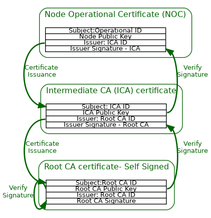
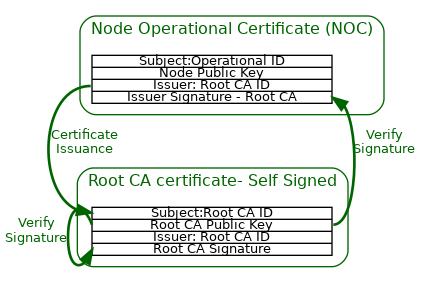
6.4.6. Node Operational Credentials Procedure
The following procedure is used by a Node to obtain an Operational Credential. This procedure is part of Commissioning.
6.4.6.1. Node Operational Certificate Signing Request (NOCSR) Procedure
After the Commissioner validates Device Attestation Information, the following procedure is used to generate a Node Operational Key Pair and obtain the NOCSR.
-
The Commissioner SHALL generate a random 32 byte nonce named
CSRNonceusingCrypto_DRBG(). -
The Commissioner SHALL send the CSRNonce to the Node and request NOCSR Information using the CSRRequest Command.
-
The Node SHALL create a new candidate Node Operational Key Pair, using
Crypto_GenerateKeyPair(), valid for the duration of the Fail-Safe Context currently in progress. -
The Node SHOULD verify that the newly generated candidate Node Operational Key Pair does not match any other existing Node Operational Key Pair on the device. If such a key collision was to be found, it would indicate a key pair that was not properly randomly generated. The procedure SHALL fail if such a collision is detected. See Section 11.17.7.5, “CSRRequest Command” for the error generated in that situation.
-
The candidate Node Operational Key Pair SHALL only be committed to persistent storage upon successful execution of the next AddNOC Command executed with a Node Operational Certificate whose public key matches the candidate key.
-
The Node SHALL create a Certificate Signing Request (CSR) by following the format and procedure in
PKCS #10, which includes a signature using the Node Operational Private Key (see RFC 2986 section 4.2). -
The CSR’s subject MAY be any value and the device SHOULD NOT expect the final operational certificate to contain any of the CSR’s subject DN attributes.
-
-
The Node SHALL generate and return the NOCSR Information (see Section 11.17.5.7, “NOCSR Information” for encoding) to the Commissioner using the CSRResponse Command. The NOCSR Information includes a signature using the Device Attestation Private Key.
Node Operational CSR Information Validation
-
The Commissioner SHALL validate the Device Attestation Signature (
attestation_signature) field from CSRResponse Command:Success = Crypto_Verify( publicKey = Public key from DAC, message = NOCSR Information TBS (nocsr_tbs), signature = Device Attestation Signature (attestation_signature) )where the fields are encoded as described in Section 11.17.5.7, “NOCSR Information”.
-
The
AttestationChallengeSHALL be obtained from a CASE session, resumed CASE session, or PASE session depending on the method used to establish the secure session within which device attestation is conducted. -
The CSR Nonce in NOCSR Information SHALL match the Commissioner’s CSR Nonce.
-
-
The inner signature in the PKCS#10
csrsub-field of the CSRResponse Command'sNOCSRElementsfield SHALL be verified, per the definition of CSR signatures inPKCS #10.
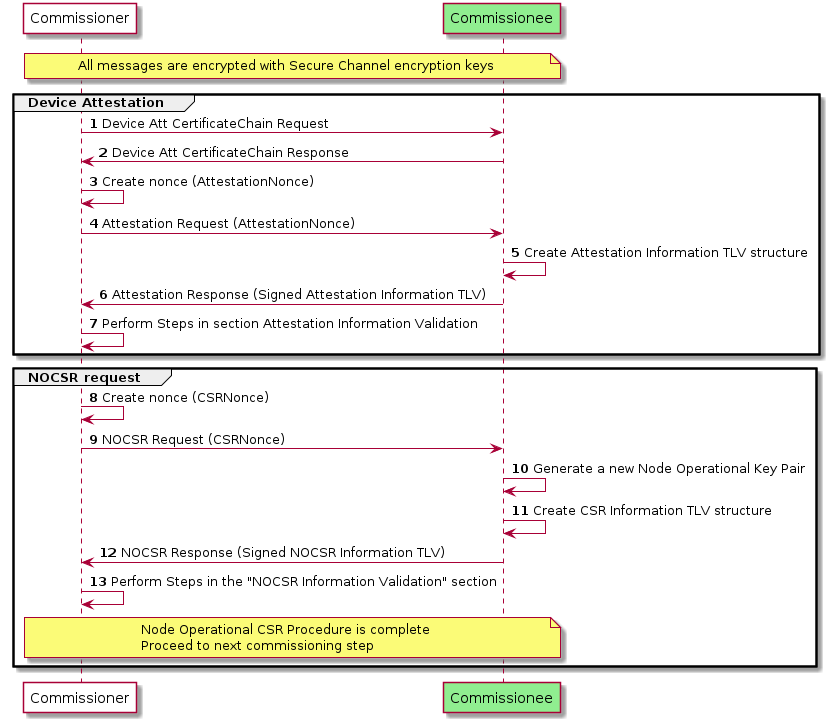
6.4.7. Node Operational Certificate Signing Request (NOCSR)
A Node creates a NOCSR in response to the Commissioner, so that the Commissioner can request a NOC on the Node’s behalf from its trusted Certificate Authority. The CSR itself SHALL follow the encoding and rules from PKCS #10, with the minimum attributes shown in the example below.
Note that the subject field MAY be any value.
Certificate Request:
Data:
Version: 1 (0x0)
Subject: ...............
Subject Public Key Info:
Public Key Algorithm: id-ecPublicKey
Public-Key: (256 bit)
pub:
04:12:3b:90:f5:.......
ASN1 OID: prime256v1
NIST CURVE: P-256
Attributes:
Requested Extensions:
Signature Algorithm: ecdsa-with-SHA256
30:46:02:21:00:95:ff:......6.4.8. Node Operational Certificate Renewal
A NOC can be renewed by an Administrator (a Node that has Administer privileges on the Node to be updated). The Administrator triggers the process by sending an CSRRequest Command.
6.4.9. Node Operational Certificate Revocation
A Node’s access to other Nodes can be revoked by removing the associated Node ID from Access Control Entry subjects where it appears. This action is taken by an Administrator which has the privilege to update the Access Control Cluster for its Nodes.
6.4.10. Security Considerations
A NOC is a Node’s credential to operate on a Fabric. It SHALL be protected against the following threats:
-
The Node Operational Private Key SHALL be protected from unauthorized access.
-
The Node Operational Private Key SHOULD never leave the device.
-
The NOC SHALL NOT contain information that may violate the user’s privacy.
-
The NOC SHALL be wiped if the Node is factory reset.
6.5. Operational Certificate Encoding
6.5.1. Introduction
This section details the Matter certificate data structure (hereafter "Matter certificate"), a specific encoding that is sometimes used as a compact alternative to the standard X.509 certificate format [RFC 5280] for bandwidth-efficient transmission. A Node Operational Certificate (NOC), Intermediate CA certificate and Root CA certificate MAY all be encoded as a Matter certificate.
To compress the structure more efficiently than an X.509 certificate, a Matter certificate SHALL be encoded with the Matter TLV structured data interchange language [Appendix A, Tag-length-value (TLV) Encoding Format] instead of the ASN.1 Distinguished Encoding Rules (DER) [X.690].
This section provides a technical specification of the structure of data comprising a Matter certificate with accompanying requirements for their semantic validation, and their conversion to and from X.509 certificates. In some cases, as noted, the limitations on the semantic interpretation of parts of a Matter certificate follow from limitations applied by [RFC 5280].
A certificate comprises a record of the following conceptual fields:
Certificate Text
Version Number
Serial Number
Signature Algorithm ID
Issuer Name
Validity period
Not Before
Not After
Subject name
Subject Public Key Info
Public Key Algorithm
Subject Public Key
Issuer Unique Identifier
Subject Unique Identifier
Extensions
Certificate Signature Algorithm
Certificate Signature
6.5.1.1. ASN.1 Object Identifiers (OID)
Several important components of X.509 certificates follow the pattern commonly used in ASN.1 data models where some types are constructed with an ASN.1 object identifier (OID) to identify each variant. For example, the cryptographic algorithm used in the digital signature is identified by its OID.
Matter certificates do not use ASN.1 OIDs. Instead, each valid ASN.1 OID SHALL be mapped to a Matter TLV tag within its reference category. Each reference category defines the context of the Matter tag, and tag values are assigned to the reference categories according to the type of fields where they can appear in X.509 certificates.
6.5.2. Matter certificate
A Matter certificate encodes a subset of the object identifiers (OIDs) specified in X.509. Only some attribute types for relative distinguished names are valid, only certain cryptographic algorithms (corresponding to the algorithms as defined in Chapter 3, Cryptographic Primitives) are used, and only a limited set of extensions are used. Therefore, every Matter certificate can be represented as a corresponding X.509 certificate. However, the converse is not true; not every X.509 certificate can be represented as a Matter certificate.
The signature included in a Matter certificate is the signatureValue of the corresponding X.509 certificate, not a signature of the preceding Matter TLV data in the Matter certificate structure. Accordingly, validating the signature in a Matter certificate entails its logical conversion to the corresponding X.509 certificate to recover the original tbsCertificate of the basic syntax signed by the Certificate Authority (CA).
matter-certificate [anonymous] => STRUCTURE [tag-order]
{
serial-num [1] : OCTET STRING [ length 0..20 ],
sig-algo [2] : signature-algorithm,
issuer [3] : LIST [ length 1.. ] OF dn-attribute,
not-before [4] : UNSIGNED INTEGER [ range 32-bits ],
not-after [5] : UNSIGNED INTEGER [ range 32-bits ],
subject [6] : LIST [ length 1.. ] OF dn-attribute,
pub-key-algo [7] : public-key-algorithm,
ec-curve-id [8] : elliptic-curve-id,
ec-pub-key [9] : OCTET STRING,
extensions [10] : LIST [ length 1.. ] OF extension,
signature [11] : ec-signature,
}
6.5.3. Version Number
Matter certificates SHALL only support version X.509 v3. This field is not encoded in the Matter certificate structure.
6.5.4. Serial Number
The context-specific tag serial-num [1] SHALL be used to identify the serial number field in the Matter certificate structure.
A Matter certificate follows the same limitation on admissible serial numbers as in [RFC 5280], i.e., that implementations SHALL admit serial numbers up to 20 octets in length, and certificate authorities SHALL NOT use serial numbers longer than 20 octets in length.
6.5.5. Signature Algorithm
Like an X.509 certificate, a Matter certificate SHALL include a digital signature in its signature component. The signature algorithm component of a Matter certificate specifies the cryptographic algorithm used for composing and validating the signature embedded in the signature component of the certificate. The signature algorithm SHALL match the algorithm in Section 3.5.3, “Signature and verification”.
The context-specific tag sig-algo [2] SHALL be used to identify the signature algorithm field in the Matter certificate structure.
signature-algorithm => UNSIGNED INTEGER [ range 8-bits ]
{
ecdsa-with-sha256 = 1,
}
The following values SHALL be defined for signature-algorithm:
| Value | ASN.1 OID |
|---|---|
1 |
iso(1) member-body(2) us(840) ansi-x962(10045) signatures(4) ecdsa-with-SHA2(3) ecdsa-with-SHA256(2) |
6.5.6. Issuer and Subject
The context-specific tags issuer [3] and subject [6] SHALL be used to identify the issuer and the subject DN fields in the Matter certificate structure. The entries in the lists SHALL be Distinguished Names (DNs), which are described in Section 6.5.6.1, “X.501 Distinguished Names”.
6.5.6.1. X.501 Distinguished Names
The Issuer Name and Subject Name components of an X.509 certificate contain DNs as defined in [RFC 5280]. The ASN.1 format of a DN is a sequence of Relative Distinguished Names (RDNs). Two distinguished names DN1 and DN2 match if they have the same number of RDNs, for each RDN in DN1 there is a matching RDN in DN2, and the matching RDNs appear in the same order in both DNs.
The RDN in an X.509 certificate may be encoded as a set of one or more DN attributes, although in practice it is usually a single DN attribute. The RDN in a Matter certificate SHALL be always a single DN attribute. Two relative distinguished names RDN1 and RDN2 match if the attribute in RDN1 matches the attribute in RDN2.
dn-attribute => CHOICE OF
{
// Standard and Matter-specific DN attributes.
// Of these, all are encoded as UTF8String except domain-component,
// which is encoded as IA5String in X.509 form.
common-name [1] : STRING,
surname [2] : STRING,
serial-num [3] : STRING,
country-name [4] : STRING,
locality-name [5] : STRING,
state-or-province-name [6] : STRING,
org-name [7] : STRING,
org-unit-name [8] : STRING,
title [9] : STRING,
name [10] : STRING,
given-name [11] : STRING,
initials [12] : STRING,
gen-qualifier [13] : STRING,
dn-qualifier [14] : STRING,
pseudonym [15] : STRING,
domain-component [16] : STRING,
matter-node-id [17] : UNSIGNED INTEGER,
matter-firmware-signing-id [18] : UNSIGNED INTEGER,
matter-icac-id [19] : UNSIGNED INTEGER,
matter-rcac-id [20] : UNSIGNED INTEGER,
matter-fabric-id [21] : UNSIGNED INTEGER,
matter-noc-cat [22] : UNSIGNED INTEGER,
// Standard DN attributes when encoded as PrintableString in X.509 form
// NOTE: The tags for these SHALL be the base tags + 0x80.
common-name-ps [129] : STRING,
surname-ps [130] : STRING,
serial-num-ps [131] : STRING,
country-name-ps [132] : STRING,
locality-name-ps [133] : STRING,
state-or-province-name-ps [134] : STRING,
org-name-ps [135] : STRING,
org-unit-name-ps [136] : STRING,
title-ps [137] : STRING,
name-ps [138] : STRING,
given-name-ps [139] : STRING,
initials-ps [140] : STRING,
gen-qualifier-ps [141] : STRING,
dn-qualifier-ps [142] : STRING,
pseudonym-ps [143] : STRING,
}
Table 56, “Standard DN Object Identifiers” lists the context-specific tags defined for the standard DN attribute types used in Matter that can be encoded in X.509 certificates as either UTF8String or as PrintableString format. In Matter certificates, the context-specific tag is logically-ORed with 0x80 (and its name given a corresponding -ps suffix) to indicate that the corresponding X.509 encoding of the attribute uses the PrintableString format instead of UTF8String.
| Tag base | Matter name base | ASN.1 OID |
|---|---|---|
1 |
|
joint_iso_ccitt(2) ds(5) attributeType(4) commonName(3) |
2 |
|
joint_iso_ccitt(2) ds(5) attributeType(4) surname(4) |
3 |
|
joint_iso_ccitt(2) ds(5) attributeType(4) serialNumber(5) |
4 |
|
joint_iso_ccitt(2) ds(5) attributeType(4) countryName(6) |
5 |
|
joint_iso_ccitt(2) ds(5) attributeType(4) localityName(7) |
6 |
|
joint_iso_ccitt(2) ds(5) attributeType(4) stateOrProvinceName(8) |
7 |
|
joint_iso_ccitt(2) ds(5) attributeType(4) organizationName(10) |
8 |
|
joint_iso_ccitt(2) ds(5) attributeType(4) organizationalUnitName(11) |
9 |
|
joint_iso_ccitt(2) ds(5) attributeType(4) title(12) |
10 |
|
joint_iso_ccitt(2) ds(5) attributeType(4) name(41) |
11 |
|
joint_iso_ccitt(2) ds(5) attributeType(4) givenName(42) |
12 |
|
joint_iso_ccitt(2) ds(5) attributeType(4) initials(43) |
13 |
|
joint_iso_ccitt(2) ds(5) attributeType(4) generationQualifier(44) |
14 |
|
joint_iso_ccitt(2) ds(5) attributeType(4) dnQualifier(46) |
15 |
|
joint_iso_ccitt(2) ds(5) attributeType(4) pseudonym(65) |
Table 57, “Standard DN Domain Component Object Identifier” lists the context-specific tag defined for the standard DN attribute type used in Matter that is encoded in X.509 certificates as IA5String.
| Tag | Matter name | ASN.1 OID |
|---|---|---|
16 |
|
itu_t(0) data(9) pss(2342) ucl(19200300) pilot(100) pilotAttributeType(1) domainComponent(25) |
In addition to the standard DN attribute types, there are Matter-specific DN attribute types under the 1.3.6.1.4.1.1.37244 private arc. See Section 6.1.1, “Encoding of Matter-specific RDNs” for constraints and examples related to usage of Matter-specific DN attribute types.
6.5.6.2. Matter Certificate Types
The Matter-specific DN attribute types convey information about Matter-specific certificate types as listed in Table 58, “Matter Certificate Types”.
| Matter name | Description |
|---|---|
|
Certifies the identity of a Matter Node Operational Certificate (NOC). |
|
Certifies the identity of a firmware signing certificate. |
|
Certifies the identity of a Matter Intermediate CA (ICA) Certificate. |
|
Certifies the identity of a Matter Root CA Certificate. |
The value of matter-icac-id and matter-rcac-id DN attribute types MAY be any 64-bit identifier desired by the certificate’s issuer. Apart from marking what type of certificates are involved, they MAY be used for debugging purposes to determine the specific CA in use, for example if different production tiers or regions are used.
6.5.6.3. Matter DN Encoding Rules
The rules that SHALL be followed for Matter-specific attribute types when encoding the subject DN are:
-
For a Matter Node Operational Certificate (NOC):
-
The subject DN SHALL encode exactly one
matter-node-idattribute.-
The
matter-node-idattribute’s value SHALL be in the Operational Node ID range (0x0000_0000_0000_0001 to 0xFFFF_FFEF_FFFF_FFFF), see Table 4, “Node Identifier Allocations”.
-
-
The subject DN SHALL encode exactly one
matter-fabric-idattribute.-
The
matter-fabric-idattribute’s value SHALL NOT be 0 (see Section 2.5.1, “Fabric References and Fabric Identifier”).
-
-
The subject DN SHALL NOT encode any
matter-icac-idattribute. -
The subject DN SHALL NOT encode any
matter-rcac-idattribute. -
The subject DN MAY encode at most three
matter-noc-catattributes.-
Each
matter-noc-catattribute present, if any, SHALL encode a different CASE Authenticated Tag identifier (upper 16 bits of value) than is used by othermatter-noc-catattributes (CATs).
-
-
-
For a Matter ICA Certificate:
-
The subject DN SHALL NOT encode any
matter-node-idattribute. -
The subject DN MAY encode at most one
matter-fabric-idattribute.-
If present, the
matter-fabric-idattribute’s value SHALL NOT be 0 (see Section 2.5.1, “Fabric References and Fabric Identifier”).
-
-
The subject DN MAY encode at most one
matter-icac-idattribute. -
The subject DN SHALL NOT encode any
matter-rcac-idattribute. -
The subject DN SHALL NOT encode any
matter-noc-catattribute.
-
-
For a Matter Root CA Certificate:
-
The subject DN SHALL NOT encode any
matter-node-idattribute. -
The subject DN MAY encode at most one
matter-fabric-idattribute.-
If present, the
matter-fabric-idattribute’s value SHALL NOT be 0 (see Section 2.5.1, “Fabric References and Fabric Identifier”).
-
-
The subject DN SHALL NOT encode any
matter-icac-idattribute. -
The subject DN MAY encode at most one
matter-rcac-idattribute. -
The subject DN SHALL NOT encode any
matter-noc-catattribute.
-
-
The attributes SHALL appear in the same order in the Matter certificate and in the corresponding X.509 certificates.
-
When any
matter-fabric-idattributes are present in either the Matter Root CA Certificate or the Matter ICA Certificate, the value SHALL match the one present in the Matter Node Operational Certificate (NOC) within the same certificate chain. -
The order of the attributes can be issuer-specific and is not enforced by Matter specifications.
-
All implementations SHALL accept, parse, and handle Matter certificates with up to 5 RDNs in a single DN.
-
All implementations SHALL reject Matter certificates with more than 5 RDNs in a single DN.
In addition to the above rules, the encoding constraints in Section 6.1.1, “Encoding of Matter-specific RDNs” SHALL be followed.
6.5.6.4. Matter DN Examples
The following is an example of subject DN encoding for a Matter Node Operational Certificate (NOC). Typically, it is a list of two RDN attributes:
subject = [[
matter-node-id = 0x0102030405060708U,
matter-fabric-id = 0xFAB000000000001DU
]]
In addition to the mandatory attributes, it may also encode other supported RDN attributes such as common-name and CASE Authenticated Tags as presented below:
subject = [[
common-name = "NOC Example",
matter-node-id = 0x0102030405060708U,
matter-fabric-id = 0xFAB000000000001DU,
matter-noc-cat = 0xABCD0002U
]]
The following subject DN example illustrates that multiple RDN attributes of the same type can be encoded. The specific order of attributes is not enforced. Note that number of RDN attributes in the subject field SHALL NOT exceed five:
subject = [[
matter-noc-cat = 0xABCD0004U,
matter-node-id = 0x0102030405060708U,
matter-noc-cat = 0xABCE0018U,
matter-fabric-id = 0xFAB000000000001DU,
matter-noc-cat = 0xABCF0002U
]]
The following example illustrates an illegal subject DN due to the presence of the same CASE Authenticated Tag value with two different version numbers.
subject = [[
matter-node-id = 0x0102030405060708U,
matter-fabric-id = 0xFAB000000000001DU,
matter-noc-cat = 0xABCD0004U, # <-- Value 0xABCD, Version 0x0004
matter-noc-cat = 0xABCD0002U, # <-- Value 0xABCD, Version 0x0002
]]
The following is an example of subject DN encoding for a Matter Root CA certificate. In this case, the Matter Root CA certificate is not associated with a specific Matter fabric:
subject = [[
matter-rcac-id = 0xCA0000000000001DU
]]
The following is another example of subject DN encoding for a Matter Root CA certificate. In this case, the Matter Root CA certificate is associated with a specific Matter fabric. This DN also encodes an issuer-specific common-name RDN attribute:
subject = [[
matter-rcac-id = 0xCA0000000000001DU,
matter-fabric-id = 0xFAB000000000001DU,
common-name = "ROOT CA HOME 3"
]]
6.5.7. Validity
The context-specific tags not-before [4] and not-after [5] SHALL be used to identify the not-before and not-after fields in the Matter certificate structure, which indicate the period of validity for the certificate. These two fields SHALL be encoded as unsigned integers. The value of these fields SHALL be encoded as a UTC time of type epoch-s (Epoch Time in Seconds).
Special value 0, when encoded in the not-after field, corresponds to the X.509/RFC 5280 defined special time value 99991231235959Z meaning no well-defined expiration date.
6.5.8. Public Key Algorithm
The context-specific tag pub-key-algo [7] SHALL be used to identify the public key algorithm field in the Matter certificate structure.
public-key-algorithm => UNSIGNED INTEGER [ range 8-bits ]
{
ec-pub-key = 1,
}
The following values SHALL be defined for public-key-algorithm:
| Value | ASN.1 OID |
|---|---|
1 |
iso(1) member-body(2) us(840) ansi-x962(10045) keyType(2) ecPublicKey(1) |
6.5.9. EC Curve Identifier
The context-specific tag ec-curve-id [8] SHALL be used to identify the elliptic curve field in the Matter certificate structure.
elliptic-curve-id => UNSIGNED INTEGER [ range 8-bits ]
{
prime256v1 = 1,
}
The following values SHALL be defined for elliptic-curve-id:
| Value | ASN.1 OID |
|---|---|
1 |
iso(1) member_body(2) us(840) ansi-x962(10045) curves(3) prime(1) prime256v1(7) |
6.5.10. Public Key
The context-specific tag ec-pub-key [9] SHALL be used to identify the elliptic curve public key material field in the Matter certificate structure. The public key SHALL be a byte string representation of an uncompressed elliptic curve point as defined in section 2.3.3 of SEC1.
6.5.11. Extensions
The context-specific tag extensions [10] SHALL be used to identify the extensions field in the Matter certificate structure. The extensions list SHALL NOT contain more than one instance of a particular extension. The following table summarizes context-specific tags defined for the certificate extension types used in Matter.
extension => CHOICE OF
{
basic-cnstr [1] : basic-constraints,
key-usage [2] : UNSIGNED INTEGER [ range 16-bits ],
extended-key-usage [3] : ARRAY [ length 1.. ] OF key-purpose-id,
subject-key-id [4] : OCTET STRING [ length 20 ],
authority-key-id [5] : OCTET STRING [ length 20 ],
future-extension [6] : OCTET STRING,
}
| Tag | Matter Name | ASN.1 OID |
|---|---|---|
1 |
|
joint-iso-itu-t(2) ds(5) certificateExtension(29) basicConstraints(19) |
2 |
|
joint-iso-itu-t(2) ds(5) certificateExtension(29) keyUsage(15) |
3 |
|
joint-iso-itu-t(2) ds(5) certificateExtension(29) extendedKeyUsage(37) |
4 |
|
joint-iso-itu-t(2) ds(5) certificateExtension(29) subjectKeyIdentifier(14) |
5 |
|
joint-iso-itu-t(2) ds(5) certificateExtension(29) authorityKeyIdentifier(35) |
6 |
|
any valid ASN.1 OID (future extension) |
These context-specific tags identify the extension entries in the extensions list. The type of each extension is further described in the subsections below.
6.5.11.1. Basic Constraints Extension
The basic constraints extension identifies whether the subject of the certificate is a CA and the maximum depth of valid certification paths that include this certificate.
When present, the basic constraints extension SHALL be treated as critical and it SHALL be marked as critical in the corresponding X.509 certificate. The critical field SHALL NOT be encoded in the Matter certificate structure.
The context-specific tag basic-cnstr [1] SHALL be used to identify a basic constraints extension entry in the Matter certificate extensions list.
basic-constraints => STRUCTURE [tag-order]
{
is-ca [1] : BOOLEAN,
path-len-constraint [2, optional] : UNSIGNED INTEGER [ range 8-bits ],
}
The is-ca field SHALL be encoded regardless of the value (true or false). The path-len-constraint MAY be present only when is-ca == true.
6.5.11.2. Key Usage Extension
The key usage extension defines the purpose of the key contained in the certificate.
When present, the key usage extension SHALL be treated as critical and it SHALL be marked as critical in the corresponding X.509 certificate. The critical field SHALL NOT be encoded in the Matter certificate structure.
The context-specific tag number key-usage [2] SHALL be used to identify a key usage extension entry in the Matter certificate extensions list.
The key-usage field is derived as a logical OR of all key-usage-flag values that apply to the corresponding public key:
key-usage-flag => UNSIGNED INTEGER [ range 16-bits ]
{
digitalSignature = 0x0001,
nonRepudiation = 0x0002,
keyEncipherment = 0x0004,
dataEncipherment = 0x0008,
keyAgreement = 0x0010,
keyCertSign = 0x0020,
CRLSign = 0x0040,
encipherOnly = 0x0080,
decipherOnly = 0x0100,
}
6.5.11.3. Extended Key Usage Extension
The extended key usage extension indicates one or more purposes for which the certified public key may be used, in addition to or in place of the basic purposes indicated in the key usage extension.
When present, the extended key usage extension SHALL be treated as critical and it SHALL be marked as critical in the corresponding X.509 certificate. The critical field SHALL NOT be encoded in the Matter certificate structure.
The context-specific tag number extended-key-usage [3] SHALL be used to identify an extended key usage extension entry in the Matter certificate extensions list.
The extended-key-usage field SHALL be encoded as an array of key-purpose-id values, where each key-purpose-id value SHALL be encoded as 8-bit unsigned integer:
key-purpose-id => UNSIGNED INTEGER [ range 8-bits ]
The following values SHALL be defined for key-purpose-id:
| Value | ASN.1 OID |
|---|---|
1 |
iso(1), organization(3), dod(6), internet(1), security(5), mechanisms(5), pkix(7), 3, serverAuth(1) |
2 |
iso(1), organization(3), dod(6), internet(1), security(5), mechanisms(5), pkix(7), 3, clientAuth(2) |
3 |
iso(1), organization(3), dod(6), internet(1), security(5), mechanisms(5), pkix(7), 3, codeSigning(3) |
4 |
iso(1), organization(3), dod(6), internet(1), security(5), mechanisms(5), pkix(7), 3, emailProtection(4) |
5 |
iso(1), organization(3), dod(6), internet(1), security(5), mechanisms(5), pkix(7), 3, timeStamping(8) |
6 |
iso(1), organization(3), dod(6), internet(1), security(5), mechanisms(5), pkix(7), 3, OCSPSigning(9) |
The key-purpose-id values in the extended-key-usage array SHALL be encoded in the same order as they appeared in the corresponding X.509 certificate.
6.5.11.4. Subject Key Identifier Extension
The subject key identifier extension provides a means of identifying Matter certificates that contain a particular public key.
When present, the subject key identifier extension SHALL be treated as non-critical and it SHALL be marked as non-critical in the corresponding X.509 certificate. The critical field SHALL NOT be encoded in the Matter certificate structure.
The context-specific tag number subject-key-id [4] SHALL be used to identify a subject key identifier extension entry in the Matter certificate extensions list.
The Subject Key Identifier field SHALL be derived from the public key using method (1) described in section 4.2.1.2 of [RFC 5280]. Thus, the subject-key-id SHALL be composed of the 160-bit SHA-1 hash of the certificate’s subject public key value.
See Section 6.1.2, “Key Identifier Extension Constraints” for additional constraints.
6.5.11.5. Authority Key Identifier Extension
The authority key identifier extension provides a means of identifying the public key corresponding to the private key used to sign a Matter certificate.
When present, the authority key identifier extension SHALL be treated as non-critical and it SHALL be marked as non-critical in the corresponding X.509 certificate. The critical field SHALL NOT be encoded in the Matter certificate structure.
The context-specific tag number authority-key-id [5] SHALL be used to identify an authority key identifier extension entry in the Matter certificate extensions list.
Note that the authority key identifier extension field in an X.509 certificate may optionally include issuer and serial number fields, which are not supported by Matter certificates.
The Authority Key Identifier field SHALL be derived from the public key using method (1) described in section 4.2.1.2 of [RFC 5280]. Thus, the authority-key-id SHALL be composed of the 160-bit SHA-1 hash of the public key used to verify the certificate’s signature.
See Section 6.1.2, “Key Identifier Extension Constraints” for additional constraints.
6.5.11.6. Future Extension
The Matter certificate is designed with extensibility in mind and this field is added to support arbitrary certificate extension in the future.
Note that implementations that do not support specific future extension will ignore it but will be able to use it for the Matter certificate signature validation. If ignored extension is marked as critical then validation of the corresponding Matter certificate SHALL fail.
The context-specific tag number future-extension [6] SHALL be used to identify all future extension entries in the Matter certificate extensions list. There MAY be more than one future extension field.
The future-extension field SHALL be encoded as OCTET STRING and it SHALL be an exact copy of the DER encoded extension field (including the DER encoded ASN.1 OID of the extension) in the corresponding X.509 certificate. These extension fields in a Matter certificate SHALL be encoded in the same order as they appeared in the original X.509 certificate.
6.5.12. Matter certificate Extensions Encoding Rules
The rules that SHALL be followed when encoding the Matter certificate are:
-
For a Matter Node Operational Certificate (NOC):
-
The basic constraints extension SHALL be encoded with
is-caset tofalse. -
The key usage extension SHALL be encoded with exactly one flag:
digitalSignature. -
The extended key usage extension SHALL be encoded with exactly two key-purpose-id values:
serverAuthandclientAuth. -
The subject key identifier extension SHALL be present.
-
The authority key identifier extension SHALL be present.
-
-
For Matter ICA Certificate and Matter Root CA Certificate:
-
The basic constraints extension SHALL be encoded with
is-caset totrue. -
The key usage extension SHALL be encoded with exactly two flags:
keyCertSignandCRLSign. -
The extended key usage extension SHALL NOT be present.
-
The subject key identifier extension SHALL be present.
-
The authority key identifier extension SHALL be present.
-
For the Matter Root CA Certificate the authority key identifier extension SHALL be equal to the subject key identifier extension.
-
-
For a Matter Firmware Signing Certificate these rules SHALL be followed:
-
The basic constraints extension SHALL be encoded with
is-caset tofalse. -
The key usage extension SHALL be encoded with exactly one flag:
digitalSignature. -
The extended key usage extension SHALL be encoded with exactly one key-purpose-id values:
codeSigning. -
The subject key identifier extension SHALL be present.
-
The authority key identifier extension SHALL be present.
-
-
The extensions SHALL appear in the same order in the Matter certificate and in the corresponding X.509 certificates.
Note that Matter doesn’t specify how firmware images are signed and implementation of firmware image signing is manufacturer-specific. However, since firmware image signing is a common feature, the format for Matter TLV certificates has affordances for encoding firmware signing certificates.
6.5.13. Signature
The context-specific tag signature [11] SHALL be used to identify the signature field in the Matter certificate structure.
An ec-signature is the encoding of the signature as defined in Section 3.5.3, “Signature and verification”.
ec-signature => OCTET STRING [ length (CRYPTO_GROUP_SIZE_BYTES * 2) ]
6.5.14. Invalid Matter certificates
The Matter certificate is considered invalid if it violates Matter certificate encoding rules defined in this section. The processing of invalid Matter certificate SHOULD fail and an error SHOULD be reported to the application. Here is a non-exhaustive list of errors that may invalidate the certificate:
-
Matter certificate structure includes elements that are not defined in this section.
-
Matter certificate elements are encoded in a wrong order.
-
Matter certificate element has wrong type.
-
Length of an element is outside of its valid range, for example:
-
serial-numfield is longer than 20 octets. -
not-beforeornot-afterfield is longer than 32-bits. -
subject-key-idorauthority-key-idfield is different from 20 octets.
-
-
Matter OID values encoded in Matter certificate are not defined in this section, for example:
-
sig-algofield encodes value, which is not defined in Table 55, “Signature Algorithm Object Identifiers”. -
pub-key-algofield encodes value, which is not defined in Table 59, “Public Key Algorithm Object Identifiers”. -
ec-curve-idfield encodes value, which is not defined in Table 60, “Elliptic Curve Object Identifiers”. -
key-purpose-idfield of the Extended Key Usage Extension encodes value, which is not defined in Table 62, “Key Purpose Object Identifiers”.
-
-
Invalid Matter Distinguished Names encoding for Issuer and Subject DNs. Refer to Section 6.5.6.3, “Matter DN Encoding Rules” for more details. For example:
-
Node Subject DN doesn’t include Matter specific
matter-node-idormatter-fabric-idattribute. -
Firmware signing Subject DN doesn’t include Matter specific
matter-firmware-signing-idattribute. -
Intermediate CA Subject DN doesn’t include Matter specific
matter-icac-idattribute. -
Root CA Subject DN doesn’t include Matter specific
matter-rcac-idattribute. -
Certificate Subject DN encodes
matter-node-idandmatter-rcac-id, which contradict each other. -
Multiple
matter-cat-idwith the same identifier value and different version numbers, or anymatter-cat-idwith a version number of 0.
-
-
CA certificate doesn’t have Basic Constraints Extension
is-cafield set to 'true'. -
key-usagefield of the Key Usage Extension has undefined flags. -
Certificate extension that SHALL be marked as
criticalis marked asnon-criticalin the X.509 representation and vise versa.
6.5.15. Examples
6.5.15.1. Example of Operational Root CA Certificate (RCAC)
The same RCAC in X.509 and Matter TLV formats is presented in this section.
-----BEGIN CERTIFICATE-----
MIIBnTCCAUOgAwIBAgIIWeqmMpR/VBwwCgYIKoZIzj0EAwIwIjEgMB4GCisGAQQB
gqJ8AQQMEENBQ0FDQUNBMDAwMDAwMDEwHhcNMjAxMDE1MTQyMzQzWhcNNDAxMDE1
MTQyMzQyWjAiMSAwHgYKKwYBBAGConwBBAwQQ0FDQUNBQ0EwMDAwMDAwMTBZMBMG
ByqGSM49AgEGCCqGSM49AwEHA0IABBNTo7PvHacIxJCASAFOQH1ZkM4ivE6zPppa
yyWoVgPrptzYITZmpORPWsoT63Z/r6fc3dwzQR+CowtUPdHSS6ijYzBhMA8GA1Ud
EwEB/wQFMAMBAf8wDgYDVR0PAQH/BAQDAgEGMB0GA1UdDgQWBBQTr4GrNzdLLtKp
ZJsSt6OkKH4VHTAfBgNVHSMEGDAWgBQTr4GrNzdLLtKpZJsSt6OkKH4VHTAKBggq
hkjOPQQDAgNIADBFAiBFgWRGbI8ZWrwKu3xstaJ6g/QdN/jVO+7FIKvSoNoFCQIh
ALinwlwELjDPZNww/jNOEgAZZk5RUEkTT1eBI4RE/HUx
-----END CERTIFICATE-----
-----BEGIN EC PRIVATE KEY-----
MHcCAQEEIH1zW+/pFqHAygL4ypiB5CZjqq+aucQzsom+JnAQdXQaoAoGCCqGSM49
AwEHoUQDQgAEE1Ojs+8dpwjEkIBIAU5AfVmQziK8TrM+mlrLJahWA+um3NghNmak
5E9ayhPrdn+vp9zd3DNBH4KjC1Q90dJLqA==
-----END EC PRIVATE KEY-----Certificate:
Data:
Version: 3 (0x2)
Serial Number: 6479173750095827996 (0x59eaa632947f541c)
Signature Algorithm: ecdsa-with-SHA256
Issuer: 1.3.6.1.4.1.37244.1.4 = CACACACA00000001
Validity
Not Before: Oct 15 14:23:43 2020 GMT
Not After : Oct 15 14:23:42 2040 GMT
Subject: 1.3.6.1.4.1.37244.1.4 = CACACACA00000001
Subject Public Key Info:
Public Key Algorithm: id-ecPublicKey
Public-Key: (256 bit)
pub:
04:13:53:a3:b3:ef:1d:a7:08:c4:90:80:48:01:4e:
40:7d:59:90:ce:22:bc:4e:b3:3e:9a:5a:cb:25:a8:
56:03:eb:a6:dc:d8:21:36:66:a4:e4:4f:5a:ca:13:
eb:76:7f:af:a7:dc:dd:dc:33:41:1f:82:a3:0b:54:
3d:d1:d2:4b:a8
ASN1 OID: prime256v1
NIST CURVE: P-256
X509v3 extensions:
X509v3 Basic Constraints: critical
CA:TRUE
X509v3 Key Usage: critical
Certificate Sign, CRL Sign
X509v3 Subject Key Identifier:
13:AF:81:AB:37:37:4B:2E:D2:A9:64:9B:12:B7:A3:A4:28:7E:15:1D
X509v3 Authority Key Identifier:
keyid:13:AF:81:AB:37:37:4B:2E:D2:A9:64:9B:12:B7:A3:A4:28:7E:15:1D
Signature Algorithm: ecdsa-with-SHA256
30:45:02:20:45:81:64:46:6c:8f:19:5a:bc:0a:bb:7c:6c:b5:
a2:7a:83:f4:1d:37:f8:d5:3b:ee:c5:20:ab:d2:a0:da:05:09:
02:21:00:b8:a7:c2:5c:04:2e:30:cf:64:dc:30:fe:33:4e:12:
00:19:66:4e:51:50:49:13:4f:57:81:23:84:44:fc:75:3115 30 01 08 59 ea a6 32 94 7f 54 1c 24 02 01 37 03 27 14 01 00 00 00 ca
ca ca ca 18 26 04 ef 17 1b 27 26 05 6e b5 b9 4c 37 06 27 14 01 00 00 00
ca ca ca ca 18 24 07 01 24 08 01 30 09 41 04 13 53 a3 b3 ef 1d a7 08 c4
90 80 48 01 4e 40 7d 59 90 ce 22 bc 4e b3 3e 9a 5a cb 25 a8 56 03 eb a6
dc d8 21 36 66 a4 e4 4f 5a ca 13 eb 76 7f af a7 dc dd dc 33 41 1f 82 a3
0b 54 3d d1 d2 4b a8 37 0a 35 01 29 01 18 24 02 60 30 04 14 13 af 81 ab
37 37 4b 2e d2 a9 64 9b 12 b7 a3 a4 28 7e 15 1d 30 05 14 13 af 81 ab 37
37 4b 2e d2 a9 64 9b 12 b7 a3 a4 28 7e 15 1d 18 30 0b 40 45 81 64 46 6c
8f 19 5a bc 0a bb 7c 6c b5 a2 7a 83 f4 1d 37 f8 d5 3b ee c5 20 ab d2 a0
da 05 09 b8 a7 c2 5c 04 2e 30 cf 64 dc 30 fe 33 4e 12 00 19 66 4e 51 50
49 13 4f 57 81 23 84 44 fc 75 31 18matter-certificate = {
serial-num = 59 EA A6 32 94 7F 54 1C,
sig-algo = 0x01U,
issuer = [[ matter-rcac-id = 0xCACACACA00000001U ]],
not-before = 0x271B17EFU,
not-after = 0x4CB9B56EU,
subject = [[ matter-rcac-id = 0xCACACACA00000001U ]],
pub-key-algo = 0x01U,
ec-curve-id = 0x01U,
ec-pub-key = 04 13 53 A3 B3 EF 1D A7 08 C4 90 80 48 01 4E 40
7D 59 90 CE 22 BC 4E B3 3E 9A 5A CB 25 A8 56 03
EB A6 DC D8 21 36 66 A4 E4 4F 5A CA 13 EB 76 7F
AF A7 DC DD DC 33 41 1F 82 A3 0B 54 3D D1 D2 4B
A8,
extensions = [[
basic-constraints = {
is-ca = true
},
key-usage = 0x60U,
subject-key-id = 13 AF 81 AB 37 37 4B 2E D2 A9 64 9B 12 B7 A3 A4
28 7E 15 1D,
authority-key-id = 13 AF 81 AB 37 37 4B 2E D2 A9 64 9B 12 B7 A3 A4
28 7E 15 1D,
]],
signature = 45 81 64 46 6C 8F 19 5A BC 0A BB 7C 6C B5 A2 7A
83 F4 1D 37 F8 D5 3B EE C5 20 AB D2 A0 DA 05 09
B8 A7 C2 5C 04 2E 30 CF 64 DC 30 FE 33 4E 12 00
19 66 4E 51 50 49 13 4F 57 81 23 84 44 FC 75 31
}
6.5.15.2. Example of Operational Intermediate CA Certificate (ICAC)
The same ICAC in X.509 and Matter TLV formats is presented in this section. An issuer of this ICAC is RCAC from previous section.
-----BEGIN CERTIFICATE-----
MIIBnTCCAUOgAwIBAgIILbREhVZBrt8wCgYIKoZIzj0EAwIwIjEgMB4GCisGAQQB
gqJ8AQQMEENBQ0FDQUNBMDAwMDAwMDEwHhcNMjAxMDE1MTQyMzQzWhcNNDAxMDE1
MTQyMzQyWjAiMSAwHgYKKwYBBAGConwBAwwQQ0FDQUNBQ0EwMDAwMDAwMzBZMBMG
ByqGSM49AgEGCCqGSM49AwEHA0IABMXQhhu4+QxAXBIxTkxevuqTn3J3S8wzI54v
Wfb0avjcfUaCoOPMxkbm3ynqhr9WKucgqJgzfTg/MsCgnkFgGeqjYzBhMA8GA1Ud
EwEB/wQFMAMBAf8wDgYDVR0PAQH/BAQDAgEGMB0GA1UdDgQWBBRTUtcFnpwVpQiQ
aGKGSAGinx9B0zAfBgNVHSMEGDAWgBQTr4GrNzdLLtKpZJsSt6OkKH4VHTAKBggq
hkjOPQQDAgNIADBFAiEAhBoG1Dten+zSToexJE61HGos8g2bXmugfxHmAC9+DKMC
IE4ypgLDYJ0AktNIvb0ZihFGRr1BzxA3g2Qa4l4/I/0m
-----END CERTIFICATE-----
-----BEGIN EC PRIVATE KEY-----
MHcCAQEEIBGEO9zwrSBtsQJRpU2sWB11+ZL8tSJ1KiFs15xxdUapoAoGCCqGSM49
AwEHoUQDQgAExdCGG7j5DEBcEjFOTF6+6pOfcndLzDMjni9Z9vRq+Nx9RoKg48zG
RubfKeqGv1Yq5yComDN9OD8ywKCeQWAZ6g==
-----END EC PRIVATE KEY-----Certificate:
Data:
Version: 3 (0x2)
Serial Number: 3293332566983159519 (0x2db444855641aedf)
Signature Algorithm: ecdsa-with-SHA256
Issuer: 1.3.6.1.4.1.37244.1.4 = CACACACA00000001
Validity
Not Before: Oct 15 14:23:43 2020 GMT
Not After : Oct 15 14:23:42 2040 GMT
Subject: 1.3.6.1.4.1.37244.1.3 = CACACACA00000003
Subject Public Key Info:
Public Key Algorithm: id-ecPublicKey
Public-Key: (256 bit)
pub:
04:c5:d0:86:1b:b8:f9:0c:40:5c:12:31:4e:4c:5e:
be:ea:93:9f:72:77:4b:cc:33:23:9e:2f:59:f6:f4:
6a:f8:dc:7d:46:82:a0:e3:cc:c6:46:e6:df:29:ea:
86:bf:56:2a:e7:20:a8:98:33:7d:38:3f:32:c0:a0:
9e:41:60:19:ea
ASN1 OID: prime256v1
NIST CURVE: P-256
X509v3 extensions:
X509v3 Basic Constraints: critical
CA:TRUE
X509v3 Key Usage: critical
Certificate Sign, CRL Sign
X509v3 Subject Key Identifier:
53:52:D7:05:9E:9C:15:A5:08:90:68:62:86:48:01:A2:9F:1F:41:D3
X509v3 Authority Key Identifier:
keyid:13:AF:81:AB:37:37:4B:2E:D2:A9:64:9B:12:B7:A3:A4:28:7E:15:1D
Signature Algorithm: ecdsa-with-SHA256
30:45:02:21:00:84:1a:06:d4:3b:5e:9f:ec:d2:4e:87:b1:24:
4e:b5:1c:6a:2c:f2:0d:9b:5e:6b:a0:7f:11:e6:00:2f:7e:0c:
a3:02:20:4e:32:a6:02:c3:60:9d:00:92:d3:48:bd:bd:19:8a:
11:46:46:bd:41:cf:10:37:83:64:1a:e2:5e:3f:23:fd:2615 30 01 08 2d b4 44 85 56 41 ae df 24 02 01 37 03 27 14 01 00 00 00 ca
ca ca ca 18 26 04 ef 17 1b 27 26 05 6e b5 b9 4c 37 06 27 13 03 00 00 00
ca ca ca ca 18 24 07 01 24 08 01 30 09 41 04 c5 d0 86 1b b8 f9 0c 40 5c
12 31 4e 4c 5e be ea 93 9f 72 77 4b cc 33 23 9e 2f 59 f6 f4 6a f8 dc 7d
46 82 a0 e3 cc c6 46 e6 df 29 ea 86 bf 56 2a e7 20 a8 98 33 7d 38 3f 32
c0 a0 9e 41 60 19 ea 37 0a 35 01 29 01 18 24 02 60 30 04 14 53 52 d7 05
9e 9c 15 a5 08 90 68 62 86 48 01 a2 9f 1f 41 d3 30 05 14 13 af 81 ab 37
37 4b 2e d2 a9 64 9b 12 b7 a3 a4 28 7e 15 1d 18 30 0b 40 84 1a 06 d4 3b
5e 9f ec d2 4e 87 b1 24 4e b5 1c 6a 2c f2 0d 9b 5e 6b a0 7f 11 e6 00 2f
7e 0c a3 4e 32 a6 02 c3 60 9d 00 92 d3 48 bd bd 19 8a 11 46 46 bd 41 cf
10 37 83 64 1a e2 5e 3f 23 fd 26 18matter-certificate = {
serial-num = 2D B4 44 85 56 41 AE DF,
sig-algo = 0x01U,
issuer = [[ matter-rcac-id = 0xCACACACA00000001U ]],
not-before = 0x271B17EFU,
not-after = 0x4CB9B56EU,
subject = [[ matter-icac-id = 0xCACACACA00000003U ]],
pub-key-algo = 0x01U,
ec-curve-id = 0x01U,
ec-pub-key = 04 C5 D0 86 1B B8 F9 0C 40 5C 12 31 4E 4C 5E BE
EA 93 9F 72 77 4B CC 33 23 9E 2F 59 F6 F4 6A F8
DC 7D 46 82 A0 E3 CC C6 46 E6 DF 29 EA 86 BF 56
2A E7 20 A8 98 33 7D 38 3F 32 C0 A0 9E 41 60 19
EA,
extensions = [[
basic-constraints = {
is-ca = true
},
key-usage = 0x60U,
subject-key-id = 53 52 D7 05 9E 9C 15 A5 08 90 68 62 86 48 01 A2
9F 1F 41 D3,
authority-key-id = 13 AF 81 AB 37 37 4B 2E D2 A9 64 9B 12 B7 A3 A4
28 7E 15 1D,
]],
signature = 84 1A 06 D4 3B 5E 9F EC D2 4E 87 B1 24 4E B5 1C
6A 2C F2 0D 9B 5E 6B A0 7F 11 E6 00 2F 7E 0C A3
4E 32 A6 02 C3 60 9D 00 92 D3 48 BD BD 19 8A 11
46 46 BD 41 CF 10 37 83 64 1A E2 5E 3F 23 FD 26
}
6.5.15.3. Example of Node Operational Certificate (NOC)
The same NOC in X.509 and Matter TLV formats is presented in this section. An issuer of this NOC is ICAC from previous section.
-----BEGIN CERTIFICATE-----
MIIB4DCCAYagAwIBAgIIPvz/FwK5oXowCgYIKoZIzj0EAwIwIjEgMB4GCisGAQQB
gqJ8AQMMEENBQ0FDQUNBMDAwMDAwMDMwHhcNMjAxMDE1MTQyMzQzWhcNNDAxMDE1
MTQyMzQyWjBEMSAwHgYKKwYBBAGConwBAQwQREVERURFREUwMDAxMDAwMTEgMB4G
CisGAQQBgqJ8AQUMEEZBQjAwMDAwMDAwMDAwMUQwWTATBgcqhkjOPQIBBggqhkjO
PQMBBwNCAASaKiFvs53WtvohG4NciePmr7ZsFPdYMZVPn/T3o/ARLIoNjq8pxlMp
TUju4HCKAyzKOTk8OntG8YGuoHj+rYODo4GDMIGAMAwGA1UdEwEB/wQCMAAwDgYD
VR0PAQH/BAQDAgeAMCAGA1UdJQEB/wQWMBQGCCsGAQUFBwMCBggrBgEFBQcDATAd
BgNVHQ4EFgQUn1Wia35DA+YIg+kTv5T0+14qYWEwHwYDVR0jBBgwFoAUU1LXBZ6c
FaUIkGhihkgBop8fQdMwCgYIKoZIzj0EAwIDSAAwRQIgeVXCAmMLS6TVkSUmMi/f
KPie3+WvnA5XK9ihSqq7TRICIQC4PKF8ewX7Fkt315xSlhMxa8/ReJXksqTyQEuY
FzJxWQ==
-----END CERTIFICATE-----
-----BEGIN EC PRIVATE KEY-----
MHcCAQEEIKVls/ooqO1qdPtvD/ik00DZ4a6Y8h36HwpZpOoCGhYnoAoGCCqGSM49
AwEHoUQDQgAEmiohb7Od1rb6IRuDXInj5q+2bBT3WDGVT5/096PwESyKDY6vKcZT
KU1I7uBwigMsyjk5PDp7RvGBrqB4/q2Dgw==
-----END EC PRIVATE KEY-----Certificate:
Data:
Version: 3 (0x2)
Serial Number: 4538782998777667962 (0x3efcff1702b9a17a)
Signature Algorithm: ecdsa-with-SHA256
Issuer: 1.3.6.1.4.1.37244.1.3 = CACACACA00000003
Validity
Not Before: Oct 15 14:23:43 2020 GMT
Not After : Oct 15 14:23:42 2040 GMT
Subject: 1.3.6.1.4.1.37244.1.1 = DEDEDEDE00010001, 1.3.6.1.4.1.37244.1.5 = FAB000000000001D
Subject Public Key Info:
Public Key Algorithm: id-ecPublicKey
Public-Key: (256 bit)
pub:
04:9a:2a:21:6f:b3:9d:d6:b6:fa:21:1b:83:5c:89:
e3:e6:af:b6:6c:14:f7:58:31:95:4f:9f:f4:f7:a3:
f0:11:2c:8a:0d:8e:af:29:c6:53:29:4d:48:ee:e0:
70:8a:03:2c:ca:39:39:3c:3a:7b:46:f1:81:ae:a0:
78:fe:ad:83:83
ASN1 OID: prime256v1
NIST CURVE: P-256
X509v3 extensions:
X509v3 Basic Constraints: critical
CA:FALSE
X509v3 Key Usage: critical
Digital Signature
X509v3 Extended Key Usage: critical
TLS Web Client Authentication, TLS Web Server Authentication
X509v3 Subject Key Identifier:
9F:55:A2:6B:7E:43:03:E6:08:83:E9:13:BF:94:F4:FB:5E:2A:61:61
X509v3 Authority Key Identifier:
keyid:53:52:D7:05:9E:9C:15:A5:08:90:68:62:86:48:01:A2:9F:1F:41:D3
Signature Algorithm: ecdsa-with-SHA256
30:45:02:20:79:55:c2:02:63:0b:4b:a4:d5:91:25:26:32:2f:
df:28:f8:9e:df:e5:af:9c:0e:57:2b:d8:a1:4a:aa:bb:4d:12:
02:21:00:b8:3c:a1:7c:7b:05:fb:16:4b:77:d7:9c:52:96:13:
31:6b:cf:d1:78:95:e4:b2:a4:f2:40:4b:98:17:32:71:5915 30 01 08 3e fc ff 17 02 b9 a1 7a 24 02 01 37 03 27 13 03 00 00 00 ca
ca ca ca 18 26 04 ef 17 1b 27 26 05 6e b5 b9 4c 37 06 27 11 01 00 01 00
de de de de 27 15 1d 00 00 00 00 00 b0 fa 18 24 07 01 24 08 01 30 09 41
04 9a 2a 21 6f b3 9d d6 b6 fa 21 1b 83 5c 89 e3 e6 af b6 6c 14 f7 58 31
95 4f 9f f4 f7 a3 f0 11 2c 8a 0d 8e af 29 c6 53 29 4d 48 ee e0 70 8a 03
2c ca 39 39 3c 3a 7b 46 f1 81 ae a0 78 fe ad 83 83 37 0a 35 01 28 01 18
24 02 01 36 03 04 02 04 01 18 30 04 14 9f 55 a2 6b 7e 43 03 e6 08 83 e9
13 bf 94 f4 fb 5e 2a 61 61 30 05 14 53 52 d7 05 9e 9c 15 a5 08 90 68 62
86 48 01 a2 9f 1f 41 d3 18 30 0b 40 79 55 c2 02 63 0b 4b a4 d5 91 25 26
32 2f df 28 f8 9e df e5 af 9c 0e 57 2b d8 a1 4a aa bb 4d 12 b8 3c a1 7c
7b 05 fb 16 4b 77 d7 9c 52 96 13 31 6b cf d1 78 95 e4 b2 a4 f2 40 4b 98
17 32 71 59 18matter-certificate = {
serial-num = 3E FC FF 17 02 B9 A1 7A,
sig-algo = 0x01U,
issuer = [[ matter-icac-id = 0xCACACACA00000003U ]],
not-before = 0x271B17EFU,
not-after = 0x4CB9B56EU,
subject = [[ matter-node-id = 0xDEDEDEDE00010001U,
matter-fabric-id = 0xFAB000000000001DU ]],
pub-key-algo = 0x01U,
ec-curve-id = 0x01U,
ec-pub-key = 04 9A 2A 21 6F B3 9D D6 B6 FA 21 1B 83 5C 89 E3
E6 AF B6 6C 14 F7 58 31 95 4F 9F F4 F7 A3 F0 11
2C 8A 0D 8E AF 29 C6 53 29 4D 48 EE E0 70 8A 03
2C CA 39 39 3C 3A 7B 46 F1 81 AE A0 78 FE AD 83
83,
extensions = [[
basic-constraints = {
is-ca = false
},
key-usage = 0x01U,
extended-key-usage = [ 0x02U, 0x01U ],
subject-key-id = 9F 55 A2 6B 7E 43 03 E6 08 83 E9 13 BF 94 F4 FB
5E 2A 61 61,
authority-key-id = 53 52 D7 05 9E 9C 15 A5 08 90 68 62 86 48 01 A2
9F 1F 41 D3,
]],
signature = 79 55 C2 02 63 0B 4B A4 D5 91 25 26 32 2F DF 28
F8 9E DF E5 AF 9C 0E 57 2B D8 A1 4A AA BB 4D 12
B8 3C A1 7C 7B 05 FB 16 4B 77 D7 9C 52 96 13 31
6B CF D1 78 95 E4 B2 A4 F2 40 4B 98 17 32 71 59
}
6.6. Access Control
6.6.1. Scope and Purpose
This section specifies the features related to controlling access to a Node’s Endpoint Clusters ("Targets" hereafter) from other Nodes. The overall features are collectively named "Access Control" hereafter.
The Access Control features aim to ensure that only authorized Nodes are permitted access to given application-layer functionality exposed by the Data Model, through the Interaction Model. Access Control is the fundamental link between the Secure Channel and the Interaction Model.
In order to implement a policy of Access Control, Administrators on the fabric create and maintain a consistent distributed configuration of Access Control Lists (ACLs) across all Nodes. Each Node has an ACL containing Access Control Entries which codify the policy. The Access Control Cluster exposes a data model view of a Node’s ACL which enables its maintenance.
6.6.2. Model
The Access Control system is rule-based with no implicit access permitted by default. Access to a Node’s Targets is denied unless the Access Control system grants the required privilege level to a given Subject to interact with given Targets on that Node. Initial Access Control privileges are bootstrapped during the commissioning phase, and maintained thereafter by Administrators.
All access privileges, from the AccessControlEntryPrivilegeEnum enumeration, SHALL be granted by Access Control. Thus, the Initiator ("Subject" hereafter) of any Interaction Model action SHALL NOT succeed in executing a given action on a Node’s Target unless that Node’s Access Control system explicitly grants the required privilege to that Subject for that particular action.
The Access Control system grants privileges by checking and verifying all attempted access against rules explicitly codified in Access Control Entries within the Node’s Access Control List. Additionally, Access Control implicitly grants administrative access privileges to an Administrative Subject during a Node’s commissioning phase.
Access Control Entries contain:
-
A FabricIndex scoping the entry to the Associated Fabric.
-
A Privilege level granted by the entry (see AccessControlEntryPrivilegeEnum)
-
View: reading or subscribing to data from a non-Proxy
-
Proxy View: reading or subscribing to data from a Proxy
-
Operate: writing operational data and invoking operational commands
-
Manage: writing configuration data and invoking configuration commands (for example,
BindingandGroupClusters access) -
Administer: writing administrative data and invoking administrative commands (for example,
Access ControlandCommissioningClusters access)
-
-
A list of target Clusters to which the entry applies
-
A list of source Subjects to which the entry applies
-
An Authentication Mode that describes the type of secure channel authentication method to which the entry’s subjects apply
6.6.2.1. Subjects
The meaning of a "Subject" is primarily that of describing the source for an action, using a given authentication method provided by the Secure Channel architecture. A subject SHALL be one of:
-
A passcode, identified by a Passcode ID, authenticated locally by a PASE session, during the commissioning phase.
-
Note that any Passcode ID other than 0, which is the default commissioning passcode, is reserved for future use.
-
Furthermore, ACL entries with a PASE authentication mode SHALL NOT be explicitly added to the Access Control List, since there is an invisible implicit administrative entry (see Section 6.6.2.8, “Bootstrapping of the Access Control Cluster”) always equivalently present on the Commissionee (but not the Commissioner) during PASE sessions.
-
A source node, authenticated by a CASE session using its Operational Certificate, during the operational phase. The source node can be identified by its Node ID and/or by CASE Authenticated Tags.
-
A destination group, identified by a destination Group ID in the message, authenticated by an Operational Group Key from the Group Key Management Cluster, during the operational phase.
6.6.2.1.1. PASE and Group Subjects
Note that the subject is not considered to be an individual Node when the authentication is via passcode or group symmetric key; in these cases, the administrative root of trust is conditional only upon bearing the correct passcode during session establishment, or bearing the Operational Group Key when constructing a group message.
6.6.2.1.2. Subjects identified by CASE Authenticated Tag
In contrast, a CASE Authenticated Tag (CAT) is a special subject distinguished name within the Operational Certificate shared during CASE session establishment that functions as a group-like tag. Such a tag can be applied to several Nodes, thereby facilitating management of Access Control Entries that use the same set of Nodes as subjects. Because these tags are authenticated within the CASE session context, the administrative root of trust does chain back through the individual source Node to the Fabric’s trusted root. This makes CATs suitable for group-like use while maintaining secure authentication and attribution ability.
Each CAT is 32-bit and equally divided into identifier value and its corresponding version:
-
The upper 16-bits are allocated to identifier value
-
The lower 16-bits are allocated to the version number
The version number represents current version of specific identifier value. An Administrator MAY increment the version number on any changes in the set of Nodes sharing the given tag. Version number is a monotonically increasing natural number in the range of 1 to 65535. A version number of 0 is invalid and SHALL NOT be used. On reaching the maximum value (65535), wrap-around is not supported and the tag identifier SHOULD be retired by an Administrator since version increase will no longer be possible.
When a CAT appears in the Subjects list of an Access Control Entry, it SHALL be encoded within the CASE Authenticated Tag sub-space of Node Identifiers, with the upper 32 bits set to 0xFFFF_FFFD. Note that this encoding cannot appear as an operational Node ID. It is merely a sub-encoding allowing the 64-bit scalars in an Access Control Entry’s Subjects list to represent both Node IDs and CATs.
Example CASE Authenticated Tags:
-
Tag identifier 0xAB12, Version 0x0003
-
CAT value:
0xAB12_0003 -
Appears in Access Control Entry
Subjectslist as0xFFFF_FFFD_AB12_0003 -
Appears in Node Operational Certificate subject under OID 1.3.6.1.4.1.37244.1.6 with value 0xAB120003
-
Would appear in X.509 certificate subject under OID 1.3.6.1.4.1.37244.1.6 as UTF8String
AB120003for signature validation purposes.
-
-
-
Tag identifier 0x071C, Version 0x1074
-
CAT value:
0x071C_1074 -
Appears in Access Control Entry
Subjectslist as0xFFFF_FFFD_071C_1074 -
Appears in Node Operational Certificate subject under OID 1.3.6.1.4.1.37244.1.6 with value 0x071C1074
-
Would appear in X.509 certificate subject under OID 1.3.6.1.4.1.37244.1.6 as UTF8String
071C1074for signature validation purposes.
-
-
6.6.2.2. Wildcards
The Subjects list of an Access Control Entry MAY grant a given privilege to more than one Subject, if the Authentication Mode allows it, such as in the case of the CASE and Group Authentication Modes. An empty Subjects list SHALL mean that every possible Subject employing the stated Authentication Mode is granted the entry’s privilege over the Targets.
The Targets list of an Access Control Entry MAY grant a given privilege to more than one Target. An empty Targets list SHALL mean that every Cluster on every Endpoint exposed by the Node is accessible using the granted privilege to any matching Subject. Each Target in the Targets list SHALL specify Cluster instances directly by Cluster ID (on any Endpoint, or limited to particular Endpoints), indirectly by Endpoint ID (all Cluster instances on that Endpoint), or indirectly by Device Type ID (all Cluster instances on all Endpoints containing that Device Type).
For both the Subjects list and Targets list of an Access Control Entry, empty lists permit a rudimentary form of "wildcard" behavior, which is especially useful for codifying policies providing common view/read/discover access to a given subset of Nodes based on Authentication Mode.
|
Caution
|
Given that "wildcard" (that is, any subject/target) granting is possible with an empty Subjects list or an empty Targets list, it follows that care must be taken by Administrators generating and distributing Access Control Lists to ensure unintended access does not arise. It is RECOMMENDED to avoid updating Access Control Entries in such a way as to remove Subjects or Targets one by one, which may result in a wildcard after individual actions. Rather, entire Targets/Subjects lists SHOULD be written atomically in a single action, to ensure a complete final state is achieved, with either wildcard or not, and that no accidental wildcards arise. Furthermore, such ACL entries with wildcard subject should be deployed with care as they grant the named privilege level to potentially many senders, especially when Group Authentication Mode is specified. |
6.6.2.3. Subjects do not correspond to users
The Subjects for an Access Control Entry are logical subjects, configured through policy by an Administrator, including possibly a Commissioner during the commissioning phase. A given implementation of administrative logic MAY assign authentication identities to Nodes directly associated with physical end-users (for example, a mobile device of a given end-user). However, since Nodes are logical networking entities, the specific policy of how Node identities are mapped to physical end-users and physical devices is implementation-specific. Therefore, the access granted by a given Node’s Access Control system should not be construed as having any particular meaning in regards to physical end-users other than the fact that a given set of Administrators computed a consistent set of Access Control Lists to effect a desired system functionality across all Nodes they administer and end-users they represent.
6.6.2.4. Implementation-specific Rules
Since the target of a given Access Control Entry is a list of Targets, and since Targets (that is, Clusters on Endpoints) are Interaction Model constructs, it should be assumed that access control functionality as described within this model is constrained to the interaction model layer. However, constraints on incoming session establishment requests MAY be affected by the Access Control system, based on implementation-defined rules. For example, a Node MAY deny CASE session establishment from an initiator whose identity doesn’t match any Access Control Entry. These types of rules are implementation-specific and SHOULD be carefully considered, if applied at all. For example, due to the richness of Access Control Entry encoding for Subjects, significant care has to be taken to avoid incorrectly rejecting an incoming CASE session establishment that could be valid. Rejecting valid connections could cause a Node to become unreachable. Any constraints on transport-level and network-level functionality, including but not limited to the availability of commissioning-mode connectivity, are out of Access Control scope.
6.6.2.5. Incoming Subject Descriptors
The Message Layer SHALL provide sufficient metadata (e.g. Authentication Mode, source identity) about incoming messages to the Interaction Model protocol layer in order to properly enforce Access Control.
An Incoming Subject Descriptor (ISD) is a mapping from the security layer fields of an incoming Message to a tuple of <AuthMode, SubjectDescriptor> that can map unambiguously to an Access Control Entry’s Subjects and AuthMode fields. See Section 6.6.5.1.2, “Incoming Subject Descriptor (ISD) Structure” for further details.
6.6.2.6. Access Control Extensions
An implementation MAY use Access Control Extensions to extend the base Access Control model. Since all extensions are installed by Administrators for a fabric, it is expected that only extensions that would improve overall security will be applied. Since every Vendor MAY implement extensions as they see fit, it SHOULD NOT be expected that an extension will be supported by every Node. It is therefore RECOMMENDED that careful consideration of interoperability concerns be given when implementing Access Control Extensions. A fabric’s Administrators MAY always read a given Node’s Access Control Entries and Access Control Extensions pertaining to the fabric. Therefore, Administrators MAY use extensions to record auditing metadata about Access Control Entries which are not for operational use by the Node.
A Node SHALL preserve every field of the installed Access Control Cluster, including extensions when present, without internally-initiated modifications, so that they may be read-back verbatim upon receiving an appropriate request from an Administrator.
6.6.2.7. Application-level Permissions
The Access Control Cluster SHALL NOT be used to encode application-level permissions and configurations such as smart lock PIN codes or similar user-facing security functionality. Application-level security is best served by finer-grained capabilities described and addressed by application-domain-specific clusters.
6.6.2.8. Bootstrapping of the Access Control Cluster
Updates to the Access Control List through Access Control Cluster attributes and commands SHALL be restricted by the same Access Control mechanisms as all other clusters on the Node, and therefore require a grant of Administer privilege. Administrators are able to bootstrap a Node’s Access Control List during the commissioning phase due to the Access Control Privilege Granting algorithm implicitly granting the Administer privilege to Administrative Subject Nodes over a PASE commissioning channel; this implicit privilege grant applies for the Commissioner to administer the Commissionee, but not in the opposite direction.
6.6.2.9. Action attribution
The recording of a given Interaction Model Action’s attribution to a source entity is distinct from the contents of an Access Control Entry. Action Attribution SHALL be recorded against the Incoming Subject Descriptor (see Section 6.6.5.1.2, “Incoming Subject Descriptor (ISD) Structure”) rather than against any matched Access Control Entry’s contents.
6.6.2.10. Restrictions on Administer Level Privilege Grant
Since the Administer privilege level grants wide access to a Node for a given Subject, it SHALL NOT be valid to have an Administer privilege set on an Access Control Entry, unless the AuthMode's AuthModeCategory is "CASE". For example, an AuthModeCategory of "Group", which admits no source Node authentication and reduced attribution ability, SHALL NOT be used to grant Administer privilege.
6.6.3. Access Control List Examples
The following Access Control Lists illustrate the flexibility of codifying access control policy using concrete examples.
Upon Factory Data Reset, the Access Control Cluster is empty, having an Access Control List with no entries.
Access Control Cluster: {
ACL: [], // empty
Extension: [] // empty (omitted hereafter)
}
However, the Access Control Privilege Granting algorithm behaves as if, over a PASE commissioning channel during the commissioning phase, the following implicit Access Control Entry were present on the Commissionee (but not the Commissioner) to grant Administer privilege for the entire Node.
Access Control Cluster: {
ACL: [
0: { // implicit entry only; does not explicitly exist!
FabricIndex: 0, // not fabric-specific
Privilege: Administer,
AuthMode: PASE,
Subjects: [],
Targets: [] // entire node
}
]
}
During the commissioning phase, the AddNOC command automatically creates an Access Control Entry granting Administer privilege for the entire Node, the appropriate CASE authenticated Subject (in this case, Node ID 0xAAAA_AAAA_AAAA_AAAA) on the appropriate Fabric (in this case, Fabric 0xFAB0_0000_0000_001D as Fabric index 1).
Access Control Cluster: {
ACL: [
0: {
FabricIndex: 1,
Privilege: Administer,
AuthMode: CASE,
Subjects: [ 0xAAAA_AAAA_AAAA_AAAA ],
Targets: []
}
]
}
An Administrator adds an Access Control Entry which grants View privilege, for the entire Node, to all CASE authenticated Nodes.
Access Control Cluster: {
ACL: [
...
1: {
FabricIndex: 1,
Privilege: View,
AuthMode: CASE,
Subjects: [],
Targets: []
}
]
}
An Administrator adds an Access Control Entry which grants Manage privilege, for endpoints 1 and 3, to any Nodes which can authenticate as members of Group 1.
Access Control Cluster: {
ACL: [
...
2: {
FabricIndex: 1,
Privilege: Manage,
AuthMode: Group,
Subjects: [ 0x0000_0000_0000_0001 ],
Targets: [ { Endpoint: 1 }, { Endpoint: 3 } ]
}
]
}
An Administrator revises this Access Control Entry to grant the same privilege, for only the pump configuration and control cluster (0x0202) on endpoint 3, and for any door lock cluster (0x0101) on the entire Node, to the same Nodes.
Access Control Cluster: {
ACL: [
...
2: {
FabricIndex: 1,
Privilege: Manage,
AuthMode: Group,
Subjects: [ 0x0000_0000_0000_0001 ],
Targets: [ { Endpoint: 1 }, { Endpoint: 3, Cluster: 0x0000_0202 }, { Cluster: 0x0000_0101 } ]
}
]
}
An Administrator adds an Access Control Entry which grants Operate privilege, for all endpoints containing the extended color light device (0x010D) on the entire Node, to CASE authenticated Nodes 0x1111_1111_1111_1111 and 0x2222_2222_2222_2222.
Access Control Cluster: {
ACL: [
...
3: {
FabricIndex: 1,
Privilege: Operate,
AuthMode: CASE,
Subjects: [ 0x1111_1111_1111_1111, 0x2222_2222_2222_2222 ],
Targets: [ { DeviceType: 0x0000_010D } ]
}
]
}
A Commissioner adds four more Nodes into an existing fabric. These new Nodes have Node IDs 0x3333_3333_3333_3333, 0x4444_4444_4444_4444, 0x5555_5555_5555_5555 and 0x6666_6666_6666_6666 respectively. The Fabric Administration policy requires associating these four nodes and an existing node (0x2222_2222_2222_2222) into a CAT group.
To achieve this, an Administrator will issue NOCs to all five nodes in this CAT group with a CAT value of 0xABCD_0001, which is tag identifier value 0xABCD and version 1, and encoded as subject value 0xFFFF_FFFD_ABCD_0001. To distribute these CATs, an Administrator obtains NOCs from its certificate authority with the requisite subjects including the desired CAT. They are either initially provisioned with the AddNOC command during initial commissioning (for the new Nodes) or updated with UpdateNOC (for existing Nodes).
Then the Administrator grants permissions to the five nodes by updating the ACL of all relevant targets by adding an entry with subject of CAT (0xFFFF_FFFD_ABCD_0001). The Administrator may also remove entries where Node 0x2222_2222_2222_2222 appears as an explicit Subject if presentation of the CAT identifier value 0xABCD and version value 0x0001 confers an equivalent privilege. Note that any Node with CAT identifier value of 0xABCD and version value 0x0001 or higher in their NOC will have this privilege.
Access Control Cluster: {
ACL: [
...
3: {
FabricIndex: 1,
Privilege: Operate,
AuthMode: CASE,
Subjects: [ 0x1111_1111_1111_1111, 0xFFFF_FFFD_ABCD_0001],
Targets: [ { DeviceType: 0x0000_010D } ]
}
]
}
An Administrator wants to remove the Node with Node ID 0x3333_3333_3333_3333 from the CAT group defined by CAT identifier value of 0xABCD, as installed in the previous example.
The Administrator could follow the steps outlined below:
-
Administrator will ensure that the removed node having Node ID 0x3333_3333_3333_3333 will not receive a new NOC with an CAT identifier value of 0xABCD. Note that the node removed from the group will continue to hold existing NOC (with CAT identifier of 0xABCD and version 0x0001).
-
An Administrator updates NOCs with CAT identifier value of 0xABCD and version 0x0002 (encoded as subject 0xFFFF_FFFD_ABCD_0002) in all remaining currently reachable Nodes within the CAT group to ensure they continue to have same privilege as before. In this example, Nodes having Node IDs 0x2222_2222_2222_2222, 0x4444_4444_4444_4444 and 0x5555_5555_5555_5555 are currently reachable.
-
Node with Node ID 0x6666_6666_6666_6666 from this CAT group is a valid member but was not reachable by an Administrator at the time of this change. This Node will continue to hold existing NOC with CAT of 0xABCD_0001.
-
After updating NOCs of all reachable Nodes, the Administrator SHOULD revise the Access Control Entry of all reachable nodes who have the previous CAT (encoded as subject 0xFFFF_FFFD_ABCD_0001) in an ACL entry, to remove privilege from the Node no longer in the grouping (i.e. those with version 0x0001) by increasing trusted version value to be higher than 0x0001. The Administrator decides to increment version value by one to set the new version value to be 0x0002.
-
Once ACL changes are propagated to all controlled nodes, they will no longer allow access privileges to any Node with older version (i.e. value less than 0x0002) of CAT identifier value 0xABCD. Hence, the node removed from the group, having Node ID 0x3333_3333_3333_3333 and CAT with identifier 0xABCD and version of 0x0001, can no longer access any of the controlled nodes whose ACL entries were updated to have a subject of 0xFFFF_FFFD_ABCD_0002 (CAT identifier value 0xABCD, version 0x0002).
-
Node having Node ID of 0x6666_6666_6666_6666 will not be able to access any Nodes by relying on CAT, since it does not have an NOC with latest CAT (with version 0x0002). However, it can still access Nodes that list it as a subject Node ID explicitly. When an Administrator eventually establishes connection to this Node, the Administrator SHOULD update the NOC to the latest version, with CAT set to 0xABCD_0002. After having its NOC updated to have the newest version of the CAT, the Node with Node ID 0x6666_6666_6666_6666 will again have access to Nodes that list subject 0xFFFF_FFFD_ABCD_0002 (CAT identifier value 0xABCD, version 0x0002), with no further updates to ACL entries of existing Nodes.
-
Any controlled Node which previously held an ACL Entry with prior version of the updated CAT (subject 0xFFFF_FFFD_ABCD_0001) but was not reachable by an Administrator at the time of update, will continue to hold the previous Access Control Entry with a subject allowing CAT with identifier of 0xABCD and version 0x0001 or higher. Thus, these Nodes will grant privileges to any Node from the original CAT group (including Node ID 0x3333_3333_3333_3333). When an Administrator eventually establishes connection to this Node with older ACL entry, the Administrator SHOULD update it with the latest value, so that Node ID 0x3333_3333_3333_3333 no longer has privileges.
Note that in the above example, the CAT identifier value remained the same (0xABCD) in NOCs and ACL entries throughout these steps. Only the version portion was updated to effect changes to the meaning of the CAT.
As can be seen in the example above, there are multiple steps involving updates to NOCs and ACL entries to affect CAT-based grouping and aliasing policies. It is therefore possible that some Nodes may not receive these changes immediately, due to network reachability issues, such as being powered down for an extended period, and thus have ACL entries or NOCs that grant temporarily obsolete privileges. This is true as well with direct Node ID subjects, in general.
Administrators SHOULD aim for best-effort eventual consistency while executing the steps outlined above.
Access Control Cluster: {
ACL: [
...
3: {
FabricIndex: 1,
Privilege: Operate,
AuthMode: CASE,
Subjects: [ 0x1111_1111_1111_1111, 0xFFFF_FFFD_ABCD_0002],
Targets: [ { DeviceType: 0x0000_010D } ]
}
]
}
6.6.4. Access Control Cluster update side-effects
Updates to the Access Control Cluster SHALL take immediate effect in the Access Control system. For example, given an Interaction Model action message containing the following actions, the Access Control Privilege Granting algorithm would grant a privilege of None for the second action, since the first action would take effect immediately beforehand.
-
Pre-conditions:
-
Access Control List has single entry:
[{Privilege: Administer, Authmode: CASE (2), Subjects: [0x0011223344556677], Targets: []}] -
Node ID 0x0011223344556677 over CASE is allowed
Administerprivilege for all targets -
Incoming message Source is Node ID 0x0011223344556677 over CASE: matches Access Control Entry subject
-
Actions:
-
Action: Write (1st path)
-
Path: Endpoint[0]/Cluster[AccessControl]/Attribute[ACL]/ListIndex[0]/Field[Targets]
-
Value:
[{Endpoint: 2}]-
Single entry updated to target only Endpoint 2
-
-
Granted: Administer privilege granted, due to Access Control Entry match
-
-
Action: Write (2nd path)
-
Path: Endpoint[1]/Cluster[OnOff]/Attribute[OnTime]
-
Denied: No privilege granted, because prior action in the same message had updated Access Control List to only allow access to Endpoint 2, and this action targets Endpoint 1
-
-
-
Post-conditions:
-
Access Control List has single entry, updated by first path of Write Action:
[{Privilege: Administer, Authmode: CASE (2), Subjects: [0x0011223344556677], Targets: [{Endpoint: 2}]}] -
Node ID 0x0011223344556677 over CASE is allowed
Administerprivilege for only Endpoint 2 target
Note that in this example, the Node has inadvertently lost its ability to update the Access Control Cluster by limiting its Administer privilege to Endpoint 2.
6.6.5. Conceptual Access Control Privilege Granting Algorithm
This section describes an overall Conceptual Access Control Privilege Granting algorithm. Implementations of this algorithm SHALL have an identical outcome to the output of this conceptual algorithm described below.
The Interaction Model protocol, through its message handling, SHALL determine the privilege level granted per Target, on every instance where a Target is referenced for use.
6.6.5.1. Necessary Data Structures
6.6.5.1.1. Access Control List
The Access Control List contains several Access Control Entries, previously described in Section 6.6.2, “Model”.
The entry fields are:
-
Subjects List (
SubjectID[] Subjects) -
Targets List (
TargetStruct[] Targets) -
Authentication Mode value (
AuthModeEnum AuthMode) -
Privilege value (
PrivilegeEnum Privilege)
6.6.5.1.2. Incoming Subject Descriptor (ISD) Structure
Each incoming message has a unique <AuthMode, SubjectDescriptor> applicable to it, whose derivation is deterministic based on both incoming message fields and session metadata fields. For example, if a message arrives that matches a given CASE Session ID, then the metadata for that CASE session would be used.
Computation of the ISD is described in Section 6.6.5.3, “Derivation of ISD from Incoming Message”.
The ISD fields are as follows:
-
Commissioning Flag (
bool IsCommissioning), whether the authentication is over a commissioning channel. -
Authentication Mode (
AuthModeEnum AuthMode), mapping to an authentication mode, directly comparable to Access Control Entry AuthMode. -
Subjects List (
list<SubjectID> Subjects), mapping incoming message source to a type of subject, such as a CASE session Source Node ID. -
Fabric Index (
FabricIndex FabricIndex), mapping to a fabric reference.
6.6.5.2. Overall Algorithm
The algorithm takes as input:
-
the ISD of Incoming Message (
subject_desc) -
the Endpoint ID (
endpoint_id) for which the querier requires a Privilege level -
the Cluster ID (
cluster_id) for which the querier requires a Privilege level -
the Access Control List (
acl) from the Access Control Cluster
The output of the algorithm is:
-
A set of privileges granted for the Action Path, which is a subset of {View, ProxyView, Operate, Manage, Administer} as described in AccessControlEntryPrivilegeEnum.
The computation of the ISD is a pre-condition to the algorithm and is described in Section 6.6.5.3, “Derivation of ISD from Incoming Message”.
The goal is to find the complete set of privileges granted given the input. The principle of least privilege is respected by virtue of the entire Access Control List having been computed with rules such that the least privilege is granted to all subjects. Therefore, any Access Control Entry granting the required privilege to the subject for a given target is sufficient to determine whether access is allowed.
The algorithm SHALL function as follows:
def subject_matches(acl_subject, isd_subject):
# Subjects must match exactly, or both are CAT
# with matching CAT ID and acceptable CAT version
return (acl_subject == isd_subject) or
(is_cat(acl_subject) and is_cat(isd_subject) and
(get_cat_id(acl_subject) == get_cat_id(isd_subject)) and
(get_cat_version(isd_subject) >= get_cat_version(acl_subject))
def add_granted_privilege(granted_privileges, privilege):
# Add the new privilege to the granted privileges set
granted_privileges.add(privilege)
# Also add any privileges subsumed by the new privilege
if (privilege == PrivilegeEnum.ProxyView):
granted_privileges.add(PrivilegeEnum.View)
elif (privilege == PrivilegeEnum.Operate):
granted_privileges.add(PrivilegeEnum.View)
elif (privilege == PrivilegeEnum.Manage):
granted_privileges.add(PrivilegeEnum.Operate)
granted_privileges.add(PrivilegeEnum.View)
elif (privilege == PrivilegeEnum.Administer):
granted_privileges.add(PrivilegeEnum.Manage)
granted_privileges.add(PrivilegeEnum.Operate)
granted_privileges.add(PrivilegeEnum.ProxyView)
granted_privileges.add(PrivilegeEnum.View)
def get_granted_privileges(acl, subject_desc, endpoint_id, cluster_id) -> set[Privilege]:
# Granted privileges set is initially empty
granted_privileges = set()
# PASE commissioning channel implicitly grants administer privilege to commissioner
if subject_desc.AuthMode == AuthModeEnum.PASE and subject_desc.IsCommissioneeDuringCommissioning:
add_granted_privilege(granted_privileges, PrivilegeEnum.Administer)
for acl_entry in acl:
# End checking if highest privilege is granted
if PrivilegeEnum.Administer in granted_privileges: break
# Fabric index must match, there are no valid entries with FabricIndex == 0
# other than the implicit PASE entry, which we will not see explicitly in the
# access control list
if acl_entry.FabricIndex == 0: continue
if acl_entry.FabricIndex != subject_desc.FabricIndex: continue
# Auth mode must match
if acl_entry.AuthMode != subject_desc.AuthMode: continue
# Subject must match, or be "wildcard"
if is_empty(acl_entry.Subjects):
# Precondition: only CASE and Group auth can have empty subjects
assert(acl_entry.AuthMode in [AuthModeEnum.CASE, AuthModeEnum.Group])
# Empty is wildcard, no match required
else:
# Non-empty requires a match
matched_subject = False
for acl_subject in acl_entry.Subjects:
for isd_subject in subject_desc.Subjects:
if subject_matches(acl_subject, isd_subject):
matched_subject = True
break
if matched_subject: break
if not matched_subject: continue
# Target must match, or be "wildcard"
if is_empty(acl_entry.Targets):
# Empty is wildcard, no match required
else:
# Non-empty requires a match
matched_target = False
for target in acl_entry.Targets:
# Precondition: target cannot be empty
assert(target.Cluster != null or target.Endpoint != null or target.DeviceType != null)
# Precondition: target cannot specify both endpoint and device type
assert(target.Endpoint == null or target.DeviceType == null)
# Cluster must match, or be wildcard
if target.Cluster != null and target.Cluster != cluster_id:
continue
# Endpoint must match, or be wildcard
if target.Endpoint != null and target.Endpoint != endpoint_id:
continue
# Endpoint may be specified indirectly via device type
if target.DeviceType != null and not endpoint_contains_device_type(endpoint_id, target.DeviceType):
continue
matched_target = True
break
if not matched_target: continue
# Extensions processing must not fail
if not extensions_are_valid(acl, acl_entry, subject_desc, endpoint_id, cluster_id): continue
# All checks have passed, add privilege to granted privilege set
add_granted_privilege(granted_privileges, acl_entry.privilege)
# Should never grant Administer privilege to a Group.
if subject_desc.AuthMode == AuthModeEnum.Group:
assert (PrivilegeEnum.Administer not in granted_privileges)
return granted_privileges6.6.5.3. Derivation of ISD from Incoming Message
The algorithm to derive the ISD from an incoming message takes as input:
-
The incoming message (
message) -
The Session ID of the incoming message (
session_id) -
A conceptual Sessions Metadata database (
sessions_metadata) -
The Group Key Management Cluster (
group_key_management_cluster)
The output of the algorithm is the SubjectDescriptor structure below:
DEFAULT_COMMISSIONING_PASSCODE = 0
enum AuthModeEnum {
None = 0, # conceptual "no auth" value
PASE = 1,
CASE = 2,
Group = 3
}
struct SubjectDescriptor {
bool IsCommissioning;
AuthModeEnum AuthMode;
list<SubjectID> Subjects; # max 3 items
FabricIndex FabricIndex;
}
The algorithm SHALL function as follows:
def get_isd_from_message(message) -> SubjectDescriptor:
isd = {
IsCommissioning: False,
AuthMode: AuthModeEnum.None,
Subjects: [],
FabricIndex: 0
}
session_id = message.get_session_id()
if sessions_metadata.get_auth_mode(session_id) == AuthModeEnum.PASE:
isd.AuthMode = AuthModeEnum.PASE
isd.IsCommissioning = True
isd.Subjects.append(DEFAULT_COMMISSIONING_PASSCODE)
isd.FabricIndex = sessions_metadata.get_fabric_index(session_id) # may be zero
else if sessions_metadata.get_auth_mode(session_id) == AuthModeEnum.CASE:
isd.AuthMode = AuthModeEnum.CASE
isd.Subjects.append(sessions_metadata.get_src_node_id(session_id))
# CASE session may contain CATs which also serve as subjects
# Append all CATs if present (can be up to 3)
if sessions_metadata.has_src_case_authenticated_tags(session_id):
isd.Subjects.append(sessions_metadata.get_src_case_authenticated_tags(session_id))
isd.FabricIndex = sessions_metadata.get_fabric_index(session_id)
assert(isd.FabricIndex != 0) # cannot be zero
else if sessions_metadata.get_auth_mode(session_id) == AuthModeEnum.Group:
# Message is assumed to have been decrypted and matched properly prior to
# this procedure occurring.
group_id = message.get_dst_group_id()
group_key_id = sessions_metadata.get_group_key_id(message)
# Group membership must be verified against Group Key Management Cluster
if group_key_management_cluster.group_key_map_has_mapping(group_id, group_key_id):
isd.AuthMode = AuthModeEnum.Group
isd.Subjects.append(group_id)
isd.FabricIndex = sessions_metadata.get_fabric_index(message)
assert(isd.FabricIndex != 0) # cannot be zero
else:
# Do nothing on error, ISD remains unchanged
assert(isd.IsCommissioning == False)
assert(isd.AuthMode == AuthModeEnum.None)
assert(is_empty(isd.Subjects))
assert(isd.FabricIndex == 0)
return isd6.6.6. Applying Privileges to Action Paths
The Data Model specifies which privilege is required for each data element, via its access qualities.
The Interaction Model specifies how each action is processed, for both its request and its response. This includes details on how the Interaction Model uses Access Control to determine whether to allow the request (i.e. continue processing), or to deny the request (and whether/how that is indicated in the response).
Determining whether to allow or deny an action for a request path entails:
-
Determining the required privilege for the action, given the request path and type of access requested;
-
Determining the set of granted privileges for the action, given the request path and requesting subject;
-
Checking whether the required privilege is present in the set of granted privileges:
-
If present, the action is allowed;
-
If not present, the action is denied.
-
Note that the Interaction Model may allow the action for some request paths while denying it for other request paths in the same action. Also, note that Access Control is merely one of the checks used by the Interaction Model, and an action that is allowed by Access Control may fail for other reasons.
7. Data Model Specification
7.1. Practical Information
7.1.1. Revision History
Revision |
Description |
1-15 |
Released as revisions of the Dotdot Architecture Model specification |
16 |
Initial Release of this specification |
7.1.2. Scope & Purpose
This is part of a package of Data Model specifications that are agnostic to underlying layers (encoding, message, network, transport, etc.). Each specification below may be independently maintained. This package, as a whole, shall be independently maintained as agnostic and decoupled from lower layers. This package may be referenced by inclusion in vertical protocol stack specifications.
| Data Model |
Defines first order elements and namespace for endpoints, clusters, attributes, data types, etc. |
| Interaction Model |
Defines interactions, transactions and actions between nodes. |
| System Model |
Defines relationships that are managed between endpoints and clusters. |
| Cluster Library |
Reference library of cluster specifications. |
| Device Library |
Reference library of device type specifications. |
7.1.3. Origin Story
The origin of this section is the Dotdot Architecture Model [Dotdot Architecture] and parts of Chapter 2 of the Zigbee Cluster Library specification [ZCL] that define the data model.
The purpose of this document is to extend and better define the data model architecture, while not breaking the certifiable cluster specifications in the Zigbee Cluster Library (currently at revision 8). Under the Matter project, new and existing clusters and device types may take advantage of extended architecture elements. Ultimately, the plan is that this architecture is available and maintained for all underlying certifiable protocol stacks.
7.1.4. Overview
This document defines first order elements and namespace of the data model and can also be called the meta-model (of the data model). This document is the "read me first" specification in the data model. This data model is ultimately implemented in the application layer of a communication stack.
This specification does not define how data is stored, encoded or what interactions are allowed on the data.
7.1.5. Glossary
| Term | Description |
|---|---|
MS |
Manufacturer or Vendor Specific |
N/A |
not applicable |
desc |
see detailed description section |
7.1.6. Conventions
The following conventions are used in Data Model specifications.
7.1.6.1. Enumerations and Reserved Values
An undefined value or range of an enumeration, field, or identifier SHALL be considered reserved for future revisions of this standard and SHALL NOT be available for implementation. It is RECOMMENDED that a value stay undefined, rather than defining it as "reserved".
A value or range of an enumeration, field, or identifier that is available for non-standard implementation SHALL be defined as manufacturer specific.
A value or range of an enumeration, field, or identifier that is available for other parts of this standard SHALL be defined as such.
A value or range of an enumeration, field, or identifier that is deprecated, and not available for implementation, SHALL be defined as deprecated.
7.1.7. Reserved Bit Fields
-
An undefined bit or bit field SHALL be considered reserved for future revisions of this standard and SHALL not be available for implementation.
-
It is RECOMMENDED that a bit stay undefined, rather than defining it as "reserved".
-
An implementation of a revision where a bit is reserved SHALL indicate that bit as zero when conveying that bit in an interaction, and ignore that bit when conveyed from another implementation.
7.1.7.1. Number Format
In this specification, hexadecimal numbers are prefixed with the designation “0x” and binary numbers are prefixed with the designation “0b”. All other numbers are assumed to be decimal unless indicated otherwise within the associated text.
Binary numbers are specified as successive groups of 4 bits, separated by a space (“ “) character from the most significant bit (next to the 0b prefix and leftmost on the page) to the least significant bit (rightmost on the page), e.g. the binary number 0b0000 1111 represents the decimal number 15.
Where individual bits are indicated (e.g. bit 3) the bit numbers are relative to the least significant bit which is bit 0.
When a digit is specified as having any value in the range of that digit, it is specified with an “x” (this should not be confused with the "x" in the prefix "0x" for hexadecimal notation).
7.2. Data Qualities
Cluster specifications and device type definitions have tables that define the qualities of elements that make up the cluster or device type. Not all elements have all qualities. For example, a command does not have the read quality. Some elements have intrinsic qualities, that are not listed. For example, an event always has the read quality. Qualities SHALL be defined in columns in tables that describe data model elements.
7.2.1. Common Data Table Columns
The following columns are common across tables describing attributes, commands, events and structs:
- ID
-
Defines an identifier for the data model element that is unique at its context.
- Name
-
Defines a CamelCase name of the element to be used in specification text, not the protocol. Text usage SHALL always be followed with the element name (e.g. CurrentLevel attribute, Stopped event, or Left field).
- Field
-
Same as Name. Other headers like "Field", "Bit Field", and "Command Field", are deprecated. Use Name.
- Conformance
-
Defines dependencies on whether an element is optional or mandatory.
- Access
-
Defines how an element is accessed (e.g. read or write) and what privileges are required to access the data.
7.2.2. Other Data Table Columns
Other columns specific to the element:
- Data Type
-
A data field requires this column for attribute, event or command data.
- Other Qualities
-
This is a catchall column for uncategorized qualities.
- Default
-
This defines a default value for data fields.
- Response
-
Cluster command tables have this column.
- Direction
-
Cluster command tables have this column.
- Priority
-
Event tables have this column.
- Value
-
Enumerations use this column instead of the ID column.
7.3. Conformance
A Conformance column defines optionality and dependency for any data model element or set of elements. This column is valid for attributes, commands, events, enumerations, and fields of commands, events or structures.
| Conformance Column | Name | Description |
|---|---|---|
M |
Mandatory |
This is part of the base mandatory feature set and is mandatory for current revision. |
O |
Optional |
This is a purely optional element with no dependencies, except the M set. |
P |
Provisional |
See Provisional below. |
D |
Deprecated |
This is a deprecated item that MAY occur in legacy implementations, but not in the current revision. |
X |
Disallowed |
This is disallowed for the cluster derivation. |
AB |
Mandatory |
This SHALL be supported if AB is true. AB is a boolean expression |
[AB] |
Optional |
This MAY be supported only if AB is true. Brackets also act as parentheses. |
EF |
Operand |
True if EF feature or element is supported. |
EF==v |
Equal |
True if EF is equal to the fixed and non-changing value v. |
EF!=v |
UnEqual |
True if EF does not equal the non-changing value v. |
AB | CD |
Or |
True if either AB or CD is true. |
AB ^ CD |
Xor |
True if only one of AB or CD is true, not both. |
AB & CD |
And |
True if both AB and CD are true. |
!AB |
Exclusivity |
True if AB is false. |
(AB & CD) |
Parentheses |
Parentheses can be put around any conformance expression to combine. |
C1, C2… |
List |
A conformance that is a list of boolean expressions. |
C.an |
Choice |
Exclusive choices between a number of elements with the same conformance |
7.3.1. Optional
Optionality with "[]" SHALL be defined for an entire expression and not for parts of an expression. Individual conformance list entries MAY define optionality with "[]", but not the entire list.
For example: The expression "[AA] & BB" is illegal, however, "[AA & BB]" or "AA & BB" is legal.
For example: The expression "AA | [BB]" is illegal, however, "[AA | BB]" or "AA, [BB]" is legal.
The tag "O" SHALL define the element as optional for the revision. "O" SHALL only be used by itself, without operators, to mean optional without dependencies, or SHALL be used in a conformance list ending in ", O", to mean otherwise optional.
7.3.2. Provisional
The tag "P" defines the element as provisional. "P" may be used in a list, where the intended conformance or list follows the "P". If the intended conformance has not been determined, then nothing appears after the "P".
It is recommended that the intended future conformance be noted, so that when the provisional marking is removed, the intended conformance becomes the current conformance.
For example: "P, M" means provisional, but mandatory, when not provisional in the future.
For example: "P, [AA & BB]" means provisional for now, but optional if AA & BB are true, when not provisional in the future.
For example: "[AA], P" means optional for AA and provisional otherwise, where the future conformance is unknown at this time.
Each provisional element shall be listed in a higher level specification, that includes the data model, and data model derived specifications that use this notation.
7.3.3. Mandatory
The tag "M" SHALL define the element as mandatory. "M" SHALL only be used by itself, without operators, to mean mandatory without dependencies, or SHALL be used in a conformance list ending in ", M", to mean otherwise mandatory.
7.3.4. Disallowed
The tag "X" is used when a derived cluster removes support for some elements. The tag "X" SHALL define the element as disallowed for the revision of the derivation. "X" SHALL only be used by itself, without operators.
7.3.5. Deprecated
The tag "D" SHALL define the element as disallowed for the revision. Previous revisions MAY support this element and conformance is defined in such previous revisions. "D" SHALL only be used by itself, without operators.
7.3.6. Exclusivity
Exclusivity occurs when the entire expression only excludes.
It is recommended to not use exclusive conformance. Positive conformance is recommended.
For example: Excluding an element with "!Matter" means that it is mandatory otherwise. Better to use positive conformance with (e.g. "Zigbee"). For example: Excluding an element with "[!Matter]" means that it is optional otherwise. Better to use positive conformance with (e.g. "[Zigbee]").
7.3.7. List
A conformance list is evaluated from top to bottom, and left to right, where an expression is mutually exclusive to the previous expressions (above and to the left). It is a shorthand that allows defining conformance which depends on the previously evaluated true expression.
Some examples:
-
"AB, O" means mandatory for AB and optional otherwise.
-
"AB, [CD]" means mandatory for AB, optional if CD is true and AB is false, otherwise not allowed.
-
"!AB, O" means mandatory if AB is false, otherwise optional (if AB is true).
-
"[AB], M" is the equivalent to "!AB, O", and a clearer way to define the conformance.
-
"[AA], [BB], [CC]" is the equivalent to "[AA | BB | CC]".
If a row in a table is repeated for an element with qualities that change based on tags, then evaluation top to bottom is also supported. For the example below, the MinLevel element is mandatory for LT with the minimum of 1 (not zero), mandatory for AB with the minimum of 0 (zero), otherwise the element is optional with a minimum of 0 (zero).
| ID | Name | Type | Constraint | Default | Conformance |
|---|---|---|---|---|---|
43 |
MinLevel |
uint8 |
1 to 100 |
1 |
LT |
Above is logically the same and a shorthand for using the choice conformance notation below.
| ID | Name | Type | Constraint | Default | Conformance |
|---|---|---|---|---|---|
43 |
MinLevel |
uint8 |
1 to 100 |
1 |
LT.a |
43 |
MinLevel |
uint8 |
0 to 100 |
0 |
(AB, O).a |
7.3.8. Expressions and Optionality
A conformance expression supports conformance tags as operands. A conformance tag for a cluster MAY be the name of a cluster feature (see FeatureMap Attribute). A conformance tag for a cluster MAY be the name of an element in the Name column of the same table. A conformance tag for a device type definition MAY also include a condition of the node.
Expressions SHALL represent a dependency with boolean logic using:
-
the NOT operator such as "!AA"
-
the OR operator such as “AA | BB”
-
the AND operator such as “AA & BB”
-
the XOR (exclusive or) operator such as "AA ^ BB"
-
the equal operator such as "AA==10"
-
the not equal operator such as "AA!=10"
Equality operators require that a value can be resolved for the left operand. If the left operand is not supported, the default is the value. "null" is a valid value for the equality operator.
Simple dependencies MAY also be defined in conformance. If a Max attribute has a dependency on a Min attribute, then the conformance for Max is "Min". Exclusive logic also applies. For example, if the Absolute attribute is mutually exclusive to the Percentage attribute, and one of the two must be supported, then conformance for Absolute would be "!Percentage", and conformance for Percentage would be "!Absolute".
Unless overridden with parentheses, the order of operations is:
-
NOT operator "!"
-
AND operator "&", OR operator "|", XOR operator "^"
-
equal "==", not equal "!="
If an expression is false, there SHALL be no assumption of general optionality. If the conformance expression evaluates to false but optional, the expression is false.
Some examples of conformance definitions:
-
"[AB]" means the element is not allowed, if AB evaluates to false.
-
"[AA & BB]" means optional if AA and BB are both true, but excluded (and not optional) otherwise.
-
"[!AA & BB]" means only optional if AA is false and BB is true.
7.3.9. Choice
Choice exclusivity supports conformance when defining support for only one or some elements at the same level. This set of elements is called the choice set.
C is any logical AB expression or conformance list, including "O" (optional) or "M" (mandatory), but not "X" or "D". If C is a conformance list, then the list SHALL be surrounded by parentheses.
a is a lower case letter identifying 2 or more elements in the choice set, that SHALL be at the same scope (in the same table).
n determines the number in the choice set that SHALL be supported after evaluation of the conformance C. n is a number between one (1) and the number of elements tagged with an a, minus one. n may be suffixed with a plus sign ("+"), which means the number or more SHALL be supported, otherwise n is exactly the number that SHALL be supported. If n is omitted, then n is considered to be one.
When this conformance notation is used, each element identifying the set or choices with a, SHALL have a duplicate n value and duplicate the "+" if used.
Invalid example: It is illegal to use "M.a" for one element and "M.a2" for another.
Valid examples:
-
"AB.a" means only one of the "a" elements SHALL be supported.
-
"AB.a2" means exactly two of the "a" elements SHALL be supported.
-
"AB.a2+" means at least two of the "a" elements SHALL be supported.
-
"AB.a+" means at least one of the "a" elements SHALL be supported.
Optionality such as "O.a" SHALL support the choice of not implementing the element, regardless of the n value. However, if the element set conformance evaluates to true, the n value SHALL be supported.
For example: The following is valid, because the n value is always supported.
| ID | Name | Type | Constraint | Default | Conformance |
|---|---|---|---|---|---|
43 |
AbsoluteValue |
uint16 |
0 to 5000 |
0 |
AB.a+ |
44 |
PercentValue |
uint8 |
0 to 100 |
0 |
(CD, O).a+ |
Different expressions for C are allowed, which may limit the choices, based on conformance, to greater than zero, but less than n. In such cases, consideration is needed to define choice and conformance so that the n value is satisfied.
For example: The following is invalid if conformance allows AB to be false and CD to be true, because the n value of 2 is not satisfied.
| ID | Name | Type | Constraint | Default | Conformance |
|---|---|---|---|---|---|
43 |
AbsoluteCm |
uint16 |
0 to 5000 |
0 |
(AB & CM).a2 |
44 |
AbsoluteIn |
uint16 |
0 to 2000 |
0 |
(AB & IN).a2 |
45 |
Percent |
uint8 |
0 to 100 |
0 |
CD.a2 |
7.4. Element
An element of the data model is a data construct that supports an instance of data. Listed below are the elements of the data model.
- First order elements
-
fabric, node, endpoint, cluster
- Cluster first order elements
-
command, event, attribute
- Nested elements
-
command field, event field, struct field
- Dynamic element
-
list entry
- Semantic elements
-
device type, data type
- Attribute data
-
elements (above) that are part of an attribute
- Data field
-
attribute, field element, or list entry (see Data Field)
7.4.1. Encoded Element Processing
When parsing or processing encoded payloads of elements as represented by an encoding layer, such as TLV format, the following general rules apply:
-
Unknown elements SHALL be ignored and skipped. This provides forward compatibility with future elements.
-
Elements SHALL be present when conveyed according to the element’s conformance.
-
Elements that are present and conformant SHALL be processed.
7.5. Fabric
A fabric is set of nodes that interact by accessing data model elements as defined in the Interaction Model. A fabric is a security domain that allows a set of nodes to be identified and communicate within the context of the domain. A node is considered to be 'on' a fabric, when it can be identified and interact in the context of that fabric. An interaction is considered to occur 'on' a fabric, when the interaction occurs in the context of that fabric (see Accessing Fabric). Each interaction occurs either on a single fabric, or without a fabric context (see Accessing Fabric).
A node MAY be identified and interact on one or more fabrics.
How a fabric is established and how a node comes to be on a fabric is not defined here and left to the lower layers.
7.5.1. Accessing Fabric
If an interaction is associated with a particular fabric, that fabric is called the "accessing fabric".
If the interaction is not associated with a fabric, the accessing fabric does not exist. In this case any comparison of the accessing fabric to any existing fabric SHALL consider them not equal.
7.5.2. Fabric-Index
Each fabric supported on a node is referenced by fabric-index that is unique on the node. This fabric-index enables the look-up of the full fabric information from the fabric-index. A fabric-index of 0 (zero) or null SHALL indicate that there is no fabric associated with the context in which the fabric-index is being used. If fabric-index is used in a context that is exclusively associated with a fabric, such as fabric-scoped data model elements, then the fabric-index values SHALL NOT include 0 (zero) or null.
The fabric-index corresponding to the accessing fabric is called the "accessing fabric-index". If the accessing fabric does not exist, the accessing fabric-index SHALL indicate no fabric with a fabric-index of 0.
7.5.3. Fabric-Scoped Data
Most cluster data instances are accessible regardless of the accessing fabric. However, data that is exclusively associated with a particular fabric SHALL be defined as being fabric-scoped. Fabric-scoped data SHALL be defined with the fabric-scoped quality.
The fabric associated with fabric-scoped data is called the "associated fabric".
Fabric-scoped data allows multiple accessing fabrics to manipulate a list of data items without interfering with each other. See Fabric Filtered List.
Fabric-scoped data SHALL be limited to the following:
A fabric-scoped data instance is always a composite struct-like data instance, with multiple fields.
Fabric-scoped data SHALL always include the FabricIndex field to indicate the associated fabric. The FabricIndex field for fabric-scoped data SHALL NOT be 0 or null.
Any interaction, including cluster commands, SHALL NOT cause modification of fabric-scoped data, directly or indirectly, if the interaction has an accessing fabric different than the associated fabric for the data, except in the case of a cluster command that explicitly defines an exception to this rule.
Data that is fabric-scoped may also be fabric-sensitive, all or in part.
7.5.4. Fabric-Scoped IDs
Some data types are fabric-scoped IDs, including, but not limited to, node ID and group ID.
A fabric-scoped ID MAY require the presence of a fabric-index data type field within the same nesting scope to indicate the fabric associated with the ID in these cases:
-
If the fabric-scoped ID is not part of fabric-scoped data.
-
If the fabric-scoped ID is part of fabric-scoped data with an associated fabric that is not the fabric associated with the ID.
Fabric-scoped IDs SHALL only be indicated in these elements:
Where necessary, specification text SHOULD define the data to which the fabric-index applies.
7.6. Access
Data model elements have access qualities. Some elements have intrinsic access or access limitations. For example: Cluster commands or command fields are not writable.
An Access column defines access to a data model element or set of elements. This column is valid for attributes, commands, events, and nested attribute data fields.
| Access Column | Description |
|---|---|
R |
|
W |
|
R[W] |
Read Access and optionally Write Access |
R*W |
Deprecated: use R[W] |
Fabric - separate with space from RW |
|
F |
|
S |
|
Privileges - separate with space from RW FS |
|
V |
Read Access or Invoke Access requires View privilege |
O |
Read Access, Write Access, or Invoke Access requires Operate privilege |
M |
Read Access, Write Access, or Invoke Access requires Manage privilege |
A |
Read Access, Write Access, or Invoke Access requires Administer privilege |
Timed - separate with space from RW FS VOMA |
|
T |
Write Access or Invoke Access with timed interaction only |
Attributes, commands, and events SHALL define their access, and SHALL include privileges in their access definition. For example: An attribute defines whether it is readable or writable, and what privileges are required to do so.
Attributes, commands, and events that do not define any privileges as access qualities SHALL be deemed to have the following:
-
View privilege required for Read access,
-
Operate privilege required for Write access,
-
Operate privilege required for Invoke access for request commands.
-
No privileges defined for response commands.
For example: An event with implicit read access or explicit 'R' access defaults to access 'R V'. An attribute with access 'RW' defaults to access 'RW VO'. A request command with implicit invoke access defaults to privilege 'O'.
Nested elements MAY define their access, but SHALL NOT include privileges in their access definition. Nested elements SHALL inherit their privileges from the next highest element in the model hierarchy. Nested elements that do not define their access SHALL inherit their access from the next highest element in the model hierarchy. For example: A data field in a struct attribute inherits its access qualities from attribute.
Elements SHALL only include the lowest required privilege for a type of access.
That means:
-
An event SHALL define the single privilege required for Read access.
-
A command SHALL define the single privilege required for Invoke access.
-
A readable attribute SHALL define the single privilege required for Read access.
-
A writable (but not readable) attribute SHALL define the single privilege (that is not View or ProxyView) required for Write access.
-
A readable and writable attribute MAY define a single privilege (that is not View or ProxyView) required for both Read and Write access.
-
A readable and writable attribute MAY define the View or ProxyView privilege as required for Read access and one other privilege (that is not View or ProxyView) as required for Write access.
7.6.1. Read Access
Read access means that a request for data values associated with an element SHALL be supported. This quality SHALL only be defined for cluster event and attribute data definitions. This quality SHALL NOT be defined for cluster command definitions.
This quality is implicitly defined for cluster events and does not need to be stipulated explicitly.
7.6.2. Write Access
Write access means that a request to modify attribute data values SHALL be supported. This quality SHALL only be defined for cluster attribute data definitions. This quality SHALL NOT be defined for cluster event and command definitions.
A cluster specification SHALL define the conditions when write access attribute data is not writable, and SHALL define normative or recommended behavior to follow when this occurs.
An implementation that does not support write access for a field with optional write access SHALL have this declared in its product Declaration of Conformity.
7.6.3. Invoke Access
Invoke access means that a request to execute a command SHALL be supported. This quality SHALL only be defined for cluster command definitions, by defining an appropriate privilege level for the command. This quality SHALL NOT be defined for cluster event and attribute data definitions.
7.6.4. Fabric-Scoped Quality
This defines fabric-scoped data that is scoped to an associated fabric.
This quality acts as an additional constraint over those imposed by the existing Read and Write qualities, namely:
-
Fabric-scoped attribute data SHALL NOT be writable unless the accessing fabric is the associated fabric of the data.
-
A cluster command SHALL NOT alter fabric-scoped data if the associated fabric is not the accessing fabric.
7.6.5. Fabric-Sensitive Quality
This further restricts access to data that is sensitive to the associated fabric.
This quality acts as an additional constraint over those imposed by the fabric-scoped quality, namely:
-
Fabric-sensitive data SHALL NOT be readable unless the accessing fabric is the associated fabric of the data. See fabric-scoped data.
Data that is fabric-sensitive SHALL always be fabric-scoped.
7.6.6. View Privilege
An element with the View privilege SHALL support Read (if readable) and Invoke (if invocable) access if the source of the request is granted the View privilege.
A command with the View privilege defined SHALL NOT alter data that is part of its function (e.g. settings, configuration), but MAY alter data that is internal or diagnostic in nature (e.g. usage statistics).
7.6.7. Operate Privilege
An element with the Operate privilege defined SHALL support Read (if readable), Write (if writable), and Invoke (if invocable) access if the source of the request is granted the Operate privilege.
7.6.8. Manage Privilege
An element with the Manage privilege defined SHALL support Read (if readable), Write (if writable), and Invoke (if invocable) access if the source of the request is granted the Manage privilege.
7.6.9. Administer Privilege
An element with the Administer privilege defined SHALL support Read (if readable), Write (if writable), and Invoke (if invocable) access if the source of the request is granted the Administer privilege.
7.6.10. Timed Interaction
This quality requires the use of a timed interaction.
Timed interactions are used to limit the amount of time an action message is valid and can interact with a node. They are used to prevent a timing attack on the system. For example, a malicious attacker could perform an "intercept, interfere, and replay" procedure whereby a legitimate message is intercepted, receipt by the intended destination is jammed, and the attacker sends the message at a later time to cause a malicious action such as unlocking a door at an unintended time. While the practical difficulties of such an attack are high, and the malicious eavesdropper cannot decrypt the action message, the timed interaction provides further mitigation of risk for critical actions.
The timed interaction can be thought of as a 2-phase commit. A precursor action (Timed Request Action) is sent to indicate the valid time window for arrival of some subsequent, primary action. Since the timed request requires a response, an attacker cannot do the store-and-forward timing attack anymore. The lack of an authenticated response from the intended destination will prevent the subsequent primary action from being sent.
A command with this quality SHALL require a timed invoke interaction. A writable attribute with this quality SHALL require a timed write interaction.
An attempted untimed write interaction to a writable attribute with this quality SHALL generate an error response.
An untimed invoke interaction for a request command with this quality SHALL generate an error response.
7.7. Other Qualities
A Quality column defines other qualities not covered in other columns. Some qualities are limited to a specific set of elements. If an element does not have designated qualities, then it SHALL inherit qualities from the next highest element in the model hierarchy. For example: A data field in a struct attribute inherits its access qualities from attribute.
| Quality Column | Name | Elements | Description |
|---|---|---|---|
X |
Nullable |
data fields |
|
N |
Non-Volatile |
attribute data |
the attribute data value is non-volatile and is persistent across restarts |
F |
Fixed |
attribute data |
the read only value is a fixed value that never changes, unless the program image changes |
S |
Scene |
attribute |
the attribute is part of a scene |
P |
Reportable |
attribute |
if best effort reporting is supported then the attribute supports a reporting configuration |
C |
Changes Omitted |
attribute data |
fast changing data or data where deltas are meaningless to report, and which will not cause delta changes on subscriptions |
I |
Singleton |
device type |
the cluster is a singleton on the node for the device type |
!Q |
device type |
the quality Q (from those defined above in this table) is disallowed. |
7.7.1. Nullable Quality
See Nullable.
7.7.2. Non-Volatile Quality
See Persistence.
7.7.3. Fixed Quality
Data with this quality is read only and has a fixed value that never changes, unless the program image changes.
7.7.5. Reportable Quality
The Subscribe interaction supports all attribute data. This quality is supported by other interactions that only require attribute data with this quality to support interval or change reporting.
7.7.6. Changes Omitted Quality
This quality MAY be given to attribute data that is deemed to have a high rate of change or where changes are not meaningful or too large to convey as part of Subscribe interaction.
Attribute data with this quality SHALL support Read Access, but SHALL NOT have delta changes published as part of a Subscribe interaction.
7.8. Node
A Node encapsulates an addressable, unique resource on the network that has a set of functions and capabilities that a user recognizes distinctly as a functional whole.
This distinction is usually physical, such as the physical device itself, or a logical instance of a physical device.
A node is the highest or outermost first order element in the data model. A node is the outermost unique addressable element of the data model.
A node MAY have multiple node IDs, each ID scoped to a particular fabric. When a node ID is used as the target address of an interaction, the fabric under which the node ID is scoped, is the accessing fabric for the interaction.
The lower layers in a communication stack supporting this data model SHALL support interactions between nodes on a logical inter-network of nodes. Please see the Interaction Model and System Model specifications that describe relationships and interactions between nodes and data model elements on each node.
It is possible for parts of a node to reside on different processors (e.g. separate application and network processors).
A single physical product may support more than one node.
7.9. Endpoint
A node is composed of one or more endpoints. An endpoint is an instance of something that could be a service or virtual device as indicated by a device type.
Each endpoint conforms to one or more device type definitions that define the clusters supported on the endpoint. Clusters are object classes that are instantiated on an endpoint.
The word 'device', depending on the context, may be used as shorthand to denote the device type definition as represented by a device type ID, a device type implementation, or an endpoint (device type instance).
There are also many examples in specification text where 'device' is used, when it would be better, and more accurate to use 'node', 'physical device', or 'product'.
The word 'device' may also be used in cluster specifications to describe application software that is supporting an instance of a cluster server or client. In this case, it would be better, and more accurate to use either 'client' or 'server'.
One must be careful to make sure there is no ambiguity when using the word 'device' in specification text, or better yet, use another word.
7.10. Cluster
Clusters are the functional building block elements of the data model. A cluster specification defines both a client and server side that correspond with each other through interactions. A cluster may be considered an interface, service, or object class and is the lowest independent functional element in the data model. Each cluster is defined by a cluster specification that defines elements of a cluster including attributes, events, commands, as well as behavior associated with interactions with these elements. Cluster attributes, events, commands and behaviors are mandatory or optional depending on the definition of the cluster. Optional items may have dependencies.
A cluster specification SHALL list one or more Cluster Identifiers. A Cluster Identifier SHALL reference a single cluster specification and SHALL define conformance to that specification. A cluster instance SHALL be indicated and discovered by a Cluster Identifier on an endpoint. A Cluster Identifier also defines the purpose of the instance.
The server cluster supports attribute data, events and cluster commands. The client cluster initiates interactions, including invocation of cluster commands.
7.10.1. Cluster Revision
The revision of a cluster is to enforce backward and forward compatibility, but still allow clusters to be enhanced, fixed, or updated, without changing the cluster’s basic function.
A cluster revision SHALL be associated with an approved revision and release of a cluster specification. The revision of an instance of a cluster SHALL be represented by the global, mandatory, and read only ClusterRevision attribute. Please see ClusterRevision attribute.
Changes to a cluster specification SHALL only augment, not modify the primary function of the cluster. Changes to a cluster specification SHALL be represented by incrementing the cluster revision. New revisions of a client cluster SHALL interoperate with older revisions of the server cluster and vice versa. Interoperability between corresponding cluster instances MAY require reading the cluster revision.
7.10.2. Cluster Optional Features
In general, as the number of optional elements in a cluster specification increases, the number of possible combinations increases, which could decrease the interoperability of that cluster.
Each cluster has a mandatory feature set that consists of mandatory elements such as attributes, commands, fields, values, dependencies, behavior, etc.
A cluster specification MAY have optional feature sets, each supported by a set of elements (see FeatureMap).
There is no requirement that each cluster instance supports the same set of optional elements.
If an application knows the ClusterRevision and FeatureMap supported by a cluster instance, then it knows the exact specification text required to be implemented by that instance.
7.10.3. Cluster Data Version
A cluster data version is a metadata increment-only counter value, maintained for each cluster instance. A cluster data version represents an exact & coherent state of cluster attribute data at present. An application may externally hold a data version (called a held data version) published by a cluster instance which then represents a cluster instance state at some time in the past. An application may use a held data version to optimize future interactions, by indicating the held data version. A cluster data version is surfaced in the Interaction Model when data is requested. It is used to optimize data read transactions by reducing the need to send the same data. Write interactions may also be qualified with a held data version to disallow changes, unless the cluster instance has the same data version (see Interaction Model). A cluster data version is published as information in some interactions (See Interaction Model). An externally held data version may be included as information in some interactions (See Interaction Model).
A cluster data version SHALL increment or be set (wrap) to zero if incrementing would exceed its maximum value. A cluster data version SHALL be maintained for each cluster instance. A cluster data version SHALL be initialized randomly when it is first published. A cluster data version SHALL be incremented if any attribute data changes.
7.10.4. New Cluster
When considering the creation of a new cluster specification, it is recommended to consider reusing and extending an existing cluster specification. These are the mechanisms to consider, in order, to extend a cluster:
-
Optional elements: attribute data, commands, events, enumerations, etc.
-
Optional feature(s) in the FeatureMap Attribute attribute for a set of elements (see 1)
-
Cluster Aliasing to reuse a cluster specification as a whole, but with a different semantic
-
A new cluster specification
7.10.5. Cluster Aliasing
Cluster aliasing allows the reuse of approved and validated specifications and derived documents, such as test plans, scripts, etc.
-
More than one Cluster Identifier, each with unique purpose and semantic content, MAY map to a single cluster specification.
7.10.6. Cluster Inheritance
Cluster inheritance allows the reuse of approved and validated specifications and derived documents, such as test plans, scripts, etc. This allows a new cluster specification to be defined as extending or reducing the requirements of an existing cluster specification, called the base cluster. This also allows an existing cluster specification to be defined as a derived cluster, by creating a new base cluster that is more generic, allowing potential new clusters to be derived from the new base cluster.
-
A derived cluster specification MAY have mandatory requirements that are optional in the base specification.
-
A derived cluster specification MAY remove requirements that are optional in the base specification.
-
A derived cluster specification MAY remove or make optional a requirement that is mandatory in the base specification, if the resulting specification is deemed useful in its reduced form, and logically a subset of the base clusters.
-
It is RECOMMENDED that an extension or reduction for a derived cluster is one or more features or independent elements, not a modification to custom cluster behavior.
-
All new features, elements or behavior introduced by the derived cluster SHALL be defined in the base cluster specification and made optional (in that base cluster specification), to maintain the entire set of requirements and identifier namespace in one place.
-
A derived cluster specification SHALL define its own revision (ClusterRevision attribute) that is independent of the base specification.
-
A base cluster specification MAY be created from an original base cluster, which then becomes a derived cluster to the newly created base cluster.
If an endpoint supports multiple server clusters that derive or map to the same base cluster specification, then each SHALL represent a single implementation and operate as a single entity or instance. This makes it possible to deploy a new device endpoint with both a base and a derived cluster identifier, which SHALL remain backward compatible to legacy devices that support only the original cluster identifier. Cluster identifiers that are mapped to a single base cluster specification, but are defined for distinctly different purposes, MAY exist together on a device endpoint. If there is no base cluster identifier defined, or no base cluster identifier exists on the same endpoint, then each cluster identifier SHALL represent a separate instance.
It is a good practice to explore the possibility of either deriving a cluster from an existing cluster or creating a base cluster to map or derive new and existing cluster identifiers. See New Cluster for other options.
7.10.7. Status Codes
A cluster specification defines status code responses to actions depending on the cluster instance state. A status code is either a global Interaction Model status code, or a cluster specific status code that is unique to the cluster specification. A global status code is either scoped to the entire action, or to a cluster request path. A cluster specific status code scoped to a cluster instance is indicated by a cluster path. When an interaction defines a Status Response response, the responder SHALL return a global Interaction Model status code. When an interaction response needs to communicate a cluster specific status code, the responder SHALL return the path to the cluster instance, the global status code SUCCESS or FAILURE, and the cluster specific status code. Each cluster specific status code SHALL be associated with either SUCCESS or FAILURE, not both. A cluster specific status code SHALL be, by default, associated with FAILURE unless it is defined as associated with SUCCESS. The global SUCCESS status code means the action was executed for the request path; the global FAILURE status code means that it was not executed.
-
Cluster-specific status code SHALL be defined using the status type.
-
Cluster-specific status codes MAY have the same numeric values as global status codes. Interaction model messages SHALL make it clear whether a particular message field is a global status code or a cluster-specific status code.
-
Cluster-specific status codes SHALL communicate more information than just a generic success or failure condition. Global status codes SHALL be used to communicate such conditions.
-
A server cluster SHALL NOT return a cluster-specific code from another cluster.
7.10.8. Cluster Classification
A cluster SHALL be defined as either a utility cluster or an application cluster.
7.10.8.1. Utility Cluster
A utility cluster is not part of the primary application operation of an endpoint. It may be used for configuration, discovery, addressing, diagnostics, monitoring device health, software update, etc. It may have a temporary relationship with its cluster counterpart.
7.10.8.2. Application Cluster
An application cluster supports the primary operation of the endpoint. An application cluster supports one or more persistent application interactions between client and server.
An application cluster is not a utility cluster even though it may support utility functions for itself, such as calibration, modes of operation, etc. An application cluster specification SHALL be agnostic about layers and processes outside of its application domain.
7.11. Command
A cluster command is a set of data fields, each of a data type that is conveyed between client and server cluster instances to invoke a behavior on the receiver of the command.
Each command SHALL be listed in a table with data quality columns: ID, Name, Direction, Response, Access, Conformance.
The command table SHALL define the direction of the command as either client to server or server to client. The command table SHALL define the access privileges for each request command or omit the privileges for the default (see default access privileges). The command table SHALL NOT define privileges for a response command. The command table SHALL define a possible response to the command, if any. The command table SHALL define conformance for each command.
A command that is not a response (in the Response column) is a request command. Conformance for a client to server command means the server SHALL recognize and support the client to server command and generate responses as defined. Conformance for a server to client command means the server SHALL send the command as cluster behavior defines, such as in response to a client to server command. Conformance for a command can depend on supported server features. A client SHALL NOT be required to support optional commands or commands depending on an optional feature.
A command description SHALL define when a command is generated. A command description SHALL define the effect upon receipt of a command which may be:
-
a response command
-
a success status response
-
an error status response
-
no response
A command definition SHALL clearly define any side-effects on fabric-scoped data, if applicable.
A command is identified and indicated with a command ID that SHALL be unique to the cluster*.
A cluster command table SHALL have a Response column with the following values:
| Response Column | Description |
|---|---|
N |
no response is returned for this command |
Y |
status only is returned for this command |
command |
name of the response command to this command |
A cluster command table SHALL have a Direction column with the following values:
| Direction Column | Description |
|---|---|
client ⇒ server |
command is conveyed from the client to the server cluster |
client ⇐ server |
command is conveyed from the server to the client cluster |
Each command SHALL be described in its own section with a table defining command fields (if any).
7.11.1. Command Fields
A command MAY indicate zero or more fields that are defined in a table. Each command field is defined as a row in the table with these columns:
| Column | Description |
|---|---|
ID |
This is the unique field ID of the field |
Name |
This is the unique name of the field |
Type |
This is the data type of the field |
Constraint |
see Constraint |
Quality |
see qualities |
Default |
see Default |
Conformance |
see Conformance |
Command field conformance defines the sender requirements to include the field in a well-formed command for the revision of the cluster. A new command field or a newly made-mandatory command field in a newly revised cluster specification may be omitted by a legacy sender. The cluster specification shall define clear behavior upon receipt of any possible well-formed command with fields that are not present. The cluster specification shall take into consideration the revision history of possible well-formed commands from legacy implementations. To allow deprecation, it is recommended that command fields have a well-defined default value (such as null), and associated default behavior, that is equivalent to omitting the field. Well-defined behavior, for a field that is not present, may be no behavior at all.
7.12. Attribute
An attribute is cluster data. Each attribute SHALL be listed in a table with data quality columns: ID, Name, (Data) Type, Constraint, other Quality, Access, Default (value), and Conformance. An attribute SHALL also define its associated semantics and behavior. Attributes reflect queryable/settable state, configuration and capabilities of a device. If no privileges are explicitly defined for an attribute, then default access privileges take effect. Attribute data MAY also have these other qualities:
| Quality | Short | Description |
|---|---|---|
Scene |
S |
indicates that the data is part of a scene |
Persistent |
N |
indicates that the data value is persistent across restarts |
Fixed |
F |
indicates that the read only data value will never change |
Nullable |
X |
indicates that the data may have a value of null |
Fabric-scoped attribute data SHALL be defined as a fabric-scoped list.
7.12.1. Persistence
Persistent data retains its value across a restart.
A restart is:
-
a program restart or reboot
-
power cycle reboot
-
user-initiated reboot
-
reboot initiated from a program image upgrade
A factory reset is not such a restart. A factory reset is a deliberate behavior to reset persistent data back to its original state when the product left the factory.
Cluster attributes that represent configuration data SHALL be persistent data unless otherwise specified.
Many clusters define persistent data that is not surfaced as attributes, but is managed by commands. Commissioning or configuration data that is created to allow the cluster to perform its function is persistent data. A group table entry and binding entries are both persistent data across a restart.
When a persistent cluster attribute represents controlled state of the device, the device SHALL restore the attribute value to the value before the restart was initiated, and put the device in the state that is represented by the restored value.
Some cluster specifications add a dependency with a persistent configuration attribute A that contains a value to use to restore persistent state attribute B after a restart. This is perfectly valid but cluster specific.
Cluster state data that is not controlled, such as sensor data, is not considered persistent.
The cluster specification may put dependencies and limitations on persistent data.
7.13. Global Elements
Below is a list of global elements. These are used for self-description of the server.
| ID | Name | Element | Type | Constraint | Quality | Access | Default | Conformance |
|---|---|---|---|---|---|---|---|---|
0xFFFD |
ClusterRevision |
attribute |
uint16 |
1 to max |
F |
R V |
M |
|
0xFFFC |
FeatureMap |
attribute |
map32 |
F |
R V |
0 |
M |
|
0xFFFB |
AttributeList |
attribute |
list[attrib-id] |
F |
R V |
M |
||
0xFFFA |
EventList |
attribute |
list[event-id] |
F |
R V |
P, M |
||
0xFFF9 |
AcceptedCommandList |
attribute |
list[command-id] |
F |
R V |
M |
||
0xFFF8 |
GeneratedCommandList |
attribute |
list[command-id] |
F |
R V |
M |
||
0xFE |
FabricIndex |
struct or event field |
fabric-idx |
1 to 254 |
R V F |
fabric-scoped |
7.13.1. ClusterRevision Attribute
The ClusterRevision attribute indicates the revision of the server cluster specification supported by the cluster instance. An implementation of a cluster specification before the ClusterRevision attribute was added SHALL have an assumed cluster revision of 0 (zero). For a new cluster specification, the initial value for the ClusterRevision attribute SHALL be 1 (not zero).
A history of revision numbers for a cluster specification release is listed in the Revision History section for a cluster specification. Each new revision of a cluster specification SHALL specify a new revision number incremented (by 1) from the last. The highest revision number in a cluster specification’s Revision History is the revision number for the cluster specification. Therefore, a ClusterRevision attribute value SHALL be the (highest) revision number of the cluster specification that has been implemented.
7.13.2. FeatureMap Attribute
Each instance of a cluster SHALL support this attribute.
The FeatureMap attribute SHALL indicate whether the server supports zero or more optional cluster features. A cluster feature is a set of cluster elements that are mandatory or optional for a defined feature of the cluster. If a cluster feature is supported by the cluster instance, then the corresponding bit SHALL be set to 1, otherwise the bit SHALL be set to 0 (zero). All undefined bits in this attribute SHALL be set to 0 (zero).
The set of cluster elements that are designated as mandatory (M) are implicitly part of the mandatory cluster feature set, and do not have a bit in the FeatureMap attribute.
A cluster specification SHALL support this attribute if the cluster supports features. If a cluster specification is revised to support features (and so this attribute), each bit in the FeatureMap attribute SHALL have a defined default value (1 or 0), to conform with the previous revision of the cluster specification, that did not support the FeatureMap attribute. The value of 1 means the feature elements were mandatory (M) in the previous revision. The value of 0 (zero) means the elements were optional in the previous revision.
Any newly created feature set of a cluster SHALL be dependent on that cluster.
Feature sets are revision controlled as part of a cluster using the ClusterRevision attribute. The cluster specification is the independent element that is revision controlled. A remote application reading the FeatureMap Attribute and ClusterRevision Attribute will then know exactly what features are supported in the cluster instance.
Each feature set SHALL be well defined within the cluster specification. Each feature SHALL be mapped to a short capitalized code name for the feature set to be referenced as a conformance tag in the cluster specification text, including the Conformance columns defining the elements of the cluster.
If a cluster defines more than 32 feature sets, then it will be necessary to add another feature bitmap attribute. Any client trying to reference the new feature set will know about the new bitmap, because it knows about the new feature set(s). Legacy products will not know about the new feature set nor the new bitmap.
For a cluster whose definition which does not define a FeatureMap, the server SHALL set this attribute to 0 (zero).
7.13.3. AttributeList Attribute
Each instance of a cluster SHALL support this attribute. This attribute SHALL be a list of the attribute IDs of the attributes supported by the cluster instance.
7.13.4. AcceptedCommandList Attribute
This attribute is a list of client generated commands which are supported by this cluster server instance.
Each instance of a cluster SHALL support this attribute.
This attribute SHALL be a list of the command IDs for client generated commands that are supported and processed by the server.
For each client request command in this list that mandates a response from the server, the response command SHALL be indicated in the GeneratedCommandList attribute.
7.13.5. GeneratedCommandList Attribute
This attribute is a list of server generated commands. A server generated command is a server to client command.
Each instance of a cluster SHALL support this attribute.
This attribute SHALL be a list of the command IDs for server generated commands.
For each command in this list that is a response to a client command request, the request command SHALL be indicated in the AcceptedCommandList attribute.
7.13.6. EventList Attribute
Each instance of a cluster SHALL support this attribute. This attribute SHALL be a list of the event IDs of the events supported by the cluster instance.
|
Note
|
Support for EventList attribute is provisional. |
7.13.7. FabricIndex Field
This field SHALL be present for fabric-scoped data. This field does not have to be defined explicitly in the field table for fabric-scoped data.
This field SHALL NOT be present in a write interaction. For a write interaction, the server SHALL provide the value of the accessing fabric-index as the FabricIndex field value to processing logic, after receipt of the interaction. For a read interaction this field SHALL be included in all reported data that is defined as fabric-scoped.
7.14. Event
An event defines a record of something that occurred in the past. In this regard, an event record can be thought of as a log entry, with an event record stream providing a chronological view of the events on the node.
Unlike attributes, which do not provide any edge-preserving capabilities (i.e. no guarantees that every attribute change will be conveyed to observers), events permit capturing every single edge or change and conveying it reliably to an observer. This is critical for safety and security applications that rely upon such guarantees for correct behavior.
Each cluster event is listed in a table that defines: ID, Priority, Access, Conformance.
Event records are readable, and do not require the read access quality to be explicitly defined.
7.14.1. Priority
Each event record has an associated priority. This priority describes the usage semantics of the event.
The following table defines possible event priorities:
| Priority | Description |
|---|---|
DEBUG |
For engineering debugging/troubleshooting |
INFO |
Events that either drive customer facing features or provide insights into device functions that are used to drive analytics use-cases |
CRITICAL |
Events that impact physical safety of users, or ongoing reliable operation of the node function (or cluster of the node) |
7.14.2. Event Record
An event record is created by the node at the time the event happens. That record SHALL have the following data fields associated with it that are common to all events:
Each generated event record SHALL have an event priority that MAY override the defined priority for that event.
Each event SHALL be described in a section that defines the purpose of the event and data fields of the event (if any). Event fields SHALL be defined in the form of a struct in a table with the following columns: ID, Name, Type, Constraint, Quality, Default, Conformance.
7.14.2.1. Event Number
This is an event number value that is scoped to the node. This number SHALL be monotonically increasing for the life of the node. This monotonicity guarantee SHALL be preserved across restarts.
Between restarts, each event record SHALL be assigned a number that is exactly 1 greater than the last created event record on that Node.
When a node restarts, the event number MAY increase by a larger step than 1. Rationale: Nodes do not need to write every new value of the event number counter to permanent storage each time it is increased (e.g. to prevent flash wear due to many write operations). One example strategy to achieve reduction of non-volatile storage updates is described below:
-
Read the
countervalue at start-up. -
Before processing any message, write
counter + Nto storage, where N is a carefully chosen number (e.g. 1000). This number N should be chosen carefully in order not to exhaust the lifetime 64-bit counter space. -
Process messages normally until the
counterhas a value one less than thecounterin storage. When this happens, storecounter + Nto storage.
7.14.2.2. Timestamp
Each event record SHALL have a timestamp at the time it was created (and not when it is reported to a client). This timestamp SHALL either be System Time in Microseconds or Epoch Time Microseconds.
7.14.3. Buffering
Event records SHALL be buffered on the Node, with priority given to events of a higher priority level over a lower priority level. Within a priority level, newer event records SHALL overwrite older event records. The Node SHOULD only overwrite older events if there are newer events created and there is insufficient space to retain both.
7.14.4. Event Filtering
Interactions that report event records MAY be filtered by event ID and/or event number.
7.14.5. Fabric-Sensitive Event
An entire event MAY be defined as having the fabric-sensitive quality; otherwise, it SHALL NOT be associated with a fabric.
A read interaction SHALL NOT filter event records, based on fabric, for event records that are not associated with a fabric.
A read interaction SHALL NOT report fabric-sensitive event records that are associated with a fabric different than the accessing fabric.
A fabric-sensitive event SHALL include the global FabricIndex field. For a fabric-sensitive event it is not required to define the FabricIndex field in the event field table.
7.15. Device Type
In this architecture model, a device type is the highest semantic element. A device type defines conformance for a set of one or more endpoints. A device type defines a set of requirements for the node or endpoint in the market.
A device type SHALL define the cluster support for an endpoint. A composed device type MAY define one or more other device types as part of the composed device type.
A device type definition MAY define or use predefined conditions from requirements, limitations and/or capabilities of the node. A device type definition MAY define or use predefined conditions on one or more underlying stack standard(s).
A device type MAY define support of a cluster as dependent upon a condition. A device type definition MAY specify optional clusters that are recommended as enhancements.
A device type definition MAY refine cluster conformance:
-
Support of optional cluster elements or features MAY be changed to mandatory depending on device type conditions.
-
Support of optional cluster elements or features MAY depend on device type conditions.
A device type definition SHALL specify a device type ID, device revision, and a set of one or more mandatory clusters including each cluster’s minimum revision.
A device type definition MAY be generic and allow many similar clusters, where at least one instance SHALL be required.
If all sensor devices are common in cluster requirements (except the clusters that perform the sensing), then there is no reason to create a device type for each sensor cluster.
A device type definition MAY be very specific and list particular clusters as mandatory.
7.15.1. Device Type Revision
A device type revision is an unsigned integer that is associated with an approved revision and release of a device type definition. The initial value for a device type revision SHALL be 1. The initial revision (1) of a device type definition SHALL require the latest (at the time of definition the cluster) certifiable revisions of the clusters it mandates. Device type implementations MAY support later revisions of the mandatory clusters as they become certifiable. Any mandatory changes to the device type definition SHALL only augment, not modify, the function of the device. Any changes SHALL increment the version of the device. Newer versions of the device SHALL interoperate with older revisions at the older revision’s level of functionality.
7.15.2. Device Type Composition
A device type definition MAY be a composed device type and therefore require other device types for its composition. A device type instance MAY be composed of other endpoints that support extra cluster instances. Please see the System Model specification for more details.
7.15.3. Device Type Classification
Each device type definition SHALL specify the endpoint as being either a Utility, or Application. Each device type definition SHALL specify the scope as either endpoint or node. Each Application device type definition SHALL specify the endpoint as being either Simple or Dynamic.
7.15.3.1. Utility Device Type
A Utility device type supports configuration and settings. A utility device type definition SHALL define requirements for utility clusters. A utility device type MAY also represent the physical device or product. There MAY be more than one endpoint supporting a utility device type on a node. Example utility cluster categories: OTA upgrade, diagnostics, basic information. Example utility device type categories: bridge, proxy, power source.
7.15.3.2. Application Device Type
Application devices types are typically the most common endpoints on a node and in the network. An endpoint supporting an application device type is an application endpoint. An Application device type SHALL be scoped to the endpoint. An application endpoint SHALL support clusters the primary application function of the endpoint. Application category examples: HVAC, lighting, home security, etc.
7.15.3.3. Simple Device Type
A Simple device type supports local control that is persistent, independent, and unsupervised. A Simple device type is an Application device type. Simple devices types are typically the most common endpoints in the network. Simple device type examples: sensors, actuators, lights, on/off switches, on/off power outlets, etc. Simple endpoints support independent operation without central control or gateways. An endpoint supporting a simple device type is a simple endpoint. Simple endpoints SHALL support relationships through bindings.
7.15.3.4. Dynamic Device Type
A Dynamic device type supports intelligent and supervisory services, such as commissioning, monitoring, trend analysis, scheduling and central management. A dynamic device type is an application device type. An endpoint supporting a dynamic device type is a dynamic endpoint. A dynamic endpoint is typically found on a central controller where there exists an intelligent supervisory application that manages simple device control applications. Typically, a dynamic endpoint supports client clusters for central control, management, monitoring or supervisory functions. Typically, the product supporting a dynamic endpoint has visibility into the entire network (or part thereof) of simple endpoints.
A dynamic endpoint client cluster instance MAY be used to multiplex transactions to or from multiple simple device server clusters in the network. A dynamic endpoint client cluster MAY initiate interactions to many server clusters in the network. A dynamic endpoint client cluster MAY receive data from many server clusters in the network. Dynamic endpoints MAY support relationships through bindings. A dynamic device endpoint MAY support one or more external agents, outside the node stack, that manage relationships. External agents include, but are not limited to, a cloud application, a smartphone, an in-home display, or a configuration tool.
7.15.3.5. Device Type Scope
A node device type is a utility device type scoped to a node. A node device type definition SHALL support clusters that represent the entire node. An endpoint supporting a node device type is a node endpoint. A node endpoint MAY also represent the physical device or product. There MAY be more than one node endpoint on a node.
Other classes of device types are endpoint scoped device types.
7.15.4. Extra Clusters on an Endpoint
An endpoint MAY support later revisions of a cluster mandated by the device type definition. An endpoint MAY support extra clusters not mandated by the device type definition. An endpoint MAY support optional features or cluster items (attributes, commands, events, etc.), that are not mandated by the device type definition. Extra clusters, features, or cluster items, SHALL only augment, not modify, the function of the device type or clusters.
7.16. Non-Standard
This architecture model provides mechanisms for non-standard or manufacturer specific items such as clusters, commands, events, attributes and attribute data fields. These items MAY be supported on a certified product. Such vendor specific items SHALL NOT change the standard behavior of the standard items. The specific function of a vendor specific item cannot be tested as part of certification. They can only be tested to verify that they do no harm, and conform to proper behavior with regard to identification, discovery, error processing, etc. A non-standard item SHOULD NOT take the place of a standard item that provides the same function. It is up to the certification authority to make a judgment call that is in keeping with the spirit of these requirements. Implementers are encouraged to develop and certify standard items, not non-standard items.
7.17. Data Field
A data field is any attribute, field or entry that is not a collection data type, or data that is not surfaced as an attribute, but defined in a cluster specification.
Optional attribute data MAY be referenced as data fields in other attribute specifications within the same cluster specification. Cluster specifications also define data fields that are not surfaced, such as temporary calculated values, or persistent state values. Any defined data value in a cluster specification is a data field.
Each cluster data field SHALL be defined with a table including these columns for data qualities:
A data field SHALL inherit (if possible) the qualities from the cluster first-order element of which it is part, unless overridden. It SHOULD be rare to override inherited qualities.
New or optional data fields MAY not be recognized by a receiver, such as a legacy receiver. The data field description SHALL define default behavior (such as absence of behavior) when a new or optional data field is not present. It is recommended to define or use a feature when adding new or optional data fields, to better indicate conformance. It is recommended to define a default value, such as a null value, that indicates such default behavior.
7.17.1. Nullable
When a data field value is required to designate an unknown, invalid, or undefined data value, and there is no obvious data value (e.g. zero), that is within the valid range to indicate this, the data field MAY be designated as nullable, so that an implemented instance of data MAY have the value of null.
In this context, these wordings have the same meaning:
-
The data field has the value of null.
-
The data field has the null value.
-
The data field is the null value.
-
The data field is null.
Representation of null for the implementation of the Data Model is a consideration of the underlying encoding specification. The encoding layer SHALL have the capability to indicate null for any nullable data field. How the encoding layer indicates null is outside the scope of the Data Model specification.
All data fields MAY be defined to be nullable, regardless of data type.
A cluster specification SHALL define whether a data field is nullable. A cluster specification SHALL define the meaning of the null value.
Composite data types that have a length (i.e. octet string and list), and derived types that have those as the base type, SHALL NOT differentiate semantically between the null value and the empty (zero length) value. In particular a zero-length value SHALL be allowed for nullable values of these types no matter what other length constraints are imposed on the value, and SHALL have the same semantics as the null value.
7.17.2. Optional or Deprecated
An optional or deprecated data field that is not implemented, and therefore does not exist, SHALL NOT be indicated as the null value. How the encoding layer encodes non-existent data is outside the scope of the Data Model specification.
The Conformance column shall define if a data field is optional or deprecated. To manage the data identifier namespace, a deprecated data field SHALL NOT be removed from text that lists its identifier and default value. The description text of a deprecated data field SHALL be removed for new revisions of specification text.
If the specification text of a cluster depends on the value of an optional or deprecated data field of the same cluster, then the data field SHALL have a well-defined default value that SHALL be used when the data field is not implemented.
7.17.3. Constraint & Value
The tables below describe the nomenclature for describing constraints and default data values. This nomenclature is used in the cluster specifications for data value constraints, defaults, and other definitions.
7.17.3.1. Common Literal Values
These values are commonly used in cluster text and Default columns in cluster data definition tables.
| Value | Description |
|---|---|
0 |
The numeral zero is used to indicate the zero value for analog data. This is equivalent to the boolean value FALSE. |
1 |
This is used for any analog data type to mean that the value is 1. This is equivalent to the boolean value TRUE. |
FALSE |
"FALSE", "false" or "False" is a boolean value and is equivalent to 0 (zero). |
TRUE |
"TRUE", "true" or "True" is a boolean value and is equivalent to 1. |
NaN |
Not a Number defined for any floating point values. |
null |
This indicates the value of null. |
empty |
This indicates empty list or string data. |
The minimum possible data value for the data type. |
|
max |
The maximum possible data value for the data type. |
numeric units |
Some number in some well-defined units as described in the data type (e.g. 100o C) |
7.17.3.2. Constraint
The Constraint column is valid for any attribute or data field of an attribute, event, command or struct. It is RECOMMENDED to always define a constraint for any data field.
| Constraint | Description |
|---|---|
desc |
Defines the constraint is defined in the description section |
Numeric Data Type Constraints |
|
x* |
Defines a value that is supported. |
x to y |
Defines a supported value range. |
max y |
Defines the value range from min to y |
min x |
Defines the value range from x to max. |
all |
Defines that all values are supported. Same as "min to max". |
constraint, constraint… |
Defines support of a union of two or more value and value range constraints |
x |
Defines the size range in bytes to be exactly x |
x to y |
Defines the size range in bytes from x to y |
min x |
Defines that the size limit supported is a minimum of x bytes |
max y |
Defines the size limit supported is a maximum of x bytes |
all |
Defines no constraint on size of the string. Same as "min to max". |
constraint, constraint… |
Defines support of a union of two or more size range or size limit constraints |
x |
Defines the range of entries to be exactly x |
x to y |
Defines the range of entries from x to y |
min x |
defines the limit supported is a minimum of x entries |
max y |
Defines the limit supported is a maximum of x entries |
all |
Defines no constraint on the number of entries in the list. Same as "min to max". |
constraint, constraint… |
Defines support of a union of two or more list range or limit constraints |
list_constraint[ entry_constraint ] |
Defines list_constraint as a list constraint and entry_constraint as a constraint on the entry data type. See also list entry qualities |
char_constraint[ z ] |
Defines char_constraint as the string constraint in bytes and z as the maximum number of Unicode codepoints. |
* x, y, or z are literal values of the data type or from the Common Literal Values.
7.17.3.3. List and String Constraint
The minimum number of entries for list or size of a string SHALL be 0 (zero), unless redefined using the above notation.
A comma delimited set of constraints for a list or string defines a union constraint. A union constraint SHALL only have one minimum (min x) constraint and one maximum (max y) constraint. A union constraint SHALL NOT define a range below the minimum constraint or range greater than the maximum constraint, including the defined minimum (min) and maximum (max) for the data type.
A constraint on a list or string data means that the data SHALL always be indicated within that constraint. A constraint on a writeable list or string data means that the data SHALL support writing within the constraint, and SHALL NOT support writing outside the constraint.
7.17.3.5. Effective Maximum for Character String Data Type
A server SHALL support up to the maximum in char_constraint for a character string data type. The character string data SHALL NOT contain more than z Unicode codepoints.
7.17.3.6. Nullable in Range
If data is nullable then null SHALL be a valid value.
If the data type is a list or derived from a list, and the list is nullable, then a length of 0 (zero) SHALL be supported, and defined in the constraint column.
If the data type is an octet string, or derived from an octet string (e.g. character string), and the data is nullable, then a length of 0 (zero) SHALL be supported, and defined in the constraint column.
7.17.4. Default Column
A default value defined in the Default column is not meant to be the value used when the server returns to factory fresh settings. Specified conformance for data fields may be optional or change over time. A default value is defined to complete dependencies when the actual data field value is not present.
A data field SHALL have a defined default value when:
-
the data field is new, and a default is required for backwards compatibility with legacy instances
-
the data field is optional, deprecated, or obsolete and therefore is not always present
-
an initial value is needed before the application starts
-
the value cannot be determined by the application for the instance
-
there is a dependency on the attribute value to formulate other data or affect behavior
If a default value is not defined for a data field, the default value is determined by the following conditions:
-
If the data field is nullable then the default value SHALL be null
-
Else the default value SHALL be one of the following, depending on type:
-
Boolean: false
-
Analog: 0 or 0.0, depending on range
-
Bitmaps: 0
-
Enumeration: MS
-
Composite:
-
String: empty
-
List: empty
-
Struct: default is recursively composited from the defaults of its member fields
-
-
Derived types: use the default value of the base type
-
These are the options for the Default column used for attributes or attribute, command or event data:
| Default Column | Description |
|---|---|
x |
a literal value x of the data type, or as defined in Common Literal Values |
MS |
a manufacturer or implementation specific value |
If the default value of a data field is specified as manufacturer specific, then there SHALL be no defined default value and the application SHALL support a manufacturer specific value that is in the valid range.
7.18. Data Types
Each data field in a cluster specification SHALL have a well-defined data type. Each attribute in a cluster specification SHALL map to a single data type.
The table indicates for each data type whether it defines an analog or discrete value. Values of analog types MAY be added to or subtracted from other values of the same type and are typically used to measure the value of physical properties that can vary continuously over a range. Values of discrete data types only have meaning as individual values and SHALL NOT be added or subtracted.
Some data types specify bit-widths for future potential growth in range (analog) or number of values (discrete).
Cluster specifications SHALL use the unique data type short name to reduce the text size of the specification.
7.18.1. Base Data Types
| Class | Data Type | Short | ID | Size |
|---|---|---|---|---|
Discrete |
Boolean |
|||
Boolean |
bool |
0x10 |
1 byte |
|
Bitmap |
||||
8-bit bitmap |
map8 |
0x18 |
1 byte |
|
16-bit bitmap |
map16 |
0x19 |
2 bytes |
|
32-bit bitmap |
map32 |
0x1B |
4 bytes |
|
64-bit bitmap |
map64 |
0x1F |
8 bytes |
|
Analog |
Unsigned Integer |
|||
Unsigned 8-bit integer |
uint8 |
0x20 |
1 byte |
|
Unsigned 16-bit integer |
uint16 |
0x21 |
2 bytes |
|
Unsigned 24-bit integer |
uint24 |
0x22 |
3 bytes |
|
Unsigned 32-bit integer |
uint32 |
0x23 |
4 bytes |
|
Unsigned 40-bit integer |
uint40 |
0x24 |
5 bytes |
|
Unsigned 48-bit integer |
uint48 |
0x25 |
6 bytes |
|
Unsigned 56-bit integer |
uint56 |
0x26 |
7 bytes |
|
Unsigned 64-bit integer |
uint64 |
0x27 |
8 bytes |
|
Signed Integer |
||||
Signed 8-bit integer |
int8 |
0x28 |
1 byte |
|
Signed 16-bit integer |
int16 |
0x29 |
2 bytes |
|
Signed 24-bit integer |
int24 |
0x2A |
3 bytes |
|
Signed 32-bit integer |
int32 |
0x2B |
4 bytes |
|
Signed 40-bit integer |
int40 |
0x2C |
5 bytes |
|
Signed 48-bit integer |
int48 |
0x2D |
6 bytes |
|
Signed 56-bit integer |
int56 |
0x2E |
7 bytes |
|
Signed 64-bit integer |
int64 |
0x2F |
8 bytes |
|
Analog |
Floating Point |
|||
Single precision |
single |
0x39 |
4 bytes |
|
Double precision |
double |
0x3A |
8 bytes |
|
Composite |
String |
|||
Octet string |
octstr |
0x41 |
desc |
|
List |
list |
0x48 |
desc |
|
Struct |
struct |
0x4C |
desc |
|
7.18.1.1. Boolean
The Boolean type represents a logical value, either FALSE or TRUE.
-
FALSE SHALL be equivalent to the value 0 (zero).
-
TRUE SHALL be equivalent to the value 1 (one).
7.18.1.2. Bitmap (8, 16, 32 and 64-bit)
This data type is typically used to represent simple cluster settings or state that are treated as whole.
The Reserved Bit Fields conventions define reserved bitmap data.
-
It is RECOMMENDED to define more bits than initially needed to be able to support more values for later revisions.
-
The Bitmap type MAY be used to support up to 8, 16, 32 or 64 boolean values.
-
Bits MAY be combined to enumerate other values.
-
Bits SHOULD be combined as contiguous bit fields.
-
Future revisions MAY require non-contiguous bit fields.
-
The conformance for a bit in a bitmap SHALL be mandatory or dependent upon an existing discoverable element, and therefore SHALL NOT be purely optional.
Allowable Conformance for a bit in a bitmap:
-
Mandatory
-
Dependent upon a Feature supported in the FeatureMap attribute.
-
Dependent upon the support of an attribute.
A nullable bitmap SHALL NOT permit use of the most significant bit.
7.18.1.3. Unsigned Integer (8, 16, 24, 32, 40, 48, 56 and 64-bit)
This type represents an unsigned integer with length of N bits and a usable range of:
-
[0..2N-1]if not nullable OR -
[0..2N-2]if nullable.
The following table presents the representable values following the above rules:
| Width N (bits) | Minimum value | Maximum value if nullable |
Maximum value if not nullable |
|---|---|---|---|
8 |
0 |
254 |
255 |
16 |
0 |
65534 |
65535 |
24 |
0 |
16777214 |
16777215 |
32 |
0 |
4294967294 |
4294967295 |
40 |
0 |
1099511627774 |
1099511627775 |
48 |
0 |
281474976710654 |
281474976710655 |
56 |
0 |
72057594037927934 |
72057594037927935 |
64 |
0 |
18446744073709551614 |
18446744073709551615 |
7.18.1.4. Signed Integer (8, 16, 24, 32, 40, 48, 56 and 64-bit)
This type represents an signed integer with length of N bits and a usable range of:
-
[-(2(N-1))..2(N-1)-1]if not nullable OR -
[-(2(N-1)-1)..2(N-1)-1]if nullable.
Whether to use two’s complement or another representation for the implementation of the Data Model is a consideration of the underlying encoding specification.
The following table presents the representable values in base-10 following the above rules:
| Width N (bits) | Minimum value if nullable |
Minimum value if not nullable |
Maximum value |
|---|---|---|---|
8 |
-127 |
-128 |
127 |
16 |
-32767 |
-32768 |
32767 |
24 |
-8388607 |
-8388608 |
8388607 |
32 |
-2147483647 |
-2147483648 |
2147483647 |
40 |
-549755813887 |
-549755813888 |
549755813887 |
48 |
-140737488355327 |
-140737488355328 |
140737488355327 |
56 |
-36028797018963967 |
-36028797018963968 |
36028797018963967 |
64 |
-9223372036854775807 |
-9223372036854775808 |
9223372036854775807 |
7.18.1.5. Enumeration (8-bit, 16-bit)
This data type employs scalars to represent context-specific values available from an enumerated set. This data type is nullable.
External standards may be referenced as well as listing the values for the external standard. If the external standard adds values after a specification is adopted, those new values are allowed, but optional. Enumeration values are defined in a table with a Conformance column. When the definition of an enumeration is missing a Conformance column, all values SHALL be considered to have mandatory conformance.
All mandatory readable enumeration values SHALL be understood by the client. All mandatory writable enumeration values SHALL be understood by the server.
If a client indicates an enumeration value to the server, that is not supported by the server, because it is optional, deprecated, or a new value unrecognized by a legacy server, then the server SHALL generate a general constraint error, unless the cluster defines alternate behavior, such as:
-
convert the value to a mandatory value
-
ignore the value
-
generate a cluster specific error
With regard to revising a cluster specification:
-
It is RECOMMENDED that a client be as strict as possible by indicating only values that a server supports.
-
It is RECOMMENDED that the server be as forgiving as possible when processing unsupported values.
Note that indicated enumerations MAY comprise only a strict subset of the required enumerations.
7.18.1.6. Single-Precision
The single precision number format is based on the IEEE 754-2019 single precision (32-bit) format for binary floating-point arithmetic.
See IEEE 754-2019 for more details on the representable values.
7.18.1.7. Double Precision
The double precision number format is based on the IEEE 754-2019 double precision (64-bit) format for binary floating-point arithmetic.
The format and interpretation of values of this data type follow the same rules as given for the single precision data type, but with wider mantissa and exponent ranges.
See IEEE 754-2019 for more details on the representable values.
7.18.1.8. Octet String
The octet string data type defines a sequence of octets with a finite octet count from 0 to 65534. It is RECOMMENDED to define a constraint on the maximum possible count.
7.18.1.9. List
A list is defined as a collection of entries of the same data type, with a finite count from 0 to 65534. A cluster specification may define further constraints on the maximum possible count. The list entry data type SHALL be any defined data type, except a list data type, or any data type derived from a list.
The quality columns for a list definition are for the list.
The list entries are indicated with an index that is an unsigned integer starting at 0 (zero). The maintained order of entries, by index, is defined in the cluster specification, or undefined. Data that is defined as a list is indicated with "list[X]" where X is the entry type. The data type of the list entry has its own qualities, constraints, and conformance.
To define qualities for the list entry data type, make the list entry data type a defined local derived data type, with a table including the columns required to define and constrain the data type.
There is an inline shortcut to define the list entry data type constraints. See List Constraints.
It is RECOMMENDED to put a maximum constraint on the list and list entry data types.
It is RECOMMENDED that a list entry data type be a struct, to enable the addition of new fields to the list’s entries in the future.
-
The cluster data version SHALL be incremented when the list order or entries change.
-
An entry SHALL NOT be null.
-
The list SHALL support reading and reporting all entries.
-
The list SHALL support reporting, updates, and/or deletion of one or more entries.
-
If the list is writable, it SHALL support writing or deleting the entire list.
-
If the list is writable, it SHALL support updating one or more individual entries by indicating an index per updated entry.
-
If the list is writable, it SHALL support deleting one or more individual entries by indicating an index per deleted entry.
-
If the list is writable, it SHALL support adding one or more individual entries.
-
A list MAY define an entry that is a struct that is fabric-scoped (see Fabric-Scoped Quality).
Fabric-Scoped List
-
A fabric-scoped list SHALL define an entry data type that is a struct, which SHALL also be fabric-scoped (see Fabric-Scoped Struct).
Each entry in a fabric-scoped list SHALL be fabric-scoped to a particular fabric or no fabric.
A fabric-scoped list supports a fabric-filter that filters the view of the list for read and write interactions. This filter simplifies client side logic that does not want to read or write fabric data that is not associated with the accessing fabric.
-
An interaction upon a list with fabric-filtering SHALL only indicate and access entries where the associated fabric matches the accessing fabric, and all other entries SHALL be ignored.
-
Fabric-filtered list entries SHALL be in the same order as the full list.
-
Fabric-filtered list entries SHALL be indexed from 0 with no gaps, as if the other entries did not exist.
-
For a write interaction, fabric-filtering SHALL be enabled.
-
When writing to a fabric-scoped list, the write interaction SHALL be on an accessing fabric, otherwise, the write interaction SHALL fail (see Interaction Model).
-
For a read interaction on a list, fabric-filtering MAY be enabled.
-
For a read interaction on a list, with fabric-filtering disabled, the list SHALL be reported as a full list with all entries.
7.18.1.10. Struct
A struct is a sequence of fields of any data type. Individual fields are identified by a field ID of unsigned integer, starting at 0 (zero), for the first field.
-
A struct itself SHALL have no constraint qualities.
-
Each struct field SHALL have its own qualities.
-
Access, conformance and persistence qualities, when not not explicitly defined, SHALL be inherited from the instance of the struct itself.
-
Struct fields MAY have optional conformance.
-
A struct SHALL support reading and reporting of all fields.
-
A struct SHALL support reporting changes to one or more fields.
-
If the struct is writable, it SHALL support writing the entire struct.
-
If a field of the struct is writable, the struct SHALL support updating the field.
-
Because of optional struct field conformance, instances of the same struct MAY support multiple 'flavors' of the same struct data type, but with a different set of optional fields.
Fabric-Scoped Struct
-
A fabric-scoped struct SHALL only be defined and occur as an entry in a fabric-scoped list.
-
A fabric-scoped struct SHALL support the global FabricIndex field of type fabric-index, which indicates the associated fabric of the struct, or indicates that there is no associated fabric.
-
The table that defines fields of a fabric-scoped struct SHALL NOT list the global FabricIndex field, which is a global field and defined implicitly.
-
The global FabricIndex field of a fabric-scoped struct SHOULD NOT be indicated in a write interaction.
-
The global FabricIndex field of a fabric-scoped struct SHALL be ignored in a write interaction.
-
When a write interaction creates a fabric-scoped struct entry (in a fabric-scoped list), the server SHALL implicitly load the accessing fabric-index into the global FabricIndex field of the struct.
-
A fabric-scoped struct MAY be defined with some fields that are fabric-sensitive.
-
For interactions on a fabric-scoped struct that report back data, fabric-sensitive struct fields SHALL NOT be indicated when reporting data back to the client, when the struct has an associated fabric, and it is not the accessing fabric.
7.18.2. Derived Data Types
These data types are commonly used and derived from the base data types. If a data type is used by more than one cluster specification, then it SHALL be listed here as a derived data type. Such common data types can then be reused instead of redefined in each cluster specification.
| Class | Data Type | Short | Base Type | ID | Size |
|---|---|---|---|---|---|
Analog |
Relative |
||||
Percentage units 1% |
percent |
uint8 |
0x32 |
1 bytes |
|
Percentage units 0.01% |
percent100ths |
uint16 |
0x33 |
2 bytes |
|
Time |
|||||
Time of day |
tod |
struct |
0xE0 |
4 bytes |
|
Date |
date |
struct |
0xE1 |
4 bytes |
|
Epoch Time in Microseconds |
epoch-us |
uint64 |
0xE3 |
8 bytes |
|
Epoch Time in Seconds |
epoch-s |
uint32 |
0xE2 |
4 bytes |
|
UTC Time |
utc |
same as Epoch Time in Seconds but Deprecated |
|||
System Time in Microseconds |
systime-us |
uint64 |
0xE4 |
8 bytes |
|
Discrete |
Enumeration |
||||
8-bit enumeration |
enum8 |
uint8 |
0x30 |
1 byte |
|
16-bit enumeration |
enum16 |
uint16 |
0x31 |
2 bytes |
|
Priority |
priority |
enum8 |
0x34 |
1 byte |
|
Status Code |
status |
enum8 |
0xE7 |
2 bytes |
|
Identifier |
|||||
Fabric ID |
fabric-id |
uint64 |
0xD1 |
8 bytes |
|
Fabric Index |
fabric-idx |
uint8 |
0xD2 |
1 byte |
|
node-id |
uint64 |
0xF0 |
8 bytes |
||
IEEE Address |
EUI64 |
same as Node ID but Deprecated |
|||
Group ID |
group-id |
uint16 |
0xF1 |
2 bytes |
|
Endpoint Number |
endpoint-no |
uint16 |
0xE5 |
2 bytes |
|
Vendor ID |
vendor-id |
uint16 |
0xD3 |
2 bytes |
|
Device Type ID |
devtype-id |
uint32 |
0xED |
4 bytes |
|
Cluster ID |
cluster-id |
uint32 |
0xE8 |
4 bytes |
|
Attribute ID |
attrib-id |
uint32 |
0xE9 |
4 bytes |
|
Field ID |
field-id |
uint32 |
0xEF |
4 bytes |
|
Event ID |
event-id |
uint32 |
0xEE |
4 bytes |
|
Command ID |
command-id |
uint32 |
0xEC |
4 bytes |
|
Action ID |
action-id |
uint8 |
0xEA |
1 bytes |
|
Transaction ID |
trans-id |
uint32 |
0xEB |
4 bytes |
|
Index |
|||||
Entry Index |
entry-idx |
uint16 |
0xF2 |
2 bytes |
|
Counter |
|||||
Data Version |
data-ver |
uint32 |
0xD0 |
4 bytes |
|
Event Number |
event-no |
uint64 |
0xE6 |
8 bytes |
|
Composite |
String |
||||
Character String |
string |
octstr |
0x42 |
desc |
|
Address |
|||||
IP Address |
ipadr |
octstr |
0xD3 |
4 or 16 bytes |
|
IPv4 Address |
ipv4adr |
octstr |
0xD4 |
4 bytes |
|
IPv6 Address |
ipv6adr |
octstr |
0xD5 |
16 bytes |
|
IPv6 Prefix |
ipv6pre |
octstr |
0xD6 |
1 to 17 bytes |
|
Hardware Address |
hwadr |
octstr |
0xD7 |
6 or 8 bytes |
|
7.18.2.1. Time of Day
The Time of Day data type SHALL be a struct with these fields: Hours, Minutes, Seconds, and Hundredths.
The hours field represents hours according to a 24-hour clock. The range is from 0 to 23. The minutes field represents minutes of the current hour. The range is from 0 to 59. The seconds field represents seconds of the current minute. The range is from 0 to 59. The hundredths field represents 100ths of the current second. The range is from 0 to 99. A value of null in any subfield indicates an unused subfield. If all subfields have a value of null, this indicates a null time of day.
7.18.2.2. Date
The Date data type SHALL be a struct with these fields:
The year - 1900 subfield has a range of 0 to 255, representing years from 1900 to 2155. The month field has a range of 1 to 12, representing January to December. The day of month field has a range of 1 to 31. Note that values in the range 29 to 31 may be invalid, depending on the month and year. The day of week field has a range of 1 to 7, representing Monday to Sunday. A value of null in any subfield indicates an unused subfield. If all subfields have a value of null, this indicates a null date.
7.18.2.3. Epoch Time in Microseconds
This type represents an offset, in microseconds, from 0 hours, 0 minutes, 0 seconds, on the 1st of January, 2000 UTC (the Epoch), encoded as an unsigned 64-bit scalar value.
This offset is the sum of two parts: time elapsed, not counting leap-seconds, and a local time offset. The local time offset MAY include a timezone offset and a MAY include a DST offset.
Any use of this type SHALL indicate how the associated local time offset is determined in the specific context of that use. This MAY be done, for example, by simply saying the time is a UTC time, in which case the local time offset is 0.
A given Epoch Time value MAY be interpreted in at least two ways:
-
The value can be converted to a local clock date/time (year, month, day, hours, minutes, seconds, microseconds) by treating the local time offset as 0 and finding the UTC (year, month, day, hours, minutes, seconds, microseconds) tuple that corresponds to an elapsed time since the epoch time equal to the given value. The value then represents that tuple, but interpreted in the specific timezone and DST situation associated with the value. This procedure does not require knowing the local time offset of the value.
-
The value can be converted to a UTC time by subtracting the associated local time offset from the Epoch Time value and then treating the resulting value as an elapsed count of microseconds since the epoch time.
For example, an Epoch Time value of 0x0000_0BF1_B7E1_0000 corresponds to an offset of exactly 152 days. This can be interpreted as "00:00:00 on June 1, 2000" in whatever local time zone is associated with the value. That corresponds to the following times in ISO 8601 notation:
-
2000-06-01T00:00Z if the associated local time offset is 0 (i.e. the value is in UTC).
-
2000-05-31T23:00Z if the associated local time offset is +1 hour (e.g. the CET timezone, without daylight savings).
-
2000-06-01T00:00+02 if the associated local time offset is +1 hour.
-
2000-06-01T04:00Z if the associated local time offset is -4 hours (e.g. the EDT time zone, which includes daylight savings).
-
2000-06-01T00:00-04 if the associated local time offset is -4 hours.
Conversion from NTP timestamps
Timestamps from NTP also do not count leap seconds, but have a different epoch. NTP 128-bit timestamps consist of a 64-bit seconds portion (NTP(s)) and a 64-bit fractional seconds portion (NTP(frac)). NTP(s) at 00:00:00 can be calculated from the Modified Julian Day (MJD) as follows:
NTP(s) = (MJD-15020) * (24*60*60)
where 15020 is the MJD on January 1, 1900 (the NTP epoch)
NTP(s) on January 1, 2000 00:00:00 UTC (MJD = 51544) is 3155673600 (0xBC17C200)
Epoch Time has a microsecond precision, and this precision can be achieved by using the most significant 32 bits of the fractional portion (NTP(frac32)). Conversion between the 128-bit NTP timestamps and a UTC Epoch Time in Microseconds is as follows:
UTC Epoch Time = (NTP(s) - 0xBC17C200)*10^6 + ((NTP(frac32)*10^6) / 2^32) where all numbers are treated as unsigned 64-bit integers and the division is integer division.
7.18.2.4. Epoch Time in Seconds
This type has the same semantics as Epoch Time in Microseconds, except that:
-
the value encodes an offset in seconds, rather than microseconds;
-
the value is encoded as an unsigned 32-bit scalar, rather than 64-bit.
This type is employed where compactness of representation is important and where the resolution of seconds is still satisfactory.
7.18.2.5. System Time in microseconds
System time in microseconds is an unsigned 64-bit value representing the number of microseconds since boot.
7.18.2.6. Percentage units 1%
A Percentage is an unsigned 8-bit value representing percent with a resolution of 1%. The range is from 0 (0%) to 100 (100%).
7.18.2.7. Percentage units 0.01%
A Percentage 100ths is an unsigned 16-bit value representing percent with a resolution of 0.01%. The range is from 0 (0.00%) to 10000 (100.00%).
7.18.2.8. Fabric-Index
This is an index that maps to a particular fabric on the node, see Fabric-Index. It is used for:
-
the accessing fabric index of an interaction
7.18.2.9. Node ID
A 64-bit ID for a node scoped and unique to a particular fabric as indicated by an accompanying fabric-index adjacent instantiation.
7.18.2.10. Group ID
A 16-bit ID for a group scoped to a particular fabric as indicated by an accompanying fabric index adjacent instantiation.
7.18.2.11. Endpoint Number
An unsigned number that indicates an instance of a device type.
7.18.2.12. Vendor ID
A Vendor ID.
Vendor IDs MAY be used as a prefix in a Manufacturer Extensible Identifier format.
7.18.2.13. Device Type ID
An identifier that indicates conformance to a device type.
Device Type IDs SHALL be a Manufacturer Extensible Identifier. The specifics of its representation are described in Data Model Types.
7.18.2.14. Cluster ID
An identifier that indicates conformance to a cluster specification.
Cluster IDs SHALL be a Manufacturer Extensible Identifier. The specifics of its representation are described in Data Model Types.
7.18.2.15. Attribute ID
An identifier that indicates an attribute defined in a cluster specification.
Attribute IDs SHALL be a Manufacturer Extensible Identifier. The specifics of its representation are described in Data Model Types.
7.18.2.16. Field ID
An identifier that indicates a field defined in a struct.
Field IDs SHALL be a Manufacturer Extensible Identifier. The specifics of its representation are described in Data Model Types.
7.18.2.17. Event ID
An identifier that indicates an Event defined in a cluster specification.
Event IDs SHALL be a Manufacturer Extensible Identifier. The specifics of its representation are described in Data Model Types.
7.18.2.18. Command ID
An identifier that indicates a command defined in a cluster specification.
Command IDs SHALL be a Manufacturer Extensible Identifier. The specifics of its representation are described in Data Model Types.
7.18.2.19. Action ID
An identifier that indicates an action as defined in the Interaction Model specification.
7.18.2.20. Transaction ID
An identifier for a transaction as defined in the Interaction Model specification, see Transaction ID.
7.18.2.21. Entry Index
This is an index for a list data type.
7.18.2.22. Status Code
An enumeration value that means a success or error status. A status code is indicated as a response to an action in an interaction (see Interaction Model).
A status code SHALL be one of:
-
a common status code from the set defined in the Interaction Model status code table.
-
a cluster status code that is scoped to a particular cluster
The following table defines the the enumeration ranges for status codes.
| Status Code Range | Description |
|---|---|
0x00 |
common status code: SUCCESS |
0x01 |
common status code: FAILURE |
0x02 to 0x10 |
cluster scoped status codes |
0x70 to 0xCF |
other common status codes defined in Interaction Model Status Code Table. |
Status codes in an undefined range, or status codes undefined within a range are reserved and SHALL NOT be indicated.
7.18.2.23. Priority
This is an enumeration of priority used to tag events and possibly other data. The data type does not define any particular ordering among the values. Specific uses of the data type may assign semantics to the values that imply an ordering relationship.
| Value | Priority | Description |
|---|---|---|
0 |
DEBUG |
Information for engineering debugging/troubleshooting |
1 |
INFO |
Information that either drives customer facing features or provides insights into device functions that are used to drive analytics use-cases |
2 |
CRITICAL |
Information or notification that impacts safety, a critical function, or continued operation |
7.18.2.24. Data Version
An unsigned number that indicates a Data Version.
7.18.2.25. Event Number
An unsigned number that indicates an Event instance.
7.18.2.26. Character String
The character string data type is derived from an octet string. The octets SHALL be characters with UTF-8 encoding. An instance of this data type SHALL NOT contain truncated code points.
If at least one of the code points within the string has value 31 (0x1F), which is Unicode INFORMATION SEPARATOR 1 and ASCII Unit Separator, then any client making use of the string SHALL only consider the code points that appear before such an INFORMATION SEPARATOR 1 as being the textual information carried by the string. The remainder of the character string after a first INFORMATION SEPARATOR 1 is reserved for future use by this specification.
Note that the character string type is a bounded sequence of characters whose size bound format is not specified in the data model, but rather a property of the underlying encoding. Therefore, no assumptions are to be made about the presence or absence of a length prefix or null-terminator byte, or other implementation considerations.
It is RECOMMENDED to define constraints on the maximum possible string length.
7.18.2.28. IPv4 Address
The IPv4 address data type is derived from an octet string. The octets SHALL correspond to the four octets in network byte order that comprise an IPv4 address represented utilizing quad-dotted notation.
Examples of encoding:
-
Address
192.168.2.235→C0A802EB -
Address
10.4.200.75→0A04C84B
7.18.2.29. IPv6 Address
The IPv6 address data type is derived from an octet string. The octets SHALL correspond to the full 16 octets that comprise an IPv6 address as defined by RFC 4291. The octets SHALL be presented in network byte order.
Examples of encoding:
-
Address
2001:DB8:0:0:8:800:200C:417A→20010DB80000000000080800200C417A -
Address
2001:0DB8:1122:3344:5566:7788:99AA:BBCC→20010DB8112233445566778899AABBCC
7.18.2.30. IPv6 Prefix
The IPv6 prefix data type is derived from an octet string. The octets SHALL be encoded such that:
-
The first octet SHALL encode the prefix length, in bits, in the range of 0 to 128.
-
A value of 0 indicates an absent/invalid prefix.
-
-
The subsequent octets SHALL encode the contiguous leftmost bits of the prefix, in network byte order, with left justification, such that the first bit of the prefix is in the most significant bit of the first octet. Encoding SHOULD use the least number of bytes to encode the prefix but MAY include unused trailing zeroes.
Examples of encoding:
-
Preferred minimal encoding: Prefix
2001:0DB8:0:CD30::/60→ 9 octets →3C20010DB80000CD30 -
Preferred minimal encoding: Prefix
2001:0DB8:BB00::/40→ 6 octets →2820010DB8BB -
Allowed non-minimal encoding: Prefix
2001:0DB8:BB00::/40→ 7 octets →2820010DB8BB00
7.19. Manufacturer Specific Extensions
This section covers Manufacturer Specific (MS) extensions and how they are supported by identifiers, paths, wildcards, discoverability, etc.
7.19.1. Manufacturer Extensible Identifiers
A Manufacturer Extensible Context (MEC) contains a collection of items which MAY be extended by manufacturers. Each item in a MEC has a source which is either Standard, Scoped or a particular Manufacturer Code (MC).
-
A Standard source references definitions described in Matter standard clusters.
-
A Scoped source adopts the same source as that of the cluster that contains its definition.
-
An MC-based source references manufacturer-specific definitions.
| Context | Source | Items |
|---|---|---|
MEC |
Standard |
Item 0 |
Item 1 |
||
Item 2 |
||
Scoped |
Item 0 |
|
Item 1 |
||
Item 2 |
||
MC 1 |
Item 0 |
|
Item 1 |
||
Item 2 |
||
MC 2 |
Item 0 |
|
Item 1 |
||
Item 2 |
A Manufacturer Extensible Identifier (MEI) identifies an item in an MEC and has no meaning beyond the context of that MEC.
7.19.2. Manufacturer Extensible Identifier (MEI)
An MEI has the following format:
| Field | Prefix | Suffix |
|---|---|---|
Description |
Encodes a source |
Encodes an item’s key |
Width |
16-bit |
16-bit |
Bit Positions |
31..16 |
15..0 |
The MEI permits encoding of ~65K keys in the suffix.
A specific MEI MAY only permit certain combinations of the above.
7.19.2.1. Encoding
The MEI prefix encodes the source Vendor ID and follows the same rules as outlined in Table 1, “Vendor ID Allocations”, with the exception that a Scoped source is encoded using the same prefix as a Standard source. Consequently, a given MEI SHALL NOT permit both Standard and Scoped source types given the ambiguity in telling them apart.
Given the above, the encoding is as follows:
| Prefix | Source |
|---|---|
|
Standard OR Scoped |
|
Manufacturer Code as per CSA Manufacturer Code Database |
|
Test Vendor MC |
The MEI suffix encodes a key as follows:
| Suffix | Item |
|---|---|
|
Item 0 to 65534 |
7.19.2.2. Data Model Types
The following data model types SHALL be represented as MEIs:
| Type | Permitted Source Types | Suffix Range |
|---|---|---|
Device Type ID |
Standard or MC |
|
Cluster ID |
Standard or MC |
Standard Cluster: |
Manufacturer-Specific Cluster: |
||
Attribute ID (Global) |
Standard |
|
Attribute ID (Non-Global) |
Scoped or MC |
|
Event ID |
Scoped or MC |
|
Command ID |
Scoped or MC |
|
Field ID (Global) |
Standard |
|
Field ID (Non-Global) |
Scoped or MC |
|
Command ID |
Scoped or MC |
|
For example:
| MEI | Description |
|---|---|
|
Standard/Scoped item 0 |
|
Standard/Scoped item 1 |
|
Standard/Scoped item 2 |
|
Standard/Scoped item 65534 |
|
MC 1 item 0 |
|
MC 1 item 1 |
|
MC 1 item 2 |
|
MC 1 item 65534 |
|
MC 2 item 0 |
|
MC 2 item 1 |
|
MC 2 item 2 |
|
MC 2 item 65534 |
|
Invalid |
7.19.3. Manufacturer Extensions
A manufacturer extensible context MAY be extended with items from any manufacturer. Such extensions SHALL be identified using an MEI with prefix for that particular manufacturer, and SHALL NOT use a standard/scoped prefix.
There are further constraints:
-
MS extensions SHALL only be permitted on standard clusters or another existing MS extension of a standard cluster from another manufacturer.
-
An extended cluster MAY instantiate a struct definition defined in the standard cluster.
-
A struct that has been extended with new fields SHALL have the same definition in all instances of that struct within a given cluster definition.
-
A defined element (struct, command, event) SHALL NOT be re-used or instantiable in a different cluster (except in extended clusters)
This is illustrated by the following hypothetical scenario.
Suppose the standard provides cluster ABCD which contains related counters and their recent statistics. The counter values are available as attributes 1 and 2, which are reset daily. The statistics are grouped into a SummarizedStats struct, available as attributes 3 and 4, and track summary statistics for each counter over a recent period (last month). Each instance of the statistics struct has fields 1, 2, and 3, for minimum, maximum, and mean values for that period.
Suppose manufacturer A extends the standard cluster with additional statistics (red below). A adds lifetime counts as attributes 0x000A_0001 and 0x000A_0002, which are never reset. A also adds quartiles Q1, Q2, and Q3 to the standard SummarizedStats struct, as fields 0x000A_0001, 0x000A_0002, and 0x000A_0003. These quartiles are available for all existing instances of the standard struct, such as standard attributes 3 and 4.
Suppose manufacturer B, a partner of manufacturer A, extends the standard cluster further (green below). B wishes to add instances of the standard statistics struct, as attributes 0x000B_0001 and 0x000B_0002, to track summary statistics for each counter, over a different recent period (last year instead of last month). Since manufacturer A had already extended the standard statistics struct, the instantiation of that struct will contain both standard and A’s fields. If B desires to create a new version of that statistics struct without A’s changes, it would have to declare a new definition of that struct with new fields in it.
Suppose manufacturer C, a partner of manufacturers B and A, adds a MS cluster 0x000C_FC01 (blue below) that doesn’t extend an existing standard cluster. This cluster has a sensor available as attribute 0x0000_0001 of type SensorStats, which has fields 0x0000_0001, 0x0000_0002, and 0x0000_0003, for the sensor’s value, precision, and accuracy. Since Attribute and Field IDs are defined using the 'Scoped' source type, the prefix of '0000' implicitly equates to the same source as the cluster it is defined in, i.e Manufacturer C. C also wishes to add an instance of the SummarizedStats struct as attribute 0x000C_0002, to track summary statistics for the sensor over a recent period (last hour). Since this cluster does not extend any previous cluster, it cannot instantiate any of the extended versions of the SummarizedStats struct as defined previously. Instead, C will have re-define that structure definition within its cluster definition and use it.
| Endpoint | Cluster | Attribute | Attribute Description | Struct Field | Field Description |
|---|---|---|---|---|---|
|
|
|
Counter 1 current value (reset daily) |
- |
- |
|
Counter 2 current value (reset daily) |
- |
- |
||
|
Counter 1 (period = month) |
|
Min count |
||
|
Max count |
||||
|
Mean count |
||||
|
Counter 2 (period = month) |
|
Min count |
||
|
Max count |
||||
|
Mean count |
| Endpoint | Cluster | Attribute | Attribute Description | Struct Field | Field Description |
|---|---|---|---|---|---|
|
|
|
Counter 1 current value (reset daily) |
- |
- |
|
Counter 2 current value (reset daily) |
- |
- |
||
|
Counter 1 (period = month) |
|
Min count |
||
|
Max count |
||||
|
Mean count |
||||
|
Q1 count |
||||
|
Q2 count |
||||
|
Q3 count |
||||
|
Counter 2 (period = month) |
|
Min count |
||
|
Max count |
||||
|
Mean count |
||||
|
Q1 count |
||||
|
Q2 count |
||||
|
Q3 count |
||||
|
Counter 1 (period = month) |
|
Min count |
||
|
Max count |
||||
|
Mean count |
||||
|
Q1 count |
||||
|
Q2 count |
||||
|
Q3 count |
||||
|
Counter 2 (period = month) |
|
Min count |
||
|
Max count |
||||
|
Mean count |
||||
|
Q1 count |
||||
|
Q2 count |
||||
|
Q3 count |
| Endpoint | Cluster | Attribute | Attribute Description | Struct Field | Field Description |
|---|---|---|---|---|---|
|
|
|
Sensor 1 Stats |
|
Value |
|
Precision |
||||
|
Accuracy |
||||
|
Counter 1 (period = hour ) |
|
Min daily count |
||
|
Max daily count |
||||
|
Mean daily count |
Note the following potential combinations of path components:
| Description | |
|---|---|
|
Cluster ID = Standard, Attribute ID = Scoped, Field ID = Scoped: |
|
Cluster ID = Standard, Attribute ID = Scoped, Field ID = MS(A): |
|
Cluster ID = Standard, Attribute ID = MS(B), Field ID = Scoped: |
|
Cluster ID = Standard, Attribute ID = MS(B), Field ID = MS(A): |
|
Cluster ID = MS(C), Attribute ID = Scoped, Field ID = Scoped: |
|
Cluster ID = MS(C), Attribute ID = Scoped, Field ID = Scoped: |
|
Cluster ID = MS(C), Attribute ID = Standard: |
7.19.4. Discoverability
The Descriptor Cluster reports the device types and clusters on a node’s endpoints, whether they are standard or from a particular manufacturer.
For example, if a node supports cluster 0x000C_ABCD on endpoints 1 and 2, that information is available in the Descriptor Cluster.
The Read Interaction provides a means to read the contents of all or part of a cluster.
For example, reading cluster 0x0000_ABCD on endpoint 1 might return mandatory attribute 0x0000_0001, optional attribute 0x0000_0009, and MS attributes 0x000A_0001 and 0x000A_0002.
8. Interaction Model Specification
8.1. Practical Information
8.1.1. Revision History
Revision |
Description |
1-9 |
Released as versions of the Zigbee Cluster Library chapter 2 which combined the interaction model with encoding |
10 |
Initial Release of this specification |
8.1.2. Scope & Purpose
This is part of a package of Data Model specifications that are agnostic to underlying layers (encoding, message, network, transport, etc.). Each specification below may be independently maintained. This package, as a whole, shall be independently maintained as agnostic and decoupled from lower layers. This package may be referenced by inclusion in vertical protocol stack specifications.
| Data Model |
Defines first order elements and namespace for endpoints, clusters, attributes, data types, etc. |
| Interaction Model |
Defines interactions, transactions and actions between nodes. |
| System Model |
Defines relationships that are managed between endpoints and clusters. |
| Cluster Library |
Reference library of cluster specifications. |
| Device Library |
Reference library of devices type definitions. |
8.1.3. Origin Story
The original baseline for this section comes from the Zigbee Cluster Library [ZCL] Chapter 2 relating to ZCL commands and interactions. This specification addresses these gaps determined by the Data Model Tiger Team:
-
Multi-Element Message support
-
Synchronized Reporting
-
Reduce message types (commands & actions)
-
Complex data type support in all messages
-
Events
-
Interception attack
8.1.4. Purpose
The purpose is to define a layer that abstracts interactions from other layers, including security, transport, message format & encoding. The intent is that this document will align with current cluster specifications in the ZCL (revision 8 at this time), and still support cluster evolution over time.
8.1.5. Glossary
| Term | Short | Spec Details | Description |
|---|---|---|---|
Wildcardable |
A |
this spec |
able to indicate all current instances of the data |
Optional |
O |
Data Model |
only required for some action behavior |
Quality |
Qual, Q |
Data Model |
quality of information in an information block |
Action Flow |
this spec |
direction flow of actions |
|
Path |
this spec |
a path to an element (see Path) |
|
Group Path |
this spec |
a path with a group ID instead of node ID and endpoint number (see Group Path) |
|
Wildcard Path |
this spec |
a path with one or more elements that are wildcards (see Wildcard Path) |
|
Attribute Path |
this spec |
a path to an attribute data field path for attribute data (see Attribute Path) |
|
Request Path |
this spec |
a path that may be a group or wildcard path (see Request Path) |
|
Concrete Path |
this spec |
a path that is not a group or wildcard path (see Concrete Path) |
|
Existent Path |
this spec |
a concrete path that exists on a server cluster (see Existent Path) |
|
Supported |
Data Model |
the indicated element is supported by the implemented instance |
|
Unsupported |
Data Model |
the indicated element is not supported by the implemented instance |
8.1.6. Conventions & Conformance
Please see the Data Model specification.
8.2. Concepts
Relationships between devices are established using data model elements and interactions defined here. Please see the System Model specification for more information.
An interaction is a sequence of transactions. A transaction is a sequence of actions.
An action is a single logical communication from a source node to one or more destination nodes. An action is conveyed by one or more messages.
The actual construction and encoding of messages is left to the message layer, which is the layer below this layer.
-
The protocol layers below this layer MAY have constraints that only support a subset of the functionality described here.
8.2.1. Path
A path is used to indicate one or more element instances in the data model. The path has the form as described in Augmented Backus–Naur:
<path> ::= <target> <cluster> <cluster element> <target> ::= <group target> | <endpoint target> <group target> ::= <group ID> <endpoint target> ::= <node> <endpoint> <endpoint> ::= <wildcard endpoint> | <concrete endpoint> <cluster> ::= <wildcard cluster> | <concrete cluster> <cluster element> ::= <attribute> | <event> | <command>
An Attribute Path is a path indicating an <attribute>.
A Command Path is a path indicating a <command>.
An Event Path is a path indicating an <event>.
8.2.1.1. Concrete Path
-
A concrete path SHALL NOT have group IDs or wildcards.
-
A concrete path SHALL indicate a single element instance that is either:
-
an event with the path ending in an event ID
-
a command with the path ending in a command ID
-
an attribute with the path ending in an attribute ID
-
a struct field with the path ending in a field ID
-
a list entry with the path ending in a list entry index.
-
8.2.1.2. Existent Path
-
An existent path is a concrete path that indicates a single existing instance on the node indicated in the path.
8.2.1.3. Group Path
A group path is a path that targets endpoints that are members of a group, using group ID, instead of indicating a node and endpoint.
-
A group path SHALL resolve into zero or more paths.
-
A group path SHALL include a group ID that indicates zero or more endpoints that are members of the group.
-
A group path MAY include a wildcard cluster indication and therefore also be a Wildcard Path.
8.2.1.4. Wildcard Path
A wildcard path is a path with a wildcard endpoint indication and/or wildcard cluster indication.
-
A wildcard path SHALL resolve into zero or more paths.
-
A wildcard path SHALL indicate zero or more element instances.
-
A wildcard path MAY include a group ID and therefore also be a Group Path.
8.2.1.5. Request Path
A request path is used in actions that request data model elements.
-
A request path SHALL be either a concrete path, a group path or a wildcard path.
8.2.1.6. Request Path Expansion
Many actions specify this process step to expand a request path into a list of existent paths. This process does not check access qualities, such as read or write access, privileges, or fabric qualities.
-
If the path is a Group Path, it SHALL be replaced with a list of paths, one for each endpoint that is a member of the group on the target node.
-
Else the list SHALL be the path.
-
Each path in the list that is a Wildcard Path SHALL be replaced with a complete list of existent paths, which are the permutations from substituting the wildcarded elements with existent elements.
This process produces zero or more existent paths.
8.2.1.7. Attribute Path
An attribute path is used to indicate all or part of a cluster attribute. An attribute path may indicate deeper parts of collection type data.
Associated Information Block: AttributePathIB
If the attribute data type is a collection data type, such as a struct or list, then the path may indicate deeper nested parts of the data.
The nesting of collection data is conceptually unlimited, but the actual structure of the data is well-defined in the cluster specification. Attribute data structures are similar to data structures supported in a programming language (see Data Types in the Data Model specification). An attribute path is conceptually similar to the path or dot notation used to reference programming language data structures.
A field ID for structure data or an entry index for list data are currently the only options in an attribute path, after the attribute ID itself.
-
The
<attribute>component of an attribute path SHALL have the following form:<attribute> ::= <attribute ID> <nesting level>* <nesting level> ::= <struct field ID> | <list entry index>
* <nesting level> occurs zero or more times as defined in a cluster specification.
The endpoint component is subject to wildcard expansion, as constrained in particular actions and contexts.
8.2.1.8. Command Path
A command path is used to indicate a cluster command.
Associated Information Block: CommandPathIB
-
The
<command>component of a command path SHALL have the following form:<command> ::= <command ID>
-
The endpoint field is wildcardable, though this may be disallowed in the various uses of the Command Path in different actions and contexts.
8.2.1.9. Event Path
A event path is used to indicate a cluster event.
Associated Information Block: EventPathIB
-
The
<event>component of an event path SHALL have the following form:<event> ::= <event ID>
Please see Event for a description of a cluster event and event data fields.
The endpoint, cluster and event ID fields are wildcardable. These are further constrained in the various uses of the Event Path in different actions and contexts.
-
An event path SHALL NOT be a group path.
8.2.2. Interaction
An interaction is a sequence of one or more transactions between nodes, that occurs in the context of an accessing fabric, or no fabric.
How a fabric, or no fabric, context is established for an interaction, is not defined here.
The first transaction (of an interaction) starts with the first action from the node called the initiator. The first action destination is called the target, which is either a node or group. For the remainder of the interaction, the initiator remains the same.
An interaction may be a single transaction (e.g. Read). An interaction may be an unbounded number of transactions (e.g. Subscribe).
| Interaction | Transactions | Description |
|---|---|---|
Read |
This interaction is a request for cluster attributes and/or event data. |
|
Subscribe, Report |
This interaction subscribes to cluster attributes and/or event data. |
|
Write |
This interaction modifies cluster attributes. |
|
Invoke |
This interaction invokes cluster commands. |
8.2.3. Transaction
A transaction is either the whole, or part of an interaction. A transaction is a sequence of one or more actions. Actions in a transaction are defined as first or following, to better describe dependencies in this specification.
-
The first action of a transaction SHALL be initiated by a single node.
-
An action in a transaction SHALL have a target destination that is either a single node, called a unicast action or a group of nodes, called groupcast action.
8.2.3.1. Transaction ID
The transaction ID is a field present in all actions (see Common Action Information) that indicates the logical grouping of those actions.
-
All following actions in a transaction SHALL have the same transaction ID as the first action.
-
A groupcast action SHALL end a transaction and any subsequent action in the interaction SHALL NOT use the same transaction ID.
The table below lists all transactions.
| Transaction | Description |
|---|---|
This transaction is a request for cluster attribute and/or event data. |
|
This transaction creates a subscription to cluster attributes and/or events. |
|
This transaction maintains a subscription for the Subscribe interaction. |
|
This transaction modifies cluster attributes. |
|
This transaction invokes cluster commands. |
8.2.4. Action
The table below lists all actions.
| Action | Description | Outgoing Message |
|---|---|---|
This action is a success or error response. |
Unicast |
|
This action is a request for cluster attribute data and/or events. |
Unicast |
|
This action responds to a Read Request Action or Subscribe Request Action. |
Unicast |
|
This action is a request for a subscription to cluster attribute data and/or events. |
Unicast |
|
This action is a response to a Subscribe Request Action. |
Unicast |
|
This action is a request to modify cluster attribute data. |
Unicast | Groupcast |
|
This action responds to a Write Request Action. |
Unicast |
|
This action executes a cluster command. |
Unicast | Groupcast |
|
This action is used to respond to an Invoke Request Action with cluster defined responses. |
Unicast |
|
This action indicates that another action will take place within a Timed interval. |
Unicast |
8.2.5. Common Action Behavior
The message layer below this interaction layer encodes an action into one or more messages and delivers the messages to a destination. This interaction layer delivers action information to the message layer by passing action information, through some interface (not defined here). The message layer delivers action information, from an incoming message, to this interaction layer.
In all action descriptions in this specification, action information (or information blocks), refers to the information that is transferred to and from the message layer.
There is no designation of mandatory or optional for such information because the implementation is undefined. However, some information fields may be omitted, meaning the information may not be needed for all actions.
8.2.5.1. Common Action Information
| Action Field | Type | Conformance | Description |
|---|---|---|---|
InteractionModelRevision |
uint8 |
M |
the revision number of the implemented Interaction Model specification under which the sending node was certified |
Action |
action-id |
M |
the action |
TransactionID |
trans-id |
M |
the transaction ID |
FabricIndex |
fabric-idx |
M |
the accessing fabric index, based on the session used to deliver the action |
SourceNode |
node-id |
M |
the node ID of the node that generates the action |
DestinationNode |
node-id |
M.a |
the node ID of the destination where the action is sent |
DestinationGroup |
group-id |
M.a |
the group ID of the destination where the action is sent |
action specific |
variable |
M |
specific action information described in each action section |
8.2.5.2. Outgoing Action
-
Each generated action SHALL provide the action information above to the message layer.
-
If the action is the first action of a transaction, the TransactionID SHALL be a value that uniquely identifies the transaction on the source of the action.
-
If the action is a following action, the TransactionID SHALL be the same as the TransactionID in the first action of the transaction.
-
If the action is a unicast following action the DestinationNode SHALL be the SourceNode of the previous action in the transaction.
-
The generated action information SHALL be submitted to the message layer.
-
Upon receipt of this action information, the message layer SHALL construct and convey one or more messages for this action to the target.
-
If the message layer encounters an error that prevents the complete construction, encoding and/or conveyance of the action, then the message layer SHALL inform this layer of the error.
-
If the action is not completely conveyed, the action, with the associated transaction and interaction, SHALL terminate.
-
If the failed action is NOT a Status Response action, this layer SHOULD, if possible, submit a Status Response action to the message layer, with a status code of FAILURE and the same TransactionID.
-
-
8.2.5.3. Incoming Action
-
If the message layer receives a valid message for an action, it SHALL be delivered to this layer with the action information above.
-
If this layer receives a message for an action that is not expected semantically, has invalid action information, or has an error not described in this specification, a Status Response action with an INVALID_ACTION Status Code SHALL be generated as defined in Status Response Action, and the associated transaction and interaction SHALL terminate.
-
If during the receipt and decoding of messages for an action by the message layer, an error occurs that prevents a complete receipt of a valid action, then the message layer SHALL inform this layer of the error.
-
When informed of an error from a message layer, the action, with the associated transaction and interaction, SHALL terminate.
-
-
If the action is not able to be executed due to insufficient resources, a Status Response SHALL be sent to the initiator with a status code of either:
-
PATHS_EXHAUSTED if there are not enough resources to support the number of paths in the action information,
-
and the number of paths in the action exceeds the number of paths that is guaranteed to be supported for the action (see Interaction Model Limits),
-
BUSY in all other recoverable resource exhausted situations (e.g. if too many Read interactions are already in progress),
-
or RESOURCE_EXHAUSTED for any other resource insufficiency,
-
and the interaction SHALL be terminated.
-
It is implementation specific whether the message layer submits logical parts of an action to this layer as it receives and processes each message. The only requirement above is that all the information, or an error, be submitted to this layer.
Global common interaction Status Codes are defined in this document in Status Codes. Cluster specific Status Codes are defined in each cluster specification.
8.3. Status and Interaction
There is no Status interaction, but an error status may be generated as part of any interaction.
8.3.1. Status Response Action
This action is defined as a following action for some actions, or is generated when there is an unspecified transaction or interaction error. This action conveys status to this layer or conveys status from this layer to another node. The status indicates success or an error as part of a transaction or interaction.
Please see Common Action Behavior for behavior common to all actions. The specific action information for this action is shown below.
8.3.1.1. Status Response Information
| Action Field | Type | Conformance | Description |
|---|---|---|---|
Status |
status |
M |
a status code (see Status Codes) |
8.3.1.2. Outgoing Status Response Action
-
This action SHALL be unicast.
-
This action SHALL NOT be generated in response to a groupcast.
-
This action SHALL be generated as specified in interactions defined here.
-
If this action is generated with an error Status, the current transaction and interaction SHALL be terminated.
-
This action SHALL only be generated with an error Status when an error occurs as a result of the immediate previous received action in the current transaction.
-
This action’s DestinationNode field SHALL be the immediate previous received action’s SourceNode.
-
This action’s TransactionID field SHALL be the immediate previous received action’s TransactionID.
-
If there is no well-defined Status Code for an error or exception, the Status Code of FAILURE SHALL be used.
8.3.1.3. Incoming Status Response Action
-
Upon receipt of this action with a success Status Code, this layer SHALL consume the status and continue the current transaction and interaction.
-
Upon receipt of this action with an error Status, this layer SHALL terminate the current transaction and interaction.
-
Upon receipt of this action with an error Status, this layer SHALL submit the error to the layer above.
8.4. Read Interaction
This interaction is generated when an initiator wishes to determine the value of one or more attributes or events located on a node.
8.4.1. Read Transaction
| Action | Action Flow | Description |
|---|---|---|
Read Request |
Initiator ⇒ Target |
data report request |
Report Data |
Initiator ⇐ Target |
response report with data |
8.4.2. Read Request Action
Read Request action is the first action of a Read transaction (and interaction). Please see Common Action Behavior for behavior common to all actions. The specific action information for this action is shown below.
8.4.2.1. Read Request Action Information
| Action Field | Type | Conformance | Description |
|---|---|---|---|
AttributeRequests |
list[AttributePathIB] |
M |
a list of zero or more request paths to cluster attribute data |
DataVersionFilters |
list[DataVersionFilterIB] |
AttributeRequests |
a list of zero or more cluster instance data versions |
EventRequests |
list[EventPathIB] |
M |
a list of zero or more request paths to cluster events |
EventFilters |
list[EventFilterIB] |
EventRequests |
a list of zero or more minimum event numbers per specific node |
FabricFiltered |
bool |
M |
limits the data read within fabric-scoped lists to the accessing fabric |
8.4.2.2. Outgoing Read Request Action
-
This action SHALL be unicast.
-
This action SHALL be generated as the first action in a Read transaction.
-
A valid AttributePathIB for attribute data SHALL be one in the table Valid Read Attribute Paths.
-
A valid EventPathIB for an event SHALL be one in the table Valid Event Paths.
-
A path indicated in AttributeRequests or EventRequests SHALL NOT target a group.
8.4.2.3. Incoming Read Request Action
-
Upon receipt of this action, this layer SHALL generate a Report Data action to the subscriber, as defined in Incoming Read Request and Subscribe Request Action Processing.
-
If the Report Data was generated successfully, it SHALL be submitted to the message layer.
8.4.3. Report Data Action
This action is either a first action in a Report transaction (as part of a Subscribe interaction), or a following action to a Read Request action or Subscribe Request action.
Please see Common Action Behavior for behavior common to all actions. The specific action information for this action is shown below.
8.4.3.1. Report Data Action Information
| Action Field | Type | Conformance | Description |
|---|---|---|---|
SuppressResponse |
bool |
M |
do not send a response to this action |
SubscriptionId |
uint32 |
O |
a SubscriptionId only used in a Subscribe interaction |
AttributeReports |
list[AttributeReportIB] |
O |
a list of zero or more attribute data reports |
EventReports |
list[EventReportIB] |
O |
a list of zero or more event reports |
8.4.3.2. Incoming Read Request and Subscribe Request Action Processing
-
Each path indicated by the Report Data action SHALL be a Concrete Path.
-
Upon receipt of a Read Request action or Subscribe Request action, this process SHALL be followed:
-
Each request path in the AttributeRequests field SHALL be processed as follows:
-
If the path does not conform to Valid Read Attribute Paths then:
-
a Status Response with the INVALID_ACTION Status Code SHALL be generated as defined in Status Response Action,
-
a Report Data action SHALL NOT be generated,
-
and this interaction and process SHALL terminate.
-
-
Else if the path is a concrete path:
-
If the path indicates a node that is unsupported, an AttributeStatusIB SHALL be generated with the UNSUPPORTED_NODE Status Code.
-
Else if the path indicates an endpoint that is unsupported, an AttributeStatusIB SHALL be generated with the UNSUPPORTED_ENDPOINT Status Code.
-
Else if the path indicates a cluster that is unsupported, an AttributeStatusIB SHALL be generated with the UNSUPPORTED_CLUSTER Status Code.
-
Else if the path indicates an attribute or attribute data field that is unsupported, an AttributeStatusIB SHALL be generated with the UNSUPPORTED_ATTRIBUTE Status Code with the Path field indicating the first unsupported data field (not the entire attribute data path).
-
Else if the path indicates attribute data that is not readable, an AttributeStatusIB SHALL be generated with the UNSUPPORTED_READ Status Code.
-
Else if reading from the attribute in the path requires a privilege that is not granted to access the cluster in the path, an AttributeStatusIB SHALL be generated with the UNSUPPORTED_ACCESS Status Code.
-
If an AttributeStatusIB was generated, the path SHALL be discarded.
-
-
Else perform Request Path Expansion and process each expanded existent path as follows:
-
If the path indicates attribute data that is not readable, then the path SHALL be discarded.
-
Else if reading from the attribute in the path requires a privilege that is not granted to access the cluster in the path, then the path SHALL be discarded.
-
-
-
If no error free existent paths remain, then AttributeRequests are considered empty.
-
Else each remaining error free existent path is processed as follows:
-
If the DataVersionFilters field indicates DataVersionFilterIB entries with a Path field that matches the path, where all matching entries have a DataVersion field that matches the data version of the cluster instance in the path, then the path SHALL be ignored
-
Else If the attribute in the path is a fabric-scoped list:
-
If the FabricFiltered parameter is true, an AttributeDataIB SHALL be generated with the Data as a fabric-filtered list of entries, and the Path SHALL be the path being processed.
-
Else if the FabricFiltered parameter is false, an AttributeDataIB SHALL be generated with the Data as a list of entries, with each entry indicated as a fabric-sensitive struct, and the Path SHALL be the path being processed.
-
-
Else an AttributeDataIB SHALL be generated with the Data and Path as indicated by the path being processed.
-
Each AttributeDataIB or AttributeStatusIB generated from processing AttributeRequests SHALL be added to the AttributeReports action field in the Report Data action.
-
-
Each request path in the EventRequests field SHALL be processed as follows:
-
If the path is a concrete path:
-
If the path indicates a cluster event that is not supported, an EventStatusIB SHALL be generated with the UNSUPPORTED_EVENT Status Code.
-
Else if reading the event in the path requires a privilege that is not granted to access the cluster in the path, an EventStatusIB SHALL be generated with the UNSUPPORTED_ACCESS Status Code.
-
If an EventStatusIB was generated, the path SHALL be discarded.
-
-
Else if the path does not conform to Valid Event Paths then:
-
a Status Response with the INVALID_ACTION Status Code SHALL be generated as defined in Status Response Action,
-
a Report Data action SHALL NOT be generated,
-
and this interaction and process SHALL terminate.
-
-
Else perform Request Path Expansion and process each expanded existent path as follows:
-
If reading the event in the path requires a privilege that is not granted to access the cluster in the path, then the path SHALL be discarded.
-
-
-
If no error free existent paths remain, then EventRequests are considered empty.
-
Else for each unique node indicated in the remaining existent paths:
-
Each event record currently queued in the node, in order from lowest to highest event number, SHALL generate an EventDataIB except for any of the following:
-
If the node indicated matches the Node information field of an EventFilterIB from EventFilters, and the event number is less than the EventMin field in the EventFilterIB.
-
If the event record path does not match a path in the remaining existent event paths.
-
If the event record path is fabric-sensitive, and the associated fabric does not match the accessing fabric.
-
-
Each information block generated from processing EventRequests SHALL be added to the EventReports action field in the Report Data action.
-
-
If this action is in response to a Subscribe Request action,
-
If both AttributeRequests and EventRequests are empty
-
a Status Response Action with the INVALID_ACTION Status Code SHALL be sent to the initiator,
-
a Report Data action SHALL NOT be generated,
-
and the interaction and process SHALL terminate.
-
-
Else a SubscriptionId which uniquely identifies this subscription on the publisher SHALL be indicated in the Report Data action
-
-
Else the SubscriptionId SHALL be omitted.
8.4.3.3. Outgoing Report Data Action
-
This action SHALL be unicast.
-
This action MAY have an empty list of AttributeReports and/or EventReports.
-
This action SHALL NOT include any nested attribute data field or nested event data field that is defined as fabric-sensitive, if the associated fabric for that field does not match the accessing fabric for the interaction.
-
SuppressResponse MAY be set to TRUE for a Report Data action that initiates a Report transaction that conveys an empty list of AttributeReports and EventReports, otherwise:
-
SuppressResponse SHALL be set to TRUE for a Report Data action that is part of a Read transaction.
-
SuppressResponse SHALL be set to FALSE for a Report Data action that is part of a Subscribe transaction.
-
-
This action SHALL be generated as either:
-
part of a Read transaction in direct response to a Read Request action.
-
part of a Subscribe transaction in direct response to a Subscribe Request action.
-
part of a Subscribe interaction as the first action of each synchronized Report Transaction.
-
8.4.3.4. Incoming Report Data Action
-
Upon receipt of this action, if SuppressResponse is TRUE, a response SHALL NOT be generated;
-
Otherwise a Status Response Action SHALL be generated with a status code of
-
SUCCESS to continue the interaction,
-
INVALID_SUBSCRIPTION if the action is part of a Subscribe interaction and the SubscriptionID is invalid,
-
FAILURE to terminate the interaction,
-
The Status Response Action SHALL be submitted to the message layer to deliver to the source of this action.
-
8.5. Subscribe Interaction
The Subscribe interaction is composed of these transactions:
| Transaction | Description |
|---|---|
Subscribe |
start and prime a reporting session |
Report |
synchronized Report transaction |
more reports |
continuous Report transactions for the life of the subscription |
This interaction allows a subscriber to create a subscription with a publisher on another node for the purposes of receiving data reports from that publisher thereafter, for the duration of the subscription. This allows the subscriber to maintain a coherent snapshot, or twin, of the subscription data as it currently exists on the publisher. The session itself is kept synchronized on both sides through the receipt of timely data reports with the intervals defined by a negotiated maximum interval subscription parameter.
This interaction is started when the initiator (or subscriber), wishes to subscribe to one or more attributes or events located on a target node (the publisher). The attribute data and events requested in the Subscribe transaction are the subscription data.
This interaction starts by creating a subscription with a Subscribe transaction, which primes the subscriber with initial subscription data. The rest of the subscription is a sequence of Report transactions initiated by the publisher as defined by parameters of the subscription. Each Report transaction in a subscription reports changes to the subscription data.
To keep the subscription alive, a Report transaction is sent from the publisher every maximum interval, or possibly more frequently.
Report transactions from the publisher are rate limited by the minimum interval subscription parameter, as negotiated between the subscriber and publisher.
The Subscribe Request action provides boundary values (floor or ceiling) for the publisher to determine the final minimum and maximum interval parameters of the subscription. The time units for these intervals are seconds.
Each Subscribe interaction is a subscription that is identified by a Subscription ID as generated by the publisher.
-
The Subscribe interaction SHALL start with one Subscribe transaction followed by a periodic sequence of Report transactions (see Report Transaction).
-
A Report transaction SHALL be initiated by a Report Data action as part of an active subscription for a Subscribe interaction.
-
All Report Data actions in a Subscribe interaction SHALL have the same SubscriptionId parameter value that uniquely identifies the interaction among all subscriptions on the publisher.
-
Each Report transaction in a subscription SHALL report the path for each delta change in the subscription data, including the attribute data that has changed and/or the event that has occurred, since the last Report transaction, with the exception of attribute data with the Changes Omitted quality.
-
Each Report transaction initiated by the publisher SHALL complete successfully before another Report transaction is initiated by the publisher.
-
Each Report transaction SHALL NOT be initiated by the publisher until the minimum interval has expired since the last Report transaction in the subscription.
-
Attribute changes SHALL be delivered as soon as possible, taking into account the minimum interval.
-
Events SHALL always be queued and buffered. Each Report containing events SHALL deliver queued events without reordering the queue. Queued events MAY be opportunistically delivered whenever some other activity triggers a Report transaction. Absent any such triggers, queued events SHALL be delivered in a Report transaction generated at the maximum interval. When the
IsUrgentflag isfalseor absent for a particular path in the EventPathIB, event queueing does not automatically trigger a Report transaction. When theIsUrgentflag istruefor a particular event path in the EventPathIB, the queueing of such an event SHALL trigger a Report transaction for this subscription, subject to all Report transaction rules. This Report transaction will report the events that have been queued by the time the Report transaction happens. -
If the subscriber does not receive a Report transaction within the maximum interval from the last Report Data, the subscriber SHALL terminate the Subscribe interaction.
-
If a node receives a Report Data action with an inactive SubscriptionId, a Status Response action SHALL be sent with an INACTIVE_SUBSCRIPTION Status Code.
-
If the publisher does not receive a Status Response action with SUCCESS, in response to a Report Data action with SuppressResponse set to FALSE, the publisher SHALL terminate the Subscribe interaction.
-
The subscriber MAY terminate the subscription and interaction by responding with a Status Response action with an INACTIVE_SUBSCRIPTION Status Code.
-
The publisher MAY terminate the subscription and interaction by not generating a Report transaction within the maximum interval.
-
When a Subscribe interaction is terminated on the publisher or subscriber, the subscription, identified by a SubscriptionId, SHALL also be terminated.
8.5.1. Subscribe Transaction
| Action | Action Flow | Description |
|---|---|---|
Subscribe Request |
Initiator ⇒ Target |
list of event and attribute data identifiers supported on a server cluster |
Report Data |
Initiator ⇐ Target |
primed published data |
Status Response |
Initiator ⇒ Target |
success, or otherwise an error to terminate the subscription |
Subscribe Response |
Initiator ⇐ Target |
provides subscription parameters |
8.5.2. Subscribe Request Action
Subscribe Request action is a first action. Please see Common Action Behavior for behavior common to all actions. The specific action information for this action is shown below.
8.5.2.1. Subscribe Request Action Information
| Action Field | Type | Conformance | Description |
|---|---|---|---|
KeepSubscriptions |
bool |
M |
false to terminate existing subscriptions from initiator |
MinIntervalFloor |
uint16 |
M |
the requested minimum interval boundary floor in seconds |
MaxIntervalCeiling |
uint16 |
M |
the requested maximum interval boundary ceiling in seconds |
AttributeRequests |
list[AttributePathIB] |
O |
a list of zero or more request paths to cluster attribute data |
DataVersionFilters |
list[DataVersionFilterIB] |
AttributeRequests |
a list of zero or more cluster instance data versions |
EventRequests |
list[EventPathIB] |
O |
a list of zero or more request paths to cluster events |
EventFilters |
list[EventFilterIB] |
EventRequests |
a list of zero or more minimum event numbers per specific node |
FabricFiltered |
bool |
M |
limits the data read within fabric-scoped lists to the accessing fabric |
8.5.2.2. Outgoing Subscribe Request Action
-
This action SHALL initiate a Subscribe interaction.
-
A Subscribe Request action SHALL be unicast from the subscriber to the publisher.
-
This action SHALL be generated to initiate a Subscribe interaction (see Subscribe Interaction).
-
This action SHALL include a requested ceiling (highest) maximum interval value as MaxIntervalCeiling.
-
This action SHALL include a requested floor (lowest) minimum interval value as MinIntervalFloor.
-
At least one attribute or event SHALL be indicated in the action.
-
A valid AttributePathIB SHALL be one in the table Valid Read Attribute Paths.
-
A valid EventPathIB SHALL be one in the table Valid Event Paths.
-
A path indicated in AttributeRequests or EventRequests SHALL NOT target a group.
8.5.2.3. Incoming Subscribe Request Action
-
If KeepSubscriptions is FALSE, all existing or pending subscriptions on the publisher for this subscriber SHALL be terminated.
-
This layer SHALL process the Subscribe Request action as defined in Incoming Read Request and Subscribe Request Action Processing.
8.5.3. Subscribe Response Action
Subscribe Response action is the last following action in a Subscribe Transaction. This action activates the subscription. Please see Common Action Behavior for behavior common to all actions. The specific action information for this action is shown below (see Subscribe Interaction).
8.5.3.1. Subscribe Response Action Information
| Action Field | Type | Conformance | Description |
|---|---|---|---|
SubscriptionId |
uint32 |
M |
identifies the subscription |
MaxInterval |
uint16 |
M |
the final maximum interval for the subscription in seconds |
8.5.3.2. Outgoing Subscribe Response Action
-
Upon receipt of a successful Status Response action from the subscriber for the Report Data action that primes the subscription, this action SHALL be generated and submitted to the message layer to send to the subscriber.
-
This action SHALL be unicast.
-
The SubscriptionId value SHALL be the same as the one used in Report Data generated to prime this subscription.
-
The publisher SHALL compute an appropriate value for the MaxInterval field in the action. This SHALL respect the following constraint:
MinIntervalFloor ≤ MaxInterval ≤ MAX(SUBSCRIPTION_MAX_INTERVAL_PUBLISHER_LIMIT, MaxIntervalCeiling) -
Upon sending a Subscribe Response action, the subscription, as indicated by the SubscriptionId, SHALL become active on the publisher with a min interval equal to the requested MinIntervalFloor and a max interval equal to the MaxInterval field in the response.
8.5.3.3. Incoming Subscribe Response Action
-
Upon receipt of a Subscribe Response action, the subscription, as indicated by the SubscriptionId, SHALL become active to the subscriber.
8.5.3.4. Subscription Activation
-
The paths to the subscription data SHALL only be error free existent paths generated from processing the Subscribe Request.
The EventFilters and DataVersionFilters fields in the Subscribe Request are one time parameters for the priming of the subscription.
-
Subsequent ReportData actions, as part of the subscription, SHALL include the latest:
-
EventNo associated with each node generating new events.
-
DataVersion associated with each cluster where there are data changes.
-
-
The FabricFiltered parameter from the Subscribe Request SHALL remain in effect for all data reported during the interaction.
-
Upon subscription activation, the minimum and maximum interval parameters SHALL take effect to determine the timing and expectation of subsequent Report transactions.
8.6. Report Transaction
There is no Report interaction. A Report transaction is part of a Subscribe interaction. Please see Subscribe Interaction for details.
The valid Report transactions are:
8.7. Write Interaction
This interaction is started when an initiator wishes to modify the values of one or more attributes located on one or more nodes. An optional Timed Request action defines a Timeout interval that starts at the sending of the Status Response action.
8.7.1. Write Transaction
-
A Write interaction SHALL consist of one of the transactions shown below.
8.7.1.1. Timed Write Transaction
| Action | Action Flow | Description |
|---|---|---|
Timed Request |
Initiator ⇒ Target |
time interval defined to send Write Request action |
Status Response |
Initiator ⇐ Target |
confirmation |
Write Request |
Initiator ⇒ Target |
data to modify |
Write Response |
Initiator ⇐ Target |
with errors or success from Write Request action |
8.7.1.2. Untimed Write Transaction
| Action | Action Flow | Description |
|---|---|---|
Write Request |
Initiator ⇒ Target |
data to modify |
Write Response |
Initiator ⇐ Target |
with errors or success from Write Request action |
-
If there is a preceding successful Timed Request action, the following Write Request action SHALL be received before the end of the Timeout interval.
-
If there is a preceding successful Timed Request action, the Timeout interval SHALL start when the Status Response action acknowledging the Timed Request action with a success code is sent.
-
If there is a preceding successful Timed Request action, the Write Request action SHALL be unicast.
-
If there is not a preceding successful Timed Request action, the Write Request action MAY be groupcast.
-
A client MAY choose to use a Timed Write transaction even if the attribute does not have the Timed Interaction quality.
-
The server SHALL support a Timed Write transaction for all writeable attributes.
8.7.2. Write Request Action
This action is either the first action of the Write transaction or it follows a successful Timed Request action. Please see Common Action Behavior for behavior common to all actions. The specific action information for this action is shown below.
8.7.2.1. Write Request Action Information
| Action Field | Type | Conformance | Description |
|---|---|---|---|
SuppressResponse |
bool |
M |
do not send a response to this action |
TimedRequest |
bool |
M |
flag action as part of a timed write transaction |
WriteRequests |
list[AttributeDataIB] |
M |
a list of one or more path and data tuples. |
8.7.2.2. Outgoing Write Request Action
-
This action SHALL be generated as the first action in a Write transaction, or following a Timed Request action and successful Status Response action.
-
If this action is part of a Timed Write transaction, TimedRequest SHALL be TRUE, else FALSE.
-
If not part of a Timed Write transaction, this action MAY be groupcast.
-
If this action is groupcast, SuppressResponse SHALL be TRUE.
8.7.2.3. Incoming Write Request Action
-
If this action is not able to be executed because the maximum supported number of Write interactions is already in progress, then a Status Response action with the BUSY Status Code SHALL be submitted to the message layer and this interaction SHALL terminate.
-
If this action is part of a Timed Write transaction, and the Timeout has expired from the preceding Timed Request action, then a Status Response action with the TIMEOUT Status Code SHALL be submitted to the message layer and this interaction SHALL terminate.
-
If this action is part of a Timed Write transaction, and this action has TimedRequest set to FALSE, then a Status Response action with the TIMED_REQUEST_MISMATCH Status Code SHALL be submitted to the message layer and this interaction SHALL terminate.
-
If this action is marked with TimedRequest as TRUE but this action is not part of a Timed Write transaction (i.e. there was no corresponding Timed Request action prior to it matching the same TransactionID), then a Status Response action with the TIMED_REQUEST_MISMATCH Status Code SHALL be submitted to the message layer and this interaction SHALL terminate.
See Outgoing Write Response Action for building a Write Response action and executing the Write Request action.
-
If this action was unicast and SuppressResponse is FALSE, a Write Response action SHALL be generated and submitted to the message layer to send to the initiator, otherwise no Write Response SHALL be sent.
8.7.3. Write Response Action
This action is a following action for a Write Request action. Please see Common Action Behavior for behavior common to all actions. The specific action information for this action is shown below.
8.7.3.1. Write Response Action Information
| Action Field | Type | Conformance | Description |
|---|---|---|---|
WriteResponses |
list[AttributeStatusIB] |
O |
a list of zero or more concrete paths indicating errors |
8.7.3.2. Outgoing Write Response Action
-
This action SHALL be unicast.
-
Each request path in the WriteRequests field of a Write Request SHALL be processed as follows:
-
If the does not conform to Valid Write Attribute Paths then:
-
a Status Response with the INVALID_ACTION Status Code SHALL be generated as defined in Status Response Action,
-
a Write Response action SHALL NOT be generated,
-
and this interaction and process SHALL terminate.
-
-
Else if the path is a concrete path:
-
If the path indicates a specific node that is unsupported, an AttributeStatusIB SHALL be generated with the UNSUPPORTED_NODE Status Code.
-
Else if the path indicates a specific endpoint that is unsupported, an AttributeStatusIB SHALL be generated with the UNSUPPORTED_ENDPOINT Status Code.
-
Else if the path indicates a specific cluster that is unsupported, an AttributeStatusIB SHALL be generated with the UNSUPPORTED_CLUSTER Status Code.
-
Else if the path indicates an attribute or attribute data field that is unsupported, an AttributeStatusIB SHALL be generated with the UNSUPPORTED_ATTRIBUTE Status Code with the Path field indicating only the path to the first unsupported data field (not the entire attribute data path).
-
Else if the path indicates a specific attribute data that is not writable, an AttributeStatusIB SHALL be generated with the UNSUPPORTED_WRITE Status Code.
-
Else if writing to the attribute in the path requires a privilege that is not granted to access the cluster in the path, an AttributeStatusIB SHALL be generated with the UNSUPPORTED_ACCESS Status Code.
-
Else if the path indicates specific attribute data that requires a Timed Write transaction to write and this action is not part of a Timed Write transaction, an AttributeStatusIB SHALL be generated with the NEEDS_TIMED_INTERACTION Status Code.
-
Else if the attribute in the path indicates a fabric-scoped list and there is no accessing fabric, an AttributeStatusIB SHALL be generated with the UNSUPPORTED_ACCESS Status Code, with the Path field indicating only the path to the attribute.
-
Else if the DataVersion field of the AttributeDataIB is present and does not match the data version of the indicated cluster instance, an AttributeStatusIB SHALL be generated with the DATA_VERSION_MISMATCH Status Code.
-
If the above processing generated an AttributeStatusIB, the path SHALL be discarded.
-
Else perform Write Path Data Process
-
-
Else perform Request Path Expansion and process each expanded existent path as follows:
-
If the path indicates attribute data that is not writable, then the path SHALL be discarded.
-
If writing to the attribute in the path requires a privilege that is not granted to access the cluster in the path, then the path SHALL be discarded.
-
Else if the path indicates specific attribute data that requires a Timed Write transaction to write and this action is not part of a Timed Write transaction, then the path SHALL be discarded.
-
Else perform Write Path Data Process
-
-
8.7.3.3. Write Path Data Process
-
If the path indicates a fabric-scoped list or list entry, it SHALL be processed as a fabric-filtered list of fabric-scoped structs.
-
Each data field indicated by the path, SHALL be processed in the order conveyed as follows:
-
If a data field is not within the constraints defined by the cluster specification, an AttributeStatusIB SHALL be generated with the CONSTRAINT_ERROR Status Code, with the Path field duplicating the path.
-
Otherwise, the data field SHALL be changed to the data indicated with the path.
-
8.7.3.4. Write Response Generation
-
Each AttributeStatusIB generated from processing the WriteRequests field of the Write Request action, SHALL be added to the WriteResponses action field of the Write Response action, which may result in an empty WriteResponses field.
-
An empty WriteResponses field of the Write Response action SHALL indicate no errors from the Write Request action.
8.7.4. Timed Request Action
This action is a first action of a transaction. The specific action information for this action is shown below.
This action informs the receiver that another action will be sent in the same direction, within the same transaction, and within a specified Timeout interval. The Timeout interval SHALL start when the Status Response action acknowledging the Timed Request action with a success code is sent.
8.7.4.1. Timed Request Action Information
| Action Field | Type | Conformance | Description |
|---|---|---|---|
Timeout |
uint16 |
M |
an interval, in milliseconds, to expect a following action |
8.8. Invoke Interaction
This interaction is generated when a device wishes to invoke one or more cluster specific commands on one or more nodes. Cluster commands are defined as either client to server or server to client. Invoke Request action SHALL support group paths and SHOULD support wildcard paths. Invoke Response action does not support wildcard paths.
8.8.1. Invoke Transaction
-
The Invoke interaction SHALL consist of one of the Invoke transactions shown below
8.8.1.1. Timed Invoke Transaction
| Action | Action Flow | Description |
|---|---|---|
Timed Request |
Initiator ⇒ Target |
time interval defined to send Invoke Request action |
Status Response |
Initiator ⇐ Target |
confirmation |
Invoke Request |
Initiator ⇒ Target |
commands to invoke |
Invoke Response |
Initiator ⇐ Target |
response(s) defined by the cluster specification |
… |
Initiator ⇐⇒ Target |
subsequent response(s) defined by the cluster specification |
8.8.1.2. Untimed Invoke Transaction
| Action | Action Flow | Description |
|---|---|---|
Invoke Request |
Initiator ⇒ Target |
commands to invoke |
Invoke Response |
Initiator ⇐ Target |
response(s) defined by the cluster specification |
… |
Initiator ⇐⇒ Target |
subsequent response(s) defined by the cluster specification |
-
A client MAY choose to use a Timed Invoke transaction even if the command does not have the Timed Interaction quality.
-
The server SHALL support a Timed Invoke transaction for all commands.
8.8.2. Invoke Request Action
-
This action SHALL be generated as the first action in an Invoke transaction, or following a Timed Request action and successful Status Response action.
-
If there is a preceding successful Timed Request action, the following Invoke Request action SHALL be received before the end of the Timeout interval.
-
If there is a preceding successful Timed Request action, the Timeout interval SHALL start when the Status Response action acknowledging the Timed Request action with a success code is sent.
-
Each Invoke Request and Invoke Response action in a Timed Invoke transaction SHALL be unicast.
-
If not part of a Timed Invoke transaction, this action MAY be groupcast.
-
If a cluster command is defined to be invoked as the result of a groupcast, the command SHALL be invoked with an Invoke Request action which SHALL start a new transaction.
-
Each path in an Invoke Request or Invoke Response action SHALL indicate a server cluster.
Invoke Request action is either the first action of the Invoke transaction or it follows a successful Timed Request action. Please see Common Action Behavior for behavior common to all actions. The specific action information for this action is shown below.
8.8.2.1. Invoke Request Action Information
| Action Field | Type | Constraint | Conformance | Description |
|---|---|---|---|---|
SuppressResponse |
bool |
M |
do not send a response to this action |
|
TimedRequest |
bool |
M |
flag action as part of a timed invoke transaction |
|
InvokeRequests |
list[CommandDataIB] |
max 1 |
M |
cluster command(s) |
8.8.2.2. Outgoing Invoke Request Action
-
This action SHALL be generated as the first action in an Invoke transaction, or following a Timed Request action and successful Status Response action.
-
If this action is part of a Timed Invoke transaction, TimedRequest SHALL be TRUE, else FALSE.
-
A valid CommandDataIB SHALL be one in the table Valid Command Paths.
-
A path indicated in InvokeRequests MAY target a group.
|
Note
|
As defined above, more than one command in InvokeRequests is provisional. |
8.8.2.3. Incoming Invoke Request Action
-
If this action is part of a Timed Invoke transaction, and the Timeout has expired from the preceding Timed Request action, then a Status Response action with the TIMEOUT Status Code SHALL be submitted to the message layer and this interaction SHALL terminate.
-
If this action is part of a Timed Invoke transaction, and this action has TimedRequest set to FALSE, then a Status Response action with the TIMED_REQUEST_MISMATCH Status Code SHALL be submitted to the message layer and this interaction SHALL terminate.
-
If this action is marked with TimedRequest as TRUE, but this action is not part of a Timed Invoke transaction (i.e. there was no immediately previous Timed Invoke action), then a Status Response action with the TIMED_REQUEST_MISMATCH Status Code SHALL be submitted to the message layer and this interaction SHALL terminate.
-
Each request path in the InvokeRequests field SHALL be processed as follows:
-
If the path does not conform to Valid Command Paths then:
-
a Status Response with the INVALID_ACTION Status Code SHALL be generated as defined in Status Response Action,
-
an Invoke Response action SHALL NOT be generated,
-
and this interaction and process SHALL terminate.
-
-
Else if the path is a concrete path:
-
If the path indicates a node that is unsupported, a CommandStatusIB SHALL be generated with the UNSUPPORTED_NODE Status Code.
-
Else if the path indicates an endpoint that is unsupported, a CommandStatusIB SHALL be generated with the UNSUPPORTED_ENDPOINT Status Code.
-
Else if the path indicates a cluster that is unsupported, a CommandStatusIB SHALL be generated with the UNSUPPORTED_CLUSTER Status Code.
-
Else if the path indicates a command that is unsupported, a CommandStatusIB SHALL be generated with the UNSUPPORTED_COMMAND Status Code.
-
Else if invoking the command in the path requires a privilege that is not granted to access the cluster in the path, a CommandStatusIB SHALL be generated with the UNSUPPORTED_ACCESS Status Code.
-
Else if the command in the path is fabric-scoped and there is no accessing fabric, a CommandStatusIB SHALL be generated with the UNSUPPORTED_ACCESS Status Code.
-
Else if the command in the path requires a Timed Invoke transaction to invoke and this action is not part of a Timed Invoke transaction, a CommandStatusIB SHALL be generated with the NEEDS_TIMED_INTERACTION Status Code.
-
Each generated CommandStatusIB CommandPath field SHALL be a duplicate of the concrete path processed, including the command ID of the original concrete path.
-
-
Else perform Request Path Expansion and process each expanded existent path as follows:
-
If invoking the command in the path requires a privilege that is not granted for the cluster in the path, then the path SHALL be discarded.
-
Else if the command in the path is fabric-scoped and there is no accessing fabric, then the path SHALL be discarded.
-
Else if the command in the path requires a Timed Invoke transaction to invoke and this action is not part of a Timed Invoke transaction, then the path SHALL be discarded.
-
-
-
Each command in the remaining and error-free concrete command paths SHALL be executed, as defined in Invoke Execution, in the same order as conveyed and expanded:
Invoke Execution
-
The command SHALL be executed as defined in the cluster specification, and the following applies:
-
For each data field in CommandFields:
-
If a mandatory data field is missing, or incoming data cannot be mapped to the expected data type for a field, a CommandStatusIB SHALL be generated with an error status of INVALID_COMMAND, even if the cluster defines another type of response.
-
If a data field violates expected constraints, a CommandStatusIB SHOULD be generated with an error status of CONSTRAINT_ERROR.
-
-
If the cluster specification defines a following command in response to the command, a CommandDataIB SHALL be generated for the following command with these fields:
-
CommandFields defined for the following command
-
ClusterPath field of the CommandPath field that is a duplicate of the command path processed, up to the cluster ID
-
Command field of the CommandPath field that is the command ID of the following command
-
-
Else if the cluster specification defines a success or error status as a response (sometimes specified as a Default Response), a CommandStatusIB SHALL be generated with these fields:
-
CommandPath that is a duplicate of the concrete command path processed
-
-
-
After all valid commands complete execution, Invoke Response Generation SHALL be performed.
8.8.3. Invoke Response Action
Invoke Response action is a following action for an Invoke Request action. Please see Common Action Behavior for behavior common to all actions. The specific action information for this action is shown below.
8.8.3.1. Invoke Response Action Information
| Action Field | Type | Conformance | Description |
|---|---|---|---|
SuppressResponse |
bool |
M |
do not send a response to this action |
InvokeResponses |
list[InvokeResponseIB] |
M |
command response or status |
8.8.3.2. Outgoing Invoke Response Action
-
This action SHALL be generated in response to an Invoke Request action or Invoke Response action, after all valid commands are executed.
-
A valid InvokeResponseIB SHALL only indicate concrete path.
Invoke Response Generation
-
If the previous action in this transaction action is groupcast, this process and transaction terminate with no response.
-
Else if SuppressResponse is FALSE, or a CommandDataIB was generated, an Invoke Response action SHALL be generated as follows:
-
Each generated CommandStatusIB and CommandDataIB SHALL be included in an InvokeResponseIB in the InvokeResponses action field.
-
An Invoke Response action SHALL be submitted to the message layer to send to the source of the previous action.
-
8.8.3.3. Incoming Invoke Response Action
-
Upon receipt of this action, each entry in InvokeResponses SHALL be processed, in order, as follows:
-
If the entry is a CommandStatusIB, it SHALL be submitted to the layer above.
-
Else if the response is a CommandDataIB:
-
If the ClusterPath field of the CommandPath field does not duplicate or match a wildcard of one of the paths in the previous action of the interaction, the entry SHALL be discarded.
-
Else if the command ID value of the Command field of the CommandPath field is not expected by the cluster instance, the entry SHALL be discarded.
-
Else the CommandDataIB SHALL be executed in Invoke Execution.
-
-
-
After all commands complete execution Invoke Response Generation SHALL be performed.
8.9. Common Action Information Blocks and Paths
Shown below are common information blocks used to submit actions to, and receive actions from, the message layer.
8.9.1. Path Information
-
Logically for this specification, the Node or Group SHALL be present in all paths.
-
When an outgoing path indicates the same Node or Group as the action target, the message layer MAY optimize the path by removing Node or Group.
-
When an incoming path does not indicate a Node or Group, the message layer SHALL add the action target (Node or Group) to the path.
See Path for more information.
8.9.2. Attribute Information Blocks
8.9.2.1. AttributePathIB
An attribute path supports nesting levels deeper than the attribute with the NestedPath field below. The NestedPath indicates zero or more nesting levels to establish the nesting depth of the attribute path.
-
An attribute path MAY indicate data at any nesting depth in the attribute data.
-
If the Attribute is indicated as a wildcard then the path SHALL indicate all attributes of the cluster.
-
If the Attribute is indicated as a wildcard, then NestedPath SHALL be empty.
-
If the final nesting level in an attribute path indicates a collection data type, then the path SHALL indicate all collection data, plus any deeper nested data as part of the collection.
| Path Field | Type | Quality | Conformance |
|---|---|---|---|
Cluster |
M |
||
Attribute |
attrib-id |
A |
M |
NestedPath |
list[NestingLevelIB] |
Attribute != wildcard |
8.9.2.2. NestingLevelIB
This defines a deeper nesting level of an attribute path to collection data, such as a struct field, or list entry.
| Path Field | Type | Quality | Conformance |
|---|---|---|---|
FieldID |
field-id |
A |
M.a |
ListIndex |
entry-idx |
A |
M.a |
8.9.2.3. Valid Read Attribute Paths
This table is valid for AttributePathIB for a Read Request action or a Subscribe Request action. See AttributePathIB for more conformance restrictions.
The table defines valid attribute data paths including combinations with wildcards, non-group (node & endpoint), and group paths. A blank entry means the element does not exist in the path.
| Node | Endpoint | Group | Cluster | Attribute | Attribute Data Requested |
|---|---|---|---|---|---|
Specific |
Wildcard |
Wildcard |
Wildcard |
all attribute data from all clusters on all endpoints on a specific node |
|
Specific |
Wildcard |
Wildcard |
Specific |
specific global attribute data or field for all clusters on all endpoints on a specific node (e.g. ClusterRevision) |
|
Specific |
Wildcard |
Specific |
Wildcard |
all attribute data from a specific cluster on all endpoints on a specific node (e.g. Descriptor cluster) |
|
Specific |
Wildcard |
Specific |
Specific |
a specific attribute data or field from a specific cluster on all endpoints on a specific node (e.g. Descriptor cluster) |
|
Specific |
Specific |
Wildcard |
Wildcard |
all attribute data from all clusters on a specific endpoint on a specific node |
|
Specific |
Specific |
Wildcard |
Specific |
a specific global attribute data or field for all clusters on a specific endpoint on a specific node (e.g. ClusterRevision) |
|
Specific |
Specific |
Specific |
Wildcard |
all attribute data from a specific cluster on a specific endpoint a specific node |
|
Specific |
Specific |
Specific |
Specific |
a specific attribute data or field from a specific cluster on a specific endpoint on a specific node |
|
Specific |
Wildcard |
Wildcard |
all attribute data from all clusters on a specific group of zero or more endpoints on each node |
||
Specific |
Wildcard |
Specific |
a specific global attribute data or field for all clusters on a specific group of zero or more endpoints on each node |
||
Specific |
Specific |
Wildcard |
all attribute data from a specific cluster on a specific group of zero or more endpoints on each node |
||
Specific |
Specific |
Specific |
a specific attribute data or field from a specific cluster on a specific group of zero or more endpoints on each node |
8.9.2.4. Valid Write Attribute Paths
This table is valid for Path field of a AttributeDataIB for a Write Request action. See AttributeDataIB and AttributePathIB for more conformance restrictions.
The table defines valid attribute data paths including combinations with wildcards, non-group (node & endpoint), and group paths. A blank entry means the element does not exist in the path.
| Node | Endpoint | Group | Cluster | Attribute | Attribute Data Requested |
|---|---|---|---|---|---|
Specific |
Wildcard |
Specific |
Specific |
a specific attribute data or field from a specific cluster on all endpoints on a specific node (e.g. Descriptor cluster) |
|
Specific |
Specific |
Specific |
Specific |
a specific attribute data or field from a specific cluster on a specific endpoint on a specific node |
|
Specific |
Specific |
Specific |
a specific attribute data or field from a specific cluster on a specific group of zero or more endpoints on each node |
8.9.2.5. AttributeDataIB
This is used in Write Request and Report Data actions.
| Info Field | Type | Quality | Conformance |
|---|---|---|---|
DataVersion |
data-ver |
desc |
|
Change |
enum8 |
desc |
|
Path |
M |
||
Data |
desc |
M |
DataVersion
-
This field SHALL NOT be present for a group or wildcard path.
-
This field MAY be present for a path in a Write Request action.
-
This field SHALL be present for a path in a Report Data action.
Change
This field indicates a change to a list for a write interaction, or as reported for a read or subscribe interaction.
-
This field SHALL only be present if the data type is a list entry index or list data type.
-
The list change SHALL be in the context of a fabric-filtered list, if fabric-filtering is enabled or required.
-
This field SHALL be one of the values defined in the table below.
| Name | Description |
|---|---|
REPLACE |
This indicates the entire list changing to another list. |
ADD |
This adds one or more entries without imposing a specific order. |
DELETE |
This deletes a particular entry. |
MODIFY |
This modifies a particular entry. |
-
This Change value SHALL indicate replacing the entire list.
-
This Change value SHALL only be used when the last nesting level of the Path field indicates a list (Attribute or FieldID).
-
The data type of the AttributeDataIB Data field SHALL be list.
-
The Data field MAY be an empty list which effectively deletes all entries from the list.
-
This Change value SHALL indicate adding one or more entries to the list, in an order determined by the server.
-
This Change value SHALL only be used when the last nesting level of the Path field indicates a list (Attribute or FieldID).
-
The data type of the AttributeDataIB Data field SHALL be list.
-
This Change value SHALL indicate deleting one particular entry.
-
This Change value SHALL only be used when the last nesting level of the Path field indicates a list entry index (ListIndex).
-
The data type of the AttributeDataIB Data field SHALL be the data type of the list entry.
-
This Change value SHALL indicate modifying one particular entry.
-
This Change value SHALL only be used when the last nesting level of the Path field indicates a list entry index (ListIndex).
-
The data type of the AttributeDataIB Data field SHALL be the data type of the list entry.
Path
See AttributePathIB.
Data
-
The data type of this field SHALL be the data type of the data indicated by the Path field.
-
If the final nesting level indicated by the Path is an list entry index, the data type SHALL be the data type of the list.
8.9.2.6. AttributeReportIB
| Info Field | Type | Quality | Conformance |
|---|---|---|---|
AttributeStatus |
M.a |
||
AttributeData |
M.a |
-
Only one of the above two fields SHALL be present.
8.9.3. Event Information Blocks and Paths
8.9.3.3. Valid Event Paths
This table is valid for EventPathIB. The table defines valid event paths including combinations with wildcards, but not group paths.
| Node | Endpoint | Cluster | Event | Event(s) Requested |
|---|---|---|---|---|
Specific |
Wildcard |
Wildcard |
Wildcard |
all events from all clusters on all endpoints on a specific node |
Specific |
Wildcard |
Specific |
Wildcard |
all events from a specific cluster on all endpoints on a specific node (e.g. Descriptor cluster) |
Specific |
Wildcard |
Specific |
Specific |
a specific event from a specific cluster on all endpoints on a specific node (e.g. Descriptor cluster) |
Specific |
Specific |
Wildcard |
Wildcard |
all events from all clusters on a specific endpoint on a specific node |
Specific |
Specific |
Specific |
Wildcard |
all events from a specific cluster on a specific endpoint on a specific node |
Specific |
Specific |
Specific |
Specific |
a specific event from a specific cluster on a specific endpoint on a specific node |
8.9.3.4. EventDataIB
| Info Field | Type | Quality | Conformance |
|---|---|---|---|
Path |
M |
||
EventNumber |
event-no |
M |
|
Priority |
priority |
M |
|
EpochTimeStamp |
epoch-us |
M.a |
|
SystemTimeStamp |
systime-us |
M.a |
|
Data |
O |
-
The Path field SHALL indicate an existent path.
8.9.4. Command Information Blocks and Paths
8.9.4.2. Valid Command Paths
This table is valid for CommandPathIB. The table defines valid command paths including combinations with wildcards, non-group (node & endpoint), and group paths. A blank entry means the element does not exist in the path.
| Node | Endpoint | Group | Cluster | Command | Description | Conformance |
|---|---|---|---|---|---|---|
Specific |
Wildcard |
Specific |
Specific |
a specific cluster command to all endpoints of a node |
P, M |
|
Specific |
Specific |
Specific |
Specific |
a specific cluster command to a specific endpoint on a node |
M |
|
Specific |
Specific |
Specific |
a specific cluster command to a group of endpoints |
M |
|
Note
|
Support for commands paths involving wildcards is provisional. |
8.9.4.4. InvokeResponseIB
This is used in response to an invoked command.
| Info Field | Type | Quality | Conformance |
|---|---|---|---|
Command |
M.a |
||
Status |
M.a |
-
Only one of the above fields SHALL be present.
-
The Path field in CommandDataIB and CommandStatusIB SHALL indicate a concrete path.
8.9.5. Status Information Blocks and Paths
8.9.5.1. CommandStatusIB
This is used to indicate an invalid command, or an error accessing the command.
| Info Field | Type | Quality | Conformance |
|---|---|---|---|
CommandPath |
M |
||
Status |
M |
-
The Path field SHALL indicate a concrete path.
8.9.5.2. EventStatusIB
This is used to indicate an invalid event, or an error accessing the event.
| Info Field | Type | Quality | Conformance |
|---|---|---|---|
Path |
M |
||
Status |
M |
-
The Path field SHALL indicate a concrete path.
8.9.5.3. AttributeStatusIB
This is used to indicate an invalid attribute data request path, or an error accessing the data.
| Info Field | Type | Quality | Conformance |
|---|---|---|---|
Path |
M |
||
Status |
M |
-
The Path field SHALL indicate a concrete path.
8.9.5.4. StatusIB
This is used to respond with errors or success to actions. A success Status field is valid for every layer. A non-success Status field is either defined in this layer, or generated and recognized by another layer. ClusterStatus is defined in a cluster specification.
Please see Status Codes for valid values for Status.
| Info Field | Type | Quality | Conformance |
|---|---|---|---|
Status |
status |
M |
|
ClusterStatus |
status |
O |
Status Field
This is the one of the common status code values defined in Status Code Table.
8.10. Status Codes
The table below lists global status codes for the Interaction Model. These MAY be used by interaction model processing of actions and as common status codes for cluster specifications. All values not defined here SHALL be reserved (per general conventions). Cluster specifications that wish to communicate a status not defined in this table MAY use a cluster-specific status code as described in Status Codes.
8.10.1. Status Code Table
| Status Code | Value | Description |
|---|---|---|
SUCCESS |
0x00 |
Operation was successful. |
FAILURE |
0x01 |
Operation was not successful. |
INVALID_SUBSCRIPTION |
0x7D |
Subscription ID is not active. |
UNSUPPORTED_ACCESS NOT_AUTHORIZED |
0x7E |
The sender of the action or command does not have authorization or access. NOT_AUTHORIZED is an obsolete name of this error code. |
UNSUPPORTED_ENDPOINT |
0x7F |
The endpoint indicated is unsupported on the node. |
INVALID_ACTION |
0x80 |
The action is malformed, has missing fields, or fields with invalid values. Action not carried out. |
UNSUPPORTED_COMMAND UNSUP_COMMAND |
0x81 |
The indicated command ID is not supported on the cluster instance. Command not carried out. UNSUP_COMMAND is an obsolete name for this error code. |
reserved |
0x82 |
Deprecated: use UNSUPPORTED_COMMAND |
reserved |
0x83 |
Deprecated: use UNSUPPORTED_COMMAND |
reserved |
0x84 |
Deprecated: use UNSUPPORTED_COMMAND |
INVALID_COMMAND INVALID_FIELD |
0x85 |
The cluster command is malformed, has missing fields, or fields with invalid values. Command not carried out. INVALID_FIELD is an obsolete name for this error code. |
UNSUPPORTED_ATTRIBUTE |
0x86 |
The indicated attribute ID, field ID or list entry does not exist for an attribute path. |
CONSTRAINT_ERROR INVALID_VALUE |
0x87 |
Out of range error or set to a reserved value. Attribute keeps its old value. Note that an attribute value may be out of range if an attribute is related to another, e.g. with minimum and maximum attributes. See the individual attribute descriptions for specific details. INVALID_VALUE is an obsolete name for this error code. |
UNSUPPORTED_WRITE READ_ONLY |
0x88 |
Attempt to write a read-only attribute. READ_ONLY is an obsolete name for this error code. |
RESOURCE_EXHAUSTED INSUFFICIENT_SPACE |
0x89 |
An action or operation failed due to insufficient available resources. INSUFFICIENT_SPACE is an obsolete name for this error code. |
reserved |
0x8A |
Legacy cluster specification error status code: use SUCCESS |
NOT_FOUND |
0x8B |
The indicated data field or entry could not be found. |
UNREPORTABLE_ATTRIBUTE |
0x8C |
Reports cannot be issued for this attribute. |
INVALID_DATA_TYPE |
0x8D |
The data type indicated is undefined or invalid for the indicated data field. Command or action not carried out. |
reserved |
0x8E |
Legacy cluster specification error status code: use UNSUPPORTED_ATTRIBUTE. |
UNSUPPORTED_READ |
0x8F |
Attempt to read a write-only attribute. |
reserved |
0x90 |
Deprecated: use FAILURE |
reserved |
0x91 |
Deprecated: use FAILURE |
DATA_VERSION_MISMATCH |
0x92 |
Cluster instance data version did not match request path |
reserved |
0x93 |
Legacy cluster specification error status code: use FAILURE |
TIMEOUT |
0x94 |
The transaction was aborted due to time being exceeded. |
reserved |
0x95 |
ZCL OTA Upgrade cluster specific error status code |
reserved |
0x96 |
ZCL OTA Upgrade cluster specific error status code. |
reserved |
0x97 |
ZCL OTA Upgrade cluster specific error status code. |
reserved |
0x98 |
ZCL OTA Upgrade cluster specific error status code. |
reserved |
0x99 |
ZCL OTA Upgrade cluster specific error status code. |
reserved |
0x9A |
ZCL OTA Upgrade cluster specific error status code. |
UNSUPPORTED_NODE |
0x9B |
The node ID indicated is not supported on the node. |
BUSY |
0x9C |
The receiver is busy processing another action that prevents the execution of the incoming action. |
reserved |
0xC0 |
Deprecated: use FAILURE |
reserved |
0xC1 |
Deprecated: use FAILURE |
reserved |
0xC2 |
Deprecated: use FAILURE |
UNSUPPORTED_CLUSTER |
0xC3 |
The cluster indicated is not supported on the endpoint. |
reserved |
0xC4 |
Deprecated: use SUCCESS |
NO_UPSTREAM_SUBSCRIPTION |
0xC5 |
Used by proxies to convey to clients the lack of an upstream subscription to a source. |
NEEDS_TIMED_INTERACTION |
0xC6 |
A Untimed Write or Untimed Invoke interaction was used for an attribute or command that requires a Timed Write or Timed Invoke. |
UNSUPPORTED_EVENT |
0xC7 |
The indicated event ID is not supported on the cluster instance. |
PATHS_EXHAUSTED |
0xC8 |
The receiver has insufficient resources to support the specified number of paths in the request |
TIMED_REQUEST_MISMATCH |
0xC9 |
A request with TimedRequest field set to TRUE was issued outside a Timed transaction or a request with TimedRequest set to FALSE was issued inside a Timed transaction. |
FAILSAFE_REQUIRED |
0xCA |
A request requiring a Fail-safe context was invoked without the Fail-Safe context. |
9. System Model Specification
9.1. Practical Information
9.1.2. Scope and Purpose
This is part of a package of Data Model specifications that are agnostic to underlying layers (encoding, message, network, transport, etc.). Each specification below may be independently maintained. This package, as a whole, shall be independently maintained as agnostic and decoupled from lower layers. This package may be referenced by inclusion in a set of protocol stack specifications for a complete vertical standard.
| Data Model |
Defines first order elements and namespace for endpoints, clusters, attributes, data types, etc. |
| Interaction Model |
Defines interactions, transactions and actions between nodes. |
| System Model |
Defines relationships that are managed between endpoints and clusters. |
| Cluster Library |
Reference library of cluster specifications. |
| Device Library |
Reference library of devices type definitions. |
9.1.3. Origin Story
The origin of this section is the Dotdot Architecture Model and parts of Chapter 2 of the Zigbee Cluster Library specification that define the data model.
The purpose is that this document will align with current cluster specifications in the ZCL and still support cluster updates and evolution into a single set of data models.
9.1.4. Overview
This specification defines persistent relationships between local and remote instances of data model elements, that support a system of operational communication between such instances. A system is a set of nodes and persistent relationships that automate data flow and control based on local or external stimulus.
9.2. Endpoint Composition
-
Endpoint composition SHALL be indicated by these Descriptor cluster attributes:
-
DeviceTypeList SHALL list the device type(s) that the endpoint supports
-
PartsList SHALL indicate the endpoints that support these device type(s)
-
-
Each simple endpoint SHALL support only one Application device type with these exceptions:
-
The endpoint MAY support additional device types which are subsets of the Application device type (the superset).
-
The endpoint MAY support additional device types (application, utility or node device types) as defined by each additional device type.
-
A leaf device type is not composed of other device types.
Most device types define leaf endpoints without the need for composition.
A composed device type is composed of two or more other device types.
-
A composed device type MAY indicate a PartsList of local endpoints that are part of the composed device type.
-
A root node device type SHALL be a singleton on the root node endpoint.
-
The PartsList of the Descriptor cluster on the root node endpoint SHALL list all endpoints on the node, except the root node endpoint.
-
The root node endpoint SHALL NOT exist in any other endpoint’s PartsList on the node.
-
The root node endpoint requirements are defined by a node scoped device type.
-
There SHALL be only one root node endpoint for the node.
-
Each device type that is part of a composed device type indicated in the Descriptor cluster DeviceTypeList attribute, SHALL each be supported by an endpoint in the PartsList.
-
Each endpoint that supports a device type that is a conformant part of a composed device type on another endpoint SHALL be indicated, along with endpoints in its own PartsList, in the PartsList of the composed device type endpoint.
This means that each PartsList indicates all endpoints below it, in the tree hierarchy of composed device types.
-
Extra endpoints MAY be in the PartsList that extend the device type implementation.
9.2.1. Dynamic Endpoint allocation
Some nodes MAY require a dynamic number of endpoints, since the functionality they expose can change at run-time, e.g.
-
a Bridge on which Bridged Devices are added or deleted.
-
a Casting Video Player in which Content Apps are added or deleted (see Device Library, section 10).
Such dynamic entities which need to be exposed with an endpoint, will be referred to as an "exposed entity" in the following description.
For such nodes with dynamic endpoints, the endpoint addresses SHALL be allocated according to the following rules:
-
When such exposed entity is exposed for the first time, it SHALL be allocated a new endpoint address (or set of endpoint addresses), incrementing from the highest previously (ever) used endpoint address.
-
For the situation where a node following these mechanisms has exhausted all available 65535 endpoint addresses for exposed entities, it MAY wrap around to the lowest unused endpoint address.
-
-
For existing exposed entities, the endpoint addresses SHALL NOT be changed.
-
This persistency requirement also holds for the case of restart/reboot of the device.
-
As a result of these mechanisms, endpoint addresses that were used for exposed entities that were once exposed but now have been removed will not be reused in the future (apart from the exceptional wrap-around corner case mentioned above), in order to avoid the possibility of confusing other nodes by re-assigning (reusing) an endpoint address for a different exposed entity. Other nodes using the exposed entities from this node SHOULD remove information related to exposed entities no longer being exposed.
Other nodes that wish to be notified of changes of the exposed entities SHOULD monitor changes of the PartsList attribute in the Descriptor cluster on the root node endpoint.
9.3. Interaction Model Relationships
This section define some of the system behaviors and their constraints as they apply to interactions specified in the Interaction Model.
9.3.1. Subscription
9.3.1.1. Persistency
A subscription is an ephemeral 'session' between a subscriber and a publisher. A subscription can lose synchronization for a variety of reasons, including (but not limited to):
-
Inability to send reports due to network connectivity issues
-
Factory-reset of the publisher
-
Reboot of either the subscriber or publisher
-
Decision by either publisher or subscriber to tear down the subscription to reclaim resources
In all cases, the subscriber can eventually discover the loss of synchronization by not receiving a sync report or data report in the agreed upon sync interval, or through some other failure to communicate with the publisher.
-
When a subscriber discovers the loss of synchronization, it MAY then initiate a re-subscription to resume the subscription.
-
An implementation MAY choose to persist the details of a subscription across reboots, but it is not necessary.
In all cases, the publisher eventually discovers the loss of synchronization by not receiving a Status Response to a Report Data message that expects a response, or by receiving an error Status Response.
9.4. Binding Relationship
This relationship occurs because a simple client endpoint does not know which endpoints will be the target for the client generated actions, on one or more remote nodes.
In such cases, a binding is used to direct the local endpoint to the remote endpoint. The existence of the Binding cluster on an endpoint, allows a director to create one or more binding entries (bindings) in the Binding cluster. A director is a remote client that is given access to create such bindings.
Each binding indicates either a remote node’s endpoint or cluster on a remote node’s endpoint. Multiple bindings are allowed, depending on the interaction. A binding is either a unicast binding, where the binding target is a remote endpoint, or a groupcast binding, where the binding target is a group of remote endpoints.
Please see the Binding Cluster specification for more specification detail.
9.5. Descriptor Cluster
|
Note
|
The Descriptor cluster is meant to replace the support from the Zigbee Device Object (ZDO) for describing a node, its endpoints and clusters. |
This cluster describes an endpoint instance on the node, independently from other endpoints, but also allows composition of endpoints to conform to complex device type patterns.
This cluster supports a list of one or more device type identifiers that represent conformance to device type specifications.
The cluster supports a PartsList attribute that is a list of zero or more endpoints to support a composed device type.
9.5.1. Revision History
The global ClusterRevision attribute value SHALL be the highest revision number in the table below.
| Revision | Description |
|---|---|
1 |
Initial Release |
9.5.4. Attributes
| Id | Name | Type | Quality | Constraint | Default | Access | Conformance |
|---|---|---|---|---|---|---|---|
0x0000 |
DeviceTypeList |
list[DeviceTypeStruct] |
F |
min 1 |
desc |
R V |
M |
0x0001 |
ServerList |
list[cluster-id] |
F |
empty |
R V |
M |
|
0x0002 |
ClientList |
list[cluster-id] |
F |
empty |
R V |
M |
|
0x0003 |
PartsList |
list[endpoint-no] |
empty |
R V |
M |
9.5.4.1. DeviceTypeList Attribute
This is a list of device types and corresponding revisions declaring endpoint conformance (see DeviceTypeStruct). At least one device type entry SHALL be present.
An endpoint SHALL conform to all device types listed in the DeviceTypeList. A cluster instance that is in common for more than one device type in the DeviceTypeList SHALL be supported as a shared cluster instance on the endpoint.
See the System Model specification for endpoint composition.
9.5.4.2. ServerList Attribute
This attribute SHALL list each cluster ID for the server clusters present on the endpoint instance.
9.5.4.3. ClientList Attribute
This attribute SHALL list each cluster ID for the client clusters present on the endpoint instance.
9.5.4.4. PartsList Attribute
This attribute indicates composition of the device type instance. Device type instance composition SHALL include the endpoints in this list. See Endpoint Composition for more information.
9.5.5. Data Types
9.5.5.1. DeviceTypeStruct
The device type and revision define endpoint conformance to a release of a device type definition. See the Data Model specification for more information.
| ID | Name | Type | Quality | Constraint | Access | Conformance |
|---|---|---|---|---|---|---|
0 |
DeviceType |
devtype-id |
M |
|||
1 |
Revision |
uint16 |
min 1 |
M |
9.6. Binding Cluster
|
Note
|
This scope of this document is the Binding cluster as part of the Cluster Library. The Binding cluster is meant to replace the support from the Zigbee Device Object (ZDO) for supporting the binding table. |
A binding represents a persistent relationship between an endpoint and one or more other local or remote endpoints. A binding does not require that the relationship exists. It is up to the node application to set up the relationship.
A binding is used to inform a client endpoint of one or more targets for a potential interaction. For example: a light switch that controls one or more light bulbs, needs to be told the nodes and endpoints of the bulbs, or told a group in which the bulbs are members. For example: A client that needs to subscribe to an occupancy sensor, needs to know the node and endpoint of the sensor.
In such cases, a binding is used to direct a local endpoint to a target. The existence of the Binding cluster on the client endpoint, allows the creation of one or more binding entries (bindings) in the Binding cluster.
Each binding indicates another endpoint or cluster on another endpoint. Multiple bindings are allowed, depending on the interaction.
A binding is either a unicast binding, where the target is a single endpoint on a single node, or a groupcast binding, where the target is a group, which may indicate multiple endpoints on multiple nodes. The binding may also target a single cluster on the target endpoint(s).
When a client cluster requires a target for an interaction, the Binding cluster SHALL exist on the same endpoint.
Once a binding entry is created on the Binding cluster, the client endpoint MAY initiate interactions to the binding target.
9.6.1. Binding Mutation
If, during the creation of multiple bindings, there are no available resources to create an entry, or to establish a binding relationship, the client SHALL respond with a status of RESOURCE_EXHAUSTED, and the binding SHALL NOT be created.
The number of bindings supported is left to the implementation. However, a device type definition MAY prescribe the minimum number of bindings supported on an endpoint. In this case, the number prescribed by the device type SHALL be supported for each fabric the node supports, unless the device type specifies otherwise. The total number of bindings supported SHALL be the sum of the requirements for each endpoint, unless the device types involved specify otherwise.
-
For example, if a node supports 6 fabrics and a device type specifies at least 3 bindings must be supported, the node would need to support at least 18 bindings and ensure that at least 3 were available to every fabric.
A binding SHALL only be created with the Cluster field if the indicated client cluster exists on the endpoint.
When a binding is removed, the client endpoint SHALL end the binding relationship with the removed binding target.
9.6.2. Revision History
The global ClusterRevision attribute value SHALL be the highest revision number in the table below.
| Revision | Description |
|---|---|
1 |
Initial Release |
9.6.5. Attributes
| Id | Name | Type | Quality | Constraint | Access | Default | Conformance |
|---|---|---|---|---|---|---|---|
0x0000 |
Binding |
list[TargetStruct] |
N |
desc |
RW F VM |
[] |
M |
9.6.5.1. Binding Attribute
Each entry SHALL represent a binding.
Here are some examples:
| Endpoint Device Type | Node | Group | Cluster | Endpoint | Example Description |
|---|---|---|---|---|---|
Light Switch Client |
omit |
1234 |
omit |
omit |
switch endpoint sends On/Off, Level & Color Control cluster commands to group 1234 |
Temp Sensor Client |
456789 |
omit |
1026 |
3 |
temperature sensor client subscribes to node 456789 endpoint 3 temperature measurement cluster |
9.6.6. Data Types
9.6.6.1. TargetStruct
| Access Quality: Fabric Scoped | |||||||
|---|---|---|---|---|---|---|---|
ID |
Name |
Type |
Quality |
Constraint |
Access |
Default |
Conformance |
1 |
Node |
node-id |
all |
Endpoint |
|||
2 |
Group |
group-id |
all |
!Endpoint |
|||
3 |
Endpoint |
endpoint-no |
all |
!Group |
|||
4 |
Cluster |
cluster-id |
all |
O |
|||
Node Field
This is the remote target node ID. If the Endpoint field is present, this field SHALL be present.
Group Field
This is the target group ID that represents remote endpoints. If the Endpoint field is present, this field SHALL NOT be present.
9.7. Label Cluster
This cluster provides a feature to tag an endpoint with zero or more labels. This is a base cluster that requires a derived cluster to create an instance.
9.7.1. Revision History
The global ClusterRevision attribute value SHALL be the highest revision number in the table below.
| Revision | Description |
|---|---|
1 |
Initial Release |
9.7.3. Cluster Identifiers
This is a base cluster with no cluster ID. Please see derived clusters for more information.
| Identifier | Name |
|---|---|
n/a |
Label |
9.7.4. Attributes
| Id | Name | Type | Constraint | Quality | Default | Access | Conformance |
|---|---|---|---|---|---|---|---|
0x0000 |
LabelList |
list[LabelStruct] |
derived |
derived |
empty |
derived |
M |
9.7.4.1. LabelList Attribute
This is a list of string tuples. Each entry is a LabelStruct.
9.7.5. Data Types
9.7.5.1. LabelStruct
This is a string tuple with strings that are user defined.
| Id | Name | Type | Constraint | Quality | Default | Access | Conformance |
|---|---|---|---|---|---|---|---|
0 |
Label |
string |
max 16 |
empty |
M |
||
1 |
Value |
string |
max 16 |
empty |
M |
9.8. Fixed Label Cluster
This cluster provides a feature for the device to tag an endpoint with zero or more read only labels. Examples:
-
A bridge can use this to indicate grouping of bridged devices. For example: All bridged devices whose endpoints have an entry in their LabelList "room":"bedroom 2" are in the same (bed)room.
-
A manufacturer can use this to identify a characteristic of an endpoint. For example to identify the endpoints of a luminaire, one pointing up, the other pointing down, one of the endpoints would have a LabelList entry "orientation":"up" while the other would have "orientation":"down". Using such indication, the user interface of a Node controlling this luminaire knows which of the endpoints is which of the lights.
9.9. User Label Cluster
This cluster provides a feature to tag an endpoint with zero or more labels.
9.10. Access Control Cluster
The Access Control Cluster exposes a data model view of a Node’s Access Control List (ACL), which codifies the rules used to manage and enforce Access Control for the Node’s endpoints and their associated cluster instances. Access to this Access Control Cluster itself requires a special Administer privilege level, such that only Nodes granted such privilege (hereafter termed "Administrators") can manage the Access Control Cluster.
The Access Control Cluster SHALL be present on the root node endpoint of each Node, and SHALL NOT be present on any other Endpoint of any Node.
9.10.1. Revision History
-
The global ClusterRevision attribute value SHALL be the highest revision number in the table below.
| Revision | Description |
|---|---|
1 |
Initial Release |
9.10.5. Attributes
| ID | Name | Type | Constraint | Quality | Default | Access | Conformance |
|---|---|---|---|---|---|---|---|
0x0000 |
ACL |
desc |
desc |
RW F A |
M |
||
0x0001 |
Extension |
desc |
desc |
RW F A |
O |
||
0x0002 |
SubjectsPerAccessControlEntry |
uint16 |
min 4 |
F |
4 |
R V |
M |
0x0003 |
TargetsPerAccessControlEntry |
uint16 |
min 3 |
F |
3 |
R V |
M |
0x0004 |
AccessControlEntriesPerFabric |
uint16 |
min 3 |
F |
3 |
R V |
M |
9.10.5.1. Default Value
The default value of the Access Control Cluster is empty; that is, devoid of contents, with each list attribute containing zero elements.
The Access Control List is able to have an initial entry added because the Access Control Privilege Granting algorithm behaves as if, over a PASE commissioning channel during the commissioning phase, the following implicit Access Control Entry were present on the Commissionee (but not on the Commissioner):
Access Control Cluster: {
ACL: [
0: { // implicit entry only; does not explicitly exist!
FabricIndex: 0, // not fabric-specific
Privilege: Administer,
AuthMode: PASE,
Subjects: [],
Targets: [] // entire node
}
],
Extension: []
}
9.10.5.2. Administration Guidelines
The Access Control Cluster is passive in nature and is only responsible for maintaining entries in the Access Control List. It is the responsibility of Administrators to create and maintain Access Control policy by managing the list and its entries. The Access Control Cluster SHALL NOT change or remove Access Control Entries of its own volition.
Administrators SHOULD strive to minimize resource usage by combining entries where appropriate. For example, if an Administrator is responsible for an entry that grants privilege to subject Node A, and wishes to grant the same privilege to Node B under the same conditions, then that Administrator SHOULD update the existing entry to apply to subject Node B as well as Node A, instead of creating a new entry. If a set of Nodes is commonly used in entries, then an Administrator MAY consider using CASE Authenticated Tags (CATs) for those entries, especially if membership in the set of Nodes changes over time.
Administrators SHOULD carefully consider the effect of Access Control Entries they manage, particularly when targeting entire Endpoints (either directly, or indirectly by Device Type), to ensure that granted privileges are appropriate for the set of Clusters that may entail. Administrators SHOULD be mindful that targeting by Device Type grants privileges to all Clusters on all Endpoints with Descriptor containing that Device Type (thereby including Clusters not part of that specified Device Type), now and in the future. Administrators SHOULD consider whether targeting specific Endpoints, or Clusters, or both, might be a more appropriate policy for the given Subjects; studying the Descriptor Cluster for affected Endpoints may help in this determination.
Administrators SHOULD be careful to avoid inadvertently removing their own administrative access. For example, an Administrator SHOULD change its own administrative access entry by updating the existing entry or by creating a new entry before removing the old entry, and SHOULD NOT remove the old entry before creating any new entry.
9.10.5.3. ACL Attribute
An attempt to add an Access Control Entry when no more entries are available SHALL result in a RESOURCE_EXHAUSTED error being reported and the ACL attribute SHALL NOT have the entry added to it. See access control limits.
See the AccessControlEntriesPerFabric attribute for the actual value of the number of entries per fabric supported by the server.
Each Access Control Entry codifies a single grant of privilege on this Node, and is used by the Access Control Privilege Granting algorithm to determine if a subject has privilege to interact with targets on the Node.
| Access Quality: Fabric Scoped | |||||||
|---|---|---|---|---|---|---|---|
ID |
Name |
Type |
Constraint |
Quality |
Access |
Default |
Conformance |
1 |
Privilege |
all |
S |
M |
|||
2 |
AuthMode |
all |
S |
M |
|||
3 |
Subjects |
max SubjectsPerAccessControlEntry |
X |
S |
M |
||
4 |
Targets |
max TargetsPerAccessControlEntry |
X |
S |
M |
||
Privilege
The privilege field SHALL specify the level of privilege granted by this Access Control Entry.
| Value | Name | Description | Implicitly Granted Privileges | Conformance |
|---|---|---|---|---|
1 |
View |
Can read and observe all (except Access Control Cluster and as seen by a non-Proxy) |
- |
M |
2 |
Proxy View |
Can read and observe all (as seen by a Proxy) |
View |
P, M |
3 |
Operate |
View privileges, and can perform the primary function of this Node (except Access Control Cluster) |
View |
M |
4 |
Manage |
Operate privileges, and can modify persistent configuration of this Node (except Access Control Cluster) |
Operate, View |
M |
5 |
Administer |
Manage privileges, and can observe and modify the Access Control Cluster |
Manage, Operate, Proxy View, View |
M |
|
Note
|
The Proxy View privilege is provisional. |
Each privilege builds upon its predecessor, expanding the set of actions that can be performed upon a Node. Administer is the highest privilege, and is special as it pertains to the administration of privileges itself, via the Access Control Cluster.
When a Node is granted a particular privilege, it is also implicitly granted all logically lower privilege levels as well. The following diagram illustrates how the higher privilege levels subsume the lower privilege levels:
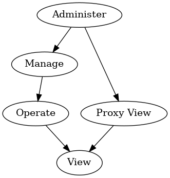
Individual clusters SHALL define whether attributes are readable, writable, or both readable and writable. Clusters also SHALL define which privilege is minimally required to be able to perform a particular read or write action on those attributes, or invoke particular commands. Device type specifications MAY further restrict the privilege required.
The Access Control Cluster SHALL require the Administer privilege to observe and modify the Access Control Cluster itself. The Administer privilege SHALL NOT be used on Access Control Entries which use the Group auth mode.
AuthMode
The AuthMode field SHALL specify the authentication mode required by this Access Control Entry.
| Value | Name | Description |
|---|---|---|
1 |
PASE |
|
2 |
CASE |
|
3 |
Group |
Subjects
The subjects field SHALL specify a list of Subject IDs, to which this Access Control Entry grants access.
Device types MAY impose additional constraints on the minimum number of subjects per Access Control Entry.
An attempt to create an entry with more subjects than the node can support SHALL result in a RESOURCE_EXHAUSTED error and the entry SHALL NOT be created.
Subject ID SHALL be of type uint64 with semantics depending on the entry’s AuthMode as follows:
| AuthMode | Subject |
|---|---|
PASE |
Lower 16-bits → Passcode ID |
CASE |
64-bits → Node ID or CASE Authenticated Tag |
Group |
Lower 16-bits → Group ID |
An empty subjects list indicates a wildcard; that is, this entry SHALL grant access to any Node that successfully authenticates via AuthMode. The subjects list SHALL NOT be empty if the entry’s AuthMode is PASE.
The PASE AuthMode is reserved for future use (see Section 6.6.2.8, “Bootstrapping of the Access Control Cluster”). An attempt to write an entry with AuthMode set to PASE SHALL fail with a status code of CONSTRAINT_ERROR.
For PASE authentication, the Passcode ID identifies the required passcode verifier, and SHALL be 0 for the default commissioning passcode.
For CASE authentication, the Subject ID is a distinguished name within the Operational Certificate shared during CASE session establishment, the type of which is determined by its range to be one of:
-
a Node ID, which identifies the required source node directly (by ID)
-
a CASE Authenticated Tag, which identifies the required source node indirectly (by tag)
For Group authentication, the Group ID identifies the required group, as defined in the Group Key Management Cluster.
Targets
The targets field SHALL specify a list of TargetStruct, which define the clusters on this Node to which this Access Control Entry grants access.
Device types MAY impose additional constraints on the minimum number of targets per Access Control Entry.
An attempt to create an entry with more targets than the node can support SHALL result in a RESOURCE_EXHAUSTED error and the entry SHALL NOT be created.
| ID | Name | Type | Constraint | Quality | Access | Default | Conformance |
|---|---|---|---|---|---|---|---|
0 |
Cluster |
cluster-id |
all |
X |
M |
||
1 |
Endpoint |
endpoint-no |
all |
X |
M |
||
2 |
DeviceType |
devtype-id |
all |
X |
M |
A single target SHALL contain at least one field (Cluster, Endpoint, or DeviceType), and SHALL NOT contain both an Endpoint field and a DeviceType field.
A target grants access based on the presence of fields as follows:
| Cluster | Endpoint | DeviceType | Target |
|---|---|---|---|
Invalid |
|||
D |
All clusters on any endpoint with Descriptor containing device type D |
||
E |
All clusters on only endpoint E |
||
E |
D |
Invalid |
|
C |
Only cluster C on all endpoints |
||
C |
D |
Only cluster C on any endpoint with Descriptor containing device type D |
|
C |
E |
Only cluster C on only endpoint E |
|
C |
E |
D |
Invalid |
An empty targets list indicates a wildcard: that is, this entry SHALL grant access to all cluster instances on all endpoints on this Node.
9.10.5.4. Extension Attribute
If present, the Access Control Extensions MAY be used by Administrators to store arbitrary data related to fabric’s Access Control Entries.
The Access Control Extension list SHALL support a single extension entry per supported fabric.
| Access Quality: Fabric Scoped | |||||||
|---|---|---|---|---|---|---|---|
ID |
Name |
Type |
Constraint |
Quality |
Access |
Default |
Conformance |
1 |
Data |
max 128 |
S |
M |
|||
Data
This field MAY be used by manufacturers to store arbitrary TLV-encoded data related to a fabric’s Access Control Entries.
The contents SHALL consist of a top-level anonymous list; each list element SHALL include a profile-specific tag encoded in fully-qualified form.
Administrators MAY iterate over this list of elements, and interpret selected elements at their discretion. The content of each element is not specified, but MAY be coordinated among manufacturers at their discretion.
9.10.5.5. SubjectsPerAccessControlEntry Attribute
This attribute SHALL provide the minimum number of Subjects per entry that are supported by this server.
Since reducing this value over time may invalidate ACL entries already written, this value SHALL NOT decrease across time as software updates occur that could impact this value. If this is a concern for a given implementation, it is recommended to only use the minimum value required and avoid reporting a higher value than the required minimum.
9.10.5.6. TargetsPerAccessControlEntry Attribute
This attribute SHALL provide the minimum number of Targets per entry that are supported by this server.
Since reducing this value over time may invalidate ACL entries already written, this value SHALL NOT decrease across time as software updates occur that could impact this value. If this is a concern for a given implementation, it is recommended to only use the minimum value required and avoid reporting a higher value than the required minimum.
9.10.5.7. AccessControlEntriesPerFabric Attribute
This attribute SHALL provide the minimum number of ACL Entries per fabric that are supported by this server.
Since reducing this value over time may invalidate ACL entries already written, this value SHALL NOT decrease across time as software updates occur that could impact this value. If this is a concern for a given implementation, it is recommended to only use the minimum value required and avoid reporting a higher value than the required minimum.
9.10.6. Error handling
Administrators SHALL use regular actions to administer the Access Control Cluster (by reading and writing entries in the list). Administrators SHOULD take care to use DataVersion conditional writes when administering the list or its contents.
The Access Control Cluster SHALL fail to write, and return an appropriate error, if an attempt is made to create or update an Access Control Entry or Access Control Extension such that it would have invalid contents.
For example, the following Access Control Entry conditions will result in an error of CONSTRAINT_ERROR:
-
Privilege enum value invalid
-
AuthMode enum value invalid
-
AuthMode is PASE (reserved for future use)
-
Subjects element invalid
-
e.g. illegal CAT with CASE AuthMode
-
-
Targets element invalid
-
e.g. no field present
-
e.g. both Endpoint and DeviceType fields present
-
-
Field combinations invalid
-
e.g. Administer Privilege with Group AuthMode
-
For example, the following Access Control Extension conditions will result in an error of CONSTRAINT_ERROR:
-
There is an attempt to add more than 1 entry associated with the given accessing fabric index in the extension list
-
Data value exceeds max length
-
Data value not valid TLV-encoded data
The Access Control Cluster MAY fail to write, and return a RESOURCE_EXHAUSTED error, if an attempt is made to create or update an entry or extension such that storage is exhausted.
9.10.7. Events
This cluster SHALL support these events:
| Id | Name | Priority | Access | Conformance |
|---|---|---|---|---|
0 |
AccessControlEntryChanged |
INFO |
S A |
M |
1 |
AccessControlExtensionChanged |
INFO |
S A |
M |
9.10.7.1. AccessControlEntryChanged Event
The cluster SHALL send AccessControlEntryChanged events whenever its ACL attribute data is changed by an Administrator.
-
Each added entry SHALL generate an event with ChangeType
Added. -
Each changed entry SHALL generate an event with ChangeType
Changed. -
Each removed entry SHALL generate an event with ChangeType
Removed.
| Access Quality: Fabric-Sensitive | ||||||
|---|---|---|---|---|---|---|
Id |
Field |
Type |
Constraint |
Quality |
Default |
Conformance |
1 |
AdminNodeID |
node-id |
desc |
X |
M |
|
2 |
AdminPasscodeID |
uint16 |
desc |
X |
M |
|
3 |
ChangeType |
all |
M |
|||
4 |
LatestValue |
all |
X |
M |
||
AdminNodeID
The Node ID of the Administrator that made the change, if the change occurred via a CASE session.
Exactly one of AdminNodeID and AdminPasscodeID SHALL be set, depending on whether the change occurred via a CASE or PASE session; the other SHALL be null.
AdminPasscodeID
The Passcode ID of the Administrator that made the change, if the change occurred via a PASE session. Non-zero values are reserved for future use (see PasscodeId generation in PBKDFParamRequest).
Exactly one of AdminNodeID and AdminPasscodeID SHALL be set, depending on whether the change occurred via a CASE or PASE session; the other SHALL be null.
ChangeType
The type of change as appropriate.
LatestValue
The latest value of the changed entry.
This field SHOULD be set if resources are adequate for it; otherwise it SHALL be set to NULL if resources are scarce.
9.10.7.2. AccessControlExtensionChanged Event
The cluster SHALL send AccessControlExtensionChanged events whenever its extension attribute data is changed by an Administrator.
-
Each added extension SHALL generate an event with ChangeType
Added. -
Each changed extension SHALL generate an event with ChangeType
Changed. -
Each removed extension SHALL generate an event with ChangeType
Removed.
| Access Quality: Fabric-Sensitive | ||||||
|---|---|---|---|---|---|---|
Id |
Field |
Type |
Constraint |
Quality |
Default |
Conformance |
1 |
AdminNodeID |
node-id |
desc |
X |
M |
|
2 |
AdminPasscodeID |
uint16 |
desc |
X |
M |
|
3 |
ChangeType |
all |
M |
|||
4 |
LatestValue |
all |
X |
M |
||
AdminNodeID
The Node ID of the Administrator that made the change, if the change occurred via a CASE session.
Exactly one of AdminNodeID and AdminPasscodeID SHALL be set, depending on whether the change occurred via a CASE or PASE session; the other SHALL be null.
AdminPasscodeID
The Passcode ID of the Administrator that made the change, if the change occurred via a PASE session. Non-zero values are reserved for future use (see PasscodeId generation in PBKDFParamRequest).
Exactly one of AdminNodeID and AdminPasscodeID SHALL be set, depending on whether the change occurred via a CASE or PASE session; the other SHALL be null.
ChangeType
The type of change as appropriate.
LatestValue
The latest value of the changed extension.
This field SHOULD be set if resources are adequate for it; otherwise it SHALL be set to NULL if resources are scarce.
9.11. Group Relationship
A group is a collection of one or more endpoints on one or more nodes. A group is identified by a unique group ID. If the network supports fabrics, each group, its group ID, and nodes that are members of the group, are all scoped to a single fabric.
Conceptually, there is a Group Table on each node that represents endpoint group membership. Each Group Table entry maps a group ID to one or more endpoints on that node, and any endpoint on a node MAY be assigned to one or more groups.
A group relationship, that is contained in the Group Table, is managed through the endpoints using the Groups cluster.
The Interaction Model allows a group identifier to be used as the destination of a message or action. If a message received by a node has a group destination, the Group Table is checked to see which endpoints on the node are members of the group. Then, the message will be delivered to those endpoints.
Note that there is a risk that multiple clients allocate the same group identifier for their own purpose. This likely leads to undesired behavior. For this reason, a client SHOULD discover the uniqueness of their 'candidate' group ID.
Also note that groupcast relies on its support by the underlying network layer. Depending on this network layer, groupcast may not work to "sleepy" devices that have their radio turned off when idle to preserve battery lifetime.
9.12. Bridge for non-Matter devices
9.12.1. Introduction
A Bridge serves to allow the use of non-Matter IoT devices (e.g. devices on a Zigbee or Z-Wave network, or any other non-Matter connectivity technology) in a Matter Fabric, with the goal to enable the consumer to keep using these non-Matter devices together with their Matter devices.
This is illustrated in the figure below: the non-Matter devices are exposed as Bridged Devices to Nodes on the Fabric. The Matter Nodes can communicate with both the (native) Matter devices as well as the Bridged Devices (by virtue of the Bridge which performs the translation between Matter and the other protocol).

|
Note
|
The bridging-concept described here is NOT intended to be used to expose Matter Nodes (which are not on the Fabric) to a Fabric, since direct connection of those Matter Nodes to the Fabric would provide a better experience. |
This section will describe how the Data Model concepts can be used by a Bridge to expose the Bridged Devices in such a way that they can be discovered and used by Nodes on the Matter Fabric.
9.12.2. Exposing functionality and metadata of Bridged Devices
After Commissioning, the Bridge SHALL expose (at least) one Node to the Fabric. The device implementing the Bridge MAY have more than one Node. This, however, is orthogonal to the bridging concept and will not be discussed further here.
-
On this Node, the Bridge SHALL expose a set of endpoints representing the various Bridged Devices on the non-Matter side of the Bridge.
-
Additionally, it SHALL expose an endpoint with the device type
Aggregatorwhich has aDescriptorcluster with aPartsListattribute containing all the endpoints representing those Bridged Devices. See Endpoint Composition for the concept of hierarchical composition. -
Each Bridged Device corresponds to an endpoint listed in this PartsList (see examples below). The
Descriptorcluster on the corresponding endpoint provides information about the particular Bridged Device, such as its device type(s).

In case the Bridge is bridging to/from multiple technologies (or has some other logical distinction between groups of bridged devices), it MAY expose such groups as two or more such hierarchical trees each with their Aggregator device type (e.g. one for each technology, see figure below); it MAY also combine all bridged devices in one hierarchical tree (see figure above). Both figures have the same set of bridged devices - the difference is in how the bridge manufacturer decides to expose them as one or multiple sets.

9.12.2.1. Topology or logical grouping
A Bridge typically has information on topology or logical grouping of the Bridged Devices, which can be of use to Nodes on the Matter Fabric.
-
For example, consider a Bridge with 50 lights. If this exposure of grouping, and their naming, would not be present, the user would just see a flat list of 50 lights on their controller and would not know which of those physical lights would be in which location/group.
If a Bridge has such information on topology or logical grouping, it SHOULD expose such information in the EndpointLists attribute of an Actions cluster (the ActionLists of which MAY be empty if no actions are exposed). A Bridge MAY make it possible (e.g., through a Bridge Manufacturer’s app) for its users to restrict whether all or some of such information is exposed to the Fabric. The Node on the Fabric using the Bridged Devices which is interested in using such topology or logical grouping (e.g. to show the grouping of lights per room in an overview to the user), SHOULD derive such grouping (and associated naming) from this EndpointLists attribute.
In the example below, the devices are split over two rooms, as exposed in the EndpointLists attribute.
This example also illustrates a composed endpoint for a composed Bridged Device, in this case a lighting device (Bridged Device at EP 24,25,26) which has an up- and downlighter which can be controlled separately, and which have their own set of lighting-related clusters on an individual endpoint (EP 25,26). Note that the Bridged Device Basic Information cluster is at the top of the hierarchy for this composed device (EP 24), while the application device types and application clusters are at the leaf endpoints (EP 25,26).
Since EP 25,26 are listed in the PartsList of EP 24, they 'inherit' the Bridged Node device type and information in the Bridged Device Basic Information cluster of EP 24.


9.12.2.2. Native Matter functionality in Bridge
The Bridge MAY also contain native Matter functionality, i.e. non-bridged functionality, such as in the example below, which shows a smart speaker device having, in addition to a Wi-Fi connection, also a Zigbee connection towards a number of Zigbee lights. The speaker functionality (EP 31) is native Matter functionality (and could have a Controller role to allow sending Matter commands upon receiving voice commands), while the remainder of the non-zero endpoints represent the Bridged Devices.

9.12.2.3. Information about Bridged Devices
For each Bridged Device, the Bridge SHALL include a Bridged Device Basic Information cluster on the endpoint which represents this Bridged Device.
Furthermore, the Bridge SHALL include a Descriptor cluster with
-
a DeviceTypeList attribute containing device type Bridged Node plus the device type(s) of the Bridged Device, and
-
a
PartsListattribute listing any other endpoints which jointly expose the functionality of this Bridged Device.
In case a Bridged Device is represented by multiple endpoints, the Bridged Device Basic Information and Descriptor clusters SHALL only be present on the endpoint which is the top level of the hierarchy representing this Bridged Device (example: endpoint 24 in Figure 43, “example of endpoints representing Bridged Devices using grouping”).
In case the Bridged Device contains a power source such as battery or mains power feed, and information about the state of that power source is available to the Bridge, the Bridge SHALL also include a Power Source Configuration cluster and a Power Source cluster on the endpoint representing the Bridged Device. An example of this is shown for the battery-powered temperature sensor on endpoint 23 in Figure 43, “example of endpoints representing Bridged Devices using grouping”.
Two special cases:
-
In case such Bridged Device is represented by multiple endpoints, and the Bridged Device contains only one power source, the
Power Source Configurationcluster SHALL be present on the endpoint which is the top level of the hierarchy representing this Bridged Device, while thePower Sourcecluster SHALL be present on the endpoint which corresponds to the part of the Bridged Device containing the power source. -
In case a Bridged Device contains multiple power sources, each of these power sources SHALL be represented by a
Power Sourcecluster on the endpoint which corresponds to the part of the Bridged Device containing the power source (no more than one such cluster per endpoint). ThePower Source Configurationcluster SHALL be present on the endpoint which is the top level of the hierarchy representing this Bridged Device, referencing the endpoints where thePower Sourceclusters for this Bridged Device are present.
In case a Bridged Device does not contain a power source such as battery or mains power feed, or information about the state of that power source is not available to the Bridge, the Bridge SHALL NOT include a Power Source Configuration cluster and a Power Source cluster on the endpoint representing the Bridged Device.
9.12.2.4. Clusters for Bridged Device functionality (device types)
For each Bridged Device, the Bridge SHALL expose the clusters required for a device of the indicated Matter device type(s).
This allows the Matter Nodes to recognize the device type of the Bridged Device and interact with its clusters in the same manner as with a native Matter Node of that device type.
9.12.3. Discovery of Bridged Devices
A Node which discovers another Node with device type Aggregator on one of its endpoints SHOULD walk the entire tree of endpoints via the PartsList attributes and endpoints to discover the list of Bridged Devices,
including their device types and other attributes, as well as any native Matter functionality potentially present on the Node.
Each endpoint found containing a Bridged Node device type represents a Bridged Device of the device type(s) specified at this endpoint, or one of the endpoints found via its PartsList. If the discovering Node supports this device type, it MAY add this Bridged Device to the list of devices which it could interact with, or could set up configuration for.
This discovering Node SHALL use the acquired information on the available Bridged Devices to set up (configure) (likely with input from the user) how the Bridged Devices can be used with the Matter Nodes (e.g. which switch controls which light, or how to control a light from an app on the user’s phone).
Since the Bridge may expose a large number of Bridged Devices, the discovering Node SHALL use the NodeLabel attribute in the Bridged Device Basic Information cluster of each of the Bridged Devices to allow the user to easily identify and recognize the various Bridged Devices, and expedite the setup/configuration process, rather than present the user with an unannotated list of, for example, 20 lights, 3 sensors and 4 switches. These labels have likely been populated by the user when interacting previously with the Bridge e.g. through means provided by the Bridge Manufacturer, such as a Bridge Manufacturer app.
If power source-related information regarding the Bridged Device is provided in the Power Source cluster on the associated endpoint, the discovering Node SHOULD use this information in a similar manner as power source-related information acquired from a Matter Node’s Power Source cluster. Such information can then be used to inform the user about the state of the power source (e.g. warn about low batteries) in a Bridged Device in a similar manner as done for Matter Nodes.
9.12.4. Configuration of Bridged Devices
For configuration of the discovered Bridged Devices, two basic archetypes are described in the following sections: one for actuators and one for sensors/switches.
Since a Bridged Device of a certain device type has the same set of application clusters as a native Matter device of the same device type, this process is similar to configuring a native Matter device of that device type.
9.12.4.1. Sending commands from a Matter controller to a Bridged Device
For Bridged Devices that are actuators and hence have a Controlee role, a Controller Node on the Fabric MAY send commands to the associated clusters on one or more endpoints on the Bridge’s Node, such as an On command to the On/Off cluster of a Bridged Device. The Bridge SHALL forward this command to the relevant Bridged Device after conversion between the Matter protocol and the non-Matter device’s native protocol.
Example:
A Controller creates a Group containing some Matter lights as well as some non-Matter lights, by sending an Add Group command to the instances of the Group cluster on both the endpoints of the Matter lights as well as on the Bridge’s Node endpoints representing the targeted bridged lights.
Similarly, the Controller creates one or more Scenes using the instances of the Scene cluster on these endpoints.
The Controller then sends a (single) On command (On/Off cluster) to this group to switch on all these lights in a single operation. This (single) multicast message will be received (and interpreted) by the Matter lights which are part of this group as well as by the Bridge, which will forward it (after appropriate protocol conversion) to the relevant bridged lights.
Similarly, the Controller sends a (single) Move to Level (Level Control cluster) or sends a (single) Recall Scene (Scene cluster) to this group, to set the brightness resp. recall a scene contents on all these lights in a single operation.

9.12.4.2. Receiving status/events/commands from a Bridged Device
For Bridged Devices like sensors and switches, the Bridge will receive value updates (e.g. Zigbee attribute reports), events and/or commands from those devices, and SHALL (after conversion from the native protocol of the non-Matter devices towards Matter protocol) represent those as attributes, events and/or commands in the appropriate clusters on the associated endpoints of the Bridge.
Interactions with those attributes/events/commands on the Matter side (e.g., towards a Controller using the sensor/switch data) SHOULD be identical to interactions with corresponding attributes/events/commands in native Matter sensors and switches (e.g., attribute readout and subscription, proxying and eventing).
Examples:
-
A temperature sensor sends a status report to the Bridge over a non-Matter interface. The logic in the Bridge processes this as an update to the
Measured Valueattribute of theTemperature Measurementcluster on the endpoint associated with this bridged sensor.
Nodes on the Fabric which have an interest in this value can read the updated attribute value, and can configure a subscription on this attribute. This is identical to reading an attribute value or setting up an attribute subscription on a native-Matter temperature sensor Node. -
A user presses a button on a (push-button) switch device. The switch device sends a message to the Bridge over a non-Matter interface. The logic in the Bridge processes this to generate an
InitialPressevent (Switchcluster) on the endpoint representing the switch.
Nodes on the Fabric which have an interest in the switch operation can setup eventing from this cluster.

9.12.5. New features for Bridged Devices
Bridged Devices can have their software updated independently of the Bridge, through Bridge Manufacturer-specific means. These updates MAY result in one or more changes to their capabilities, such as supported clusters and/or attributes, for an endpoint. Like every Matter Node, every endpoint on the Bridge’s Node contains a Descriptor cluster that contains attributes for the device types, endpoints (PartsList) and supported clusters. Nodes that wish to be notified of such changes SHOULD monitor changes of these attributes.
9.12.6. Changes to the set of Bridged Devices
Bridged Devices can be added to or removed from the Bridge through Bridge-specific means. For example, the user can use a Manufacturer-provided app to add/remove Zigbee devices to/from their Matter-Zigbee Bridge.
When an update to the set of Bridged Devices (which are exposed according to the Section 9.12.11, “Best practices for Bridge Manufacturers”) occurs, the Bridge SHALL
-
on the
Descriptorclusters of the root node endpoint and of the endpoint which holds theAggregatordevice type: update thePartsListattribute (add/remove entries from this list) -
update the exposed endpoints and their descriptors according to the new set of Bridged Devices
Nodes that wish to be notified of added/removed devices SHOULD monitor changes of the PartsList attribute in the Descriptor cluster on the root node endpoint and the endpoint which holds the Aggregator device type.
Allocation of endpoints for Bridged Devices SHALL be performed as described in Dynamic Endpoint allocation.
9.12.7. Changes to device names and grouping of Bridged Devices
Typically, the user has some means (e.g. a Manufacturer-provided app) to assign names to the Bridged Devices, or names could be assigned automatically by the Bridge. The Bridge SHALL expose such names in the NodeLabel attribute of the Bridged Device Basic Information cluster on the applicable endpoint.
Similarly, the user typically has some means to group the Bridged Devices (e.g. via a room/zone-concept) and provide names to such groups, or grouping could be applied automatically by the Bridge. The Bridge SHOULD expose such grouping using the EndpointLists attribute of the Actions cluster as described above.
For such exposed information, when there is a change in naming/grouping (e.g. the user makes changes via a Manufacturer-provided app), the Bridge SHALL update the appropriate attributes.
Nodes that wish to be notified of a change in such a name or grouping SHOULD monitor changes of this attribute or cluster.
9.12.8. Setup flow for a Bridge (plus Bridged Devices)
As described above, the Bridge together with its Bridged Devices is exposed as a single Node with a list of endpoints. Consequently, a single Node ID and a single Operational Certificate is assigned during Commissioning and a single pass through the commissioning flow is required to bring the Bridge (along with its Bridged Devices) onto a Fabric. This provides for a simple user experience, since the user only needs to go through the commissioning flow for the Bridge, and not separately for each of the Bridged Devices.
9.12.9. Access Control
The Bridge is a Matter node, therefore it has a single Access Control Cluster for the entire Node, like every other Matter Node. This cluster contains all Access Control Entries for each of its endpoints, including for all Bridged Devices and other native Matter functionality exposed by the Bridge Node.
A typical setup of Access Control would reflect which privilege level a Matter Controller needs to have for one or more Bridged Devices. This overall access set may be a subset of all the Bridged Devices on the Bridge, rather than all endpoints on a Bridge. This can be accomplished by setting an Access Control Entry containing as targets a list of those endpoints representing a Bridged Device or a set of Bridged Devices. As defined in the ACL model, it is also possible to specify access towards specific Targets, for example all Bridged Devices of device type Extended Color Light.
9.12.10. Software update (OTA)
The Bridge is a Matter device and its Matter-related functionality MAY be updated using the mechanism described in Section 11.19, “Over-the-Air (OTA) Software Update”.
The Bridged Devices, on the other hand, are not native Matter devices, do not have a Product ID, and are not listed in the Distributed Compliance Ledger. They are typically updated using a mechanism defined and deployed by the Bridge Manufacturer. That same mechanism is typically used to update the parts of the Bridge which are not related to Matter, which is particularly relevant to allow synchronization of updates to the non-Matter part of the Bridge with updates to the Bridged Devices. Obviously, such mechanism MAY also be employed to update the entire Bridge firmware, including the Matter-related functionality.
9.12.11. Best practices for Bridge Manufacturers
This section summarizes (in order of priority) the process to determine which non-Matter devices the Bridge exposes to the Fabric.
-
Choice of supported device types
-
A Manufacturer MAY choose which of the Matter device types they can or want to support in the Bridge. After implementation of support for bridging of those device types, they SHALL certify the Bridge for those device types.
-
By default, a Bridge SHOULD expose to the Fabric all its connected non-Matter devices which can be mapped to a Matter device type for which that Bridge is certified.
E.g., if a Bridge is certified for Matter light bulbs, it SHOULD NOT hide any light bulb on the non-Matter side from the Fabric by default (some situations where the Bridge MAY deviate from this recommendation are in the following text). -
Given the wide variety of device types on a wide variety of standards, there may be device types on the non-Matter side that do not have a corresponding Matter device type. Such devices cannot be bridged to a Matter device type. The Manufacturer MAY choose to not expose such devices with the Bridge or MAY expose them with a manufacturer-specific device type and/or manufacturer-specific clusters.
-
-
Compatibility issues
-
For the device types for which a Bridge is certified, a Bridge Manufacturer MAY decide to not expose certain devices based on any reason, including compatibility and interoperability reasons, or to expose them in a 'best-effort' manner as needed.
-
The Bridge Manufacturer may choose to not expose a device that does not support certain functions or features which are mandatory for a Matter device type, but which are defined as optional, or not defined at all, in the specification for the corresponding device type on the non-Matter side of the bridge. Such a Bridge would expose to the Fabric only Bridged Devices of device types which support those particular control functions or features which are required.
-
The Bridge Manufacturer may also choose to map or emulate such features which are not available in the Bridged Device; example: for a bridged colored light connected via a protocol which does not support scenes, the Bridge could emulate the scene function by storing the scenes in the Bridge and sending corresponding brightness and color commands to the light when a Scene Recall command is received from a Matter Node.
-
-
-
User choice
-
A Bridge MAY make it possible (e.g., through a Bridge Manufacturer’s app) for its users to further restrict which devices are exposed to the Fabric.
For example, a user may decide to prevent exposure to the Fabric of certain Devices Types, such as all occupancy sensors, or of only certain devices of a certain device type, such as only their bedroom occupancy sensor.
-
9.12.12. Best practices for Administrators
An Administrator MAY indicate to users which devices are native Matter and which ones are Bridged Devices, as determined using the presence of a Bridged Node device type on the endpoint, in order to ensure the user does not make assumptions about the Bridged Devices having the same security requirements as native Matter devices.
9.13. Bridged Device Basic Information Cluster
9.13.1. Scope & Purpose
This Cluster serves two purposes towards a Node communicating with a Bridge:
-
indicate that the functionality on the Endpoint where it is placed (and its Parts) is bridged from a non-Matter technology, and
-
provide a centralized collection of attributes that the Node MAY collect to aid in conveying information regarding the Bridged Device to a user, such as the vendor name, the model name, or user-assigned name.
This cluster SHALL be exposed by a Bridge on the Endpoint representing each Bridged Device. When the functionality of a Bridged Device is represented using a set of Endpoints, this cluster SHALL only be exposed on the Endpoint which is at the top of the hierarchy for the functionality of that Bridged Device.
This cluster SHALL NOT be used on an endpoint that is not in the Descriptor cluster PartsList of an endpoint with an Aggregator device type.
This cluster has been derived from the Basic Information Cluster, and provides generic information about the Bridged Device. Not all of the attributes in the Basic Information Cluster are relevant for a Bridged Device (e.g. ProductID since it is not a Matter Device). For other attributes, the information which is listed as Mandatory for the Basic Information Cluster, may not be available when the Bridged Device does not provide it to the Bridge, and the Bridge has no other means to determine it. For such cases where the information for a particular attribute is not available, the Bridge SHOULD NOT include the attribute in the cluster for this Bridged Device. See below for Conformance details.
9.13.2. Revision History
-
The global ClusterRevision attribute value SHALL be the highest revision number in the table below.
| Revision | Description |
|---|---|
1 |
Initial Release |
9.13.3. Classification
| Hierarchy | Role | Context | PICS Code |
|---|---|---|---|
Derived from Basic Information |
Utility |
Endpoint |
BRBINFO |
9.13.6. Attributes
| Name | Conformance |
|---|---|
DataModelRevision |
X |
VendorName |
O |
VendorID |
O |
ProductName |
O |
ProductID |
X |
NodeLabel |
O |
Location |
X |
HardwareVersion |
O |
HardwareVersionString |
O |
SoftwareVersion |
O |
SoftwareVersionString |
O |
ManufacturingDate |
O |
PartNumber |
O |
ProductURL |
O |
ProductLabel |
O |
SerialNumber |
O |
LocalConfigDisabled |
X |
Reachable |
M |
UniqueID |
O |
CapabilityMinima |
X |
Since this cluster has been derived from the Basic Information Cluster, the identifiers of the attributes, their range, quality and default characteristics and their descriptions correspond to those in that Cluster and those descriptions are not repeated here. Several attributes from the Basic Information Cluster which are not relevant or applicable for a Bridged Device have been marked with X in column Conformance and SHALL NOT be used in the Bridged Device Basic Information Cluster.
The Conformance characteristics of several attributes in this cluster have changed from M to O compared to their Conformance in the Basic Information Cluster, and SHALL be used according to the table above.
The Bridge SHOULD fill these attributes with the available information, which could e.g. come from the Bridged Device provided to the Bridge over the non-Matter interface (e.g. VendorName and VendorID) or could have been provided by the user (e.g. assigned name of a device for NodeLabel).
If the manufacturer of a Bridged Device is known to the Bridge, the Bridge SHALL provide this name (in attribute VendorName), otherwise it SHALL NOT include this attribute.
If the manufacturer of a Bridged Device and the associated Alliance-assigned Vendor ID are known to the Bridge (e.g. by copying the Manufacturer Code from the Node Descriptor of a Zigbee device), the Bridge SHALL provide this identifier (in attribute VendorID), otherwise it SHALL NOT include this attribute.
The Reachable attribute SHALL be used to indicate whether the bridged device is reachable by the bridge over the non-Matter network, so a Matter Node which wants to communicate with a bridged device can get an indication that this might fail (when the attribute is False). Determination of reachability MAY not be perfect (e.g. depending on technology employed), so the Matter Node SHOULD be aware of the risk of false positives and negatives on reachability determination. For example, a bridged device MAY be marked as unreachable while it could actually be reached, and vice-versa.
Also see event ReachableChanged below.
The UniqueID attribute (when present) for a Bridged Device SHOULD be updated when the Bridge is factory reset.
9.13.7. Events
This cluster SHALL support these events:
| Name | Conformance |
|---|---|
StartUp |
O |
ShutDown |
O |
Leave |
O |
ReachableChanged |
M |
9.13.7.1. ReachableChanged Event
This event SHALL be generated when there is a change in the Reachable attribute. Its purpose is to provide an indication towards interested parties that the reachability of a bridged device (over the non-Matter network) has changed, so they MAY take appropriate action.
After (re)start of a bridge this event MAY be generated.
9.14. Actions Cluster
9.14.1. Scope & Purpose
This cluster provides a standardized way for a Node (typically a Bridge, but could be any Node) to expose
-
information about logical grouping of endpoints on the Node (example: lights in a room)
-
information about named actions that can be performed on such a group of endpoints (example: recall a scene for a group of lights by its name)
-
commands to trigger such actions
-
events to receive feedback on the state of such actions.
The information on grouping and available actions is typically provided by the user or Bridge manufacturer via some means not defined in Matter, and therefore provided as read-only to Nodes. For example: a manufacturer-provided app allows a user to set up logical grouping and create/assign scene for such groups.
Using this cluster, a Node can learn about such logical grouping, provided actions, and trigger such actions.
While the origin of this cluster stems from use cases with a Bridge, its server side may also be implemented on any Node which can expose certain grouping, actions or automations to other users.
After defining the attributes, commands and events for this cluster, and the associated data types, several examples are provided to illustrate the capabilities of this cluster.
Actions can be defined in a flexible manner to suit the needs of the various nodes implementing this cluster. For each action, the commands available for that particular action are defined.
This cluster can be used to expose only the grouping of endpoints without any actions defined by populating the EndpointList attribute accordingly and providing an empty list for ActionList.
The term 'action' in the description of this cluster should not be confused with the term 'action' as used in the Interaction Model.
9.14.2. Revision History
The global ClusterRevision attribute value SHALL be the highest revision number in the table below.
| Revision | Description |
|---|---|
1 |
Initial Release |
9.14.6. Attributes
| ID | Name | Type | Constraint | Quality | Default | Access | Conformance |
|---|---|---|---|---|---|---|---|
0x0000 |
ActionList |
list[ActionStruct] |
max 256 |
empty |
R V |
M |
|
0x0001 |
EndpointLists |
list[EndpointListStruct] |
max 256 |
empty |
R V |
M |
|
0x0002 |
SetupURL |
max 512 |
empty |
R V |
O |
9.14.6.1. ActionList attribute
The ActionList attribute holds the list of actions. Each entry SHALL have an unique ActionID, and its EndpointListID SHALL exist in the EndpointLists attribute.
9.14.6.2. EndpointLists attribute
The EndpointLists attribute holds the list of endpoint lists. Each entry SHALL have an unique EndpointListID.
9.14.6.3. SetupURL attribute
The SetupURL attribute (when provided) SHALL indicate a URL; its syntax SHALL follow the syntax as specified in RFC 3986, max. 512 ASCII characters. The location referenced by this URL SHALL provide additional information for the actions provided:
-
When used without suffix, it SHALL provide information about the various actions which the cluster provides.
-
Example: SetupURL could take the value of example://Actions or https://www.example.com/Matter/bridgev1/Actions for this generic case (access generic info how to use actions provided by this cluster).
-
-
When used with a suffix of "/?a=" and the decimal value of ActionID for one of the actions, it MAY provide information about that particular action. This could be a deeplink to manufacturer-app/website (associated somehow to the server node) with the information/edit-screen for this action so that the user can view and update details of the action, e.g. edit the scene, or change the wake-up experience time period.
-
Example of SetupURL with suffix added: example://Actions/?a=12345 or https://www.example.com/Matter/bridgev1/Actions/?a=12345 for linking to specific info/editing of the action with ActionID 0x3039.
-
9.14.7. Commands
| ID | Name | Direction | Response | Access | Conformance |
|---|---|---|---|---|---|
0x00 |
InstantAction |
client ⇒ server |
Y |
O |
desc |
0x01 |
InstantActionWithTransition |
client ⇒ server |
Y |
O |
desc |
0x02 |
StartAction |
client ⇒ server |
Y |
O |
desc |
0x03 |
StartActionWithDuration |
client ⇒ server |
Y |
O |
desc |
0x04 |
StopAction |
client ⇒ server |
Y |
O |
desc |
0x05 |
PauseAction |
client ⇒ server |
Y |
O |
desc |
0x06 |
PauseActionWithDuration |
client ⇒ server |
Y |
O |
desc |
0x07 |
ResumeAction |
client ⇒ server |
Y |
O |
desc |
0x08 |
EnableAction |
client ⇒ server |
Y |
O |
desc |
0x09 |
EnableActionWithDuration |
client ⇒ server |
Y |
O |
desc |
0x0a |
DisableAction |
client ⇒ server |
Y |
O |
desc |
0x0b |
DisableActionWithDuration |
client ⇒ server |
Y |
O |
desc |
Conformance: a server SHALL support a command when it is listed in the SupportedCommands data field of one or more actions listed in the ActionList provided by the server.
Some general requirements and data fields for all the commands:
-
The ActionID data field SHALL indicate the action identifier. If there is no entry the in ActionList holding the same action identifier, a response shall be generated with the StatusCode NOT_FOUND.
-
The InvokeID data field MAY be provided by the client when invoking a command. When this value is provided, the server SHALL generate a StateChanged event when the action changes to a new state or an ActionFailed event when execution of the action fails; in the data of such events, the value of the InvokeID data field from the invoke will be provided, so that the client can relate the event back to the corresponding command. It is up to the client to determine which value is provided in InvokeID. When sending multiple commands for the same action, with different InvokeID, the server SHALL provide in the event the InvokeID value from the most recent command for a particular ActionID.
-
If the command refers to an action which currently is not in a state where the command applies, a response shall be generated with the StatusCode INVALID_COMMAND.
-
Actions are typically mapped to state changes of the involved endpoints. Those endpoints can also be controlled with commands from other clusters, controlled by other nodes and impacted by non-Matter interactions (e.g. local controls). Such other interactions can cause the state of the endpoints to differ from the results of the command which triggered the action. A client interested in such changes can use the InvokeID data field (see above) to receive events StateChanged and ActionFailed for feedback for such cases.
9.14.7.1. InstantAction Command
This command SHALL have the following data fields:
| ID | Name | Type | Constraint | Quality | Default | Conformance |
|---|---|---|---|---|---|---|
0 |
ActionID |
uint16 |
all |
M |
||
1 |
InvokeID |
uint32 |
all |
O |
This command triggers an action (state change) on the involved endpoints, in a "fire and forget" manner. Afterwards, the action’s state SHALL be Inactive.
Example: recall a scene on a number of lights.
9.14.7.2. InstantActionWithTransition Command
This command SHALL have the following data fields:
| ID | Name | Type | Constraint | Quality | Default | Conformance |
|---|---|---|---|---|---|---|
0 |
ActionID |
uint16 |
all |
M |
||
1 |
InvokeID |
uint32 |
all |
O |
||
2 |
TransitionTime |
uint16 |
all |
MS |
M |
The TransitionTime data field SHALL indicate the transition time in 1/10th of seconds. It is recommended that, where possible (e.g., it is not possible for attributes with Boolean data type), a gradual transition SHOULD take place from the old to the new state over this time period. However, the exact transition is manufacturer dependent.
This command triggers an action (state change) on the involved endpoints, with a specified time to transition from the current state to the new state. During the transition, the action’s state SHALL be Active. Afterwards, the action’s state SHALL be Inactive.
Example: recall a scene on a number of lights, with a specified transition time.
9.14.7.3. StartAction Command
This command SHALL have the following data fields:
| ID | Name | Type | Constraint | Quality | Default | Conformance |
|---|---|---|---|---|---|---|
0 |
ActionID |
uint16 |
all |
M |
||
1 |
InvokeID |
uint32 |
all |
O |
This command triggers the commencement of an action on the involved endpoints. Afterwards, the action’s state SHALL be Active.
Example: start a dynamic lighting pattern (such as gradually rotating the colors around the setpoints of the scene) on a set of lights.
Example: start a sequence of events such as a wake-up experience involving lights moving through several brightness/color combinations and the window covering gradually opening.
9.14.7.4. StartActionWithDuration Command
This command SHALL have the following data fields:
| ID | Name | Type | Constraint | Quality | Default | Conformance |
|---|---|---|---|---|---|---|
0 |
ActionID |
uint16 |
all |
M |
||
1 |
InvokeID |
uint32 |
all |
O |
||
2 |
Duration |
uint32 |
all |
MS |
M |
The Duration data field SHALL indicate the requested duration in seconds.
This command triggers the commencement of an action on the involved endpoints, and SHALL change the action’s state to Active. After the specified Duration, the action will stop, and the action’s state SHALL change to Inactive.
Example: start a dynamic lighting pattern (such as gradually rotating the colors around the setpoints of the scene) on a set of lights for 1 hour (Duration=3600).
9.14.7.5. StopAction Command
This command SHALL have the following data fields:
| ID | Name | Type | Constraint | Quality | Default | Conformance |
|---|---|---|---|---|---|---|
0 |
ActionID |
uint16 |
all |
M |
||
1 |
InvokeID |
uint32 |
all |
O |
This command stops the ongoing action on the involved endpoints. Afterwards, the action’s state SHALL be Inactive.
Example: stop a dynamic lighting pattern which was previously started with StartAction.
9.14.7.6. PauseAction Command
This command SHALL have the following data fields:
| ID | Name | Type | Constraint | Quality | Default | Conformance |
|---|---|---|---|---|---|---|
0 |
ActionID |
uint16 |
all |
M |
||
1 |
InvokeID |
uint32 |
all |
O |
This command pauses an ongoing action, and SHALL change the action’s state to Paused.
Example: pause a dynamic lighting effect (the lights stay at their current color) which was previously started with StartAction.
9.14.7.7. PauseActionWithDuration Command
This command SHALL have the following data fields:
| ID | Name | Type | Constraint | Quality | Default | Conformance |
|---|---|---|---|---|---|---|
0 |
ActionID |
uint16 |
all |
M |
||
1 |
InvokeID |
uint32 |
all |
O |
||
2 |
Duration |
uint32 |
all |
MS |
M |
The Duration data field SHALL indicate the requested duration in seconds.
This command pauses an ongoing action, and SHALL change the action’s state to Paused. After the specified Duration, the ongoing action will be automatically resumed. which SHALL change the action’s state to Active.
Example: pause a dynamic lighting effect (the lights stay at their current color) for 10 minutes (Duration=600).
The difference between Pause/Resume and Disable/Enable is on the one hand semantic (the former is more of a transitionary nature while the latter is more permanent) and on the other hand these can be implemented slightly differently in the implementation of the action (e.g. a Pause would be automatically resumed after some hours or during a nightly reset, while an Disable would remain in effect until explicitly enabled again).
9.14.7.8. ResumeAction Command
This command SHALL have the following data fields:
| ID | Name | Type | Constraint | Quality | Default | Conformance |
|---|---|---|---|---|---|---|
0 |
ActionID |
uint16 |
all |
M |
||
1 |
InvokeID |
uint32 |
all |
O |
This command resumes a previously paused action, and SHALL change the action’s state to Active.
The difference between ResumeAction and StartAction is that ResumeAction will continue the action from the state where it was paused, while StartAction will start the action from the beginning.
Example: resume a dynamic lighting effect (the lights' colors will change gradually, continuing from the point they were paused).
9.14.7.9. EnableAction Command
This command SHALL have the following data fields:
| ID | Name | Type | Constraint | Quality | Default | Conformance |
|---|---|---|---|---|---|---|
0 |
ActionID |
uint16 |
all |
M |
||
1 |
InvokeID |
uint32 |
all |
O |
This command enables a certain action or automation. Afterwards, the action’s state SHALL be Active.
Example: enable a motion sensor to control the lights in an area.
9.14.7.10. EnableActionWithDuration Command
This command SHALL have the following data fields:
| ID | Name | Type | Constraint | Quality | Default | Conformance |
|---|---|---|---|---|---|---|
0 |
ActionID |
uint16 |
all |
M |
||
1 |
InvokeID |
uint32 |
all |
O |
||
2 |
Duration |
uint32 |
all |
MS |
M |
The Duration data field SHALL indicate the requested duration in seconds.
This command enables a certain action or automation, and SHALL change the action’s state to be Active. After the specified Duration, the action or automation will stop, and the action’s state SHALL change to Disabled.
Example: enable a "presence mimicking" behavior for the lights in your home during a vacation; the Duration field is used to indicated the length of your absence from home. After that period, the presence mimicking behavior will no longer control these lights.
9.14.7.11. DisableAction Command
This command SHALL have the following data fields:
| ID | Name | Type | Constraint | Quality | Default | Conformance |
|---|---|---|---|---|---|---|
0 |
ActionID |
uint16 |
all |
M |
||
1 |
InvokeID |
uint32 |
all |
O |
This command disables a certain action or automation, and SHALL change the action’s state to Inactive.
Example: disable a motion sensor to no longer control the lights in an area.
9.14.7.12. DisableActionWithDuration Command
This command SHALL have the following data fields:
| ID | Name | Type | Constraint | Quality | Default | Conformance |
|---|---|---|---|---|---|---|
0 |
ActionID |
uint16 |
all |
M |
||
1 |
InvokeID |
uint32 |
all |
O |
||
2 |
Duration |
uint32 |
all |
MS |
M |
The Duration data field SHALL indicate the requested duration in seconds.
This command disables a certain action or automation, and SHALL change the action’s state to Disabled. After the specified Duration, the action or automation will re-start, and the action’s state SHALL change to either Inactive or Active, depending on the actions (see examples 4 and 6).
Example: disable a "wakeup" experience for a period of 1 week when going on holiday (to prevent them from turning on in the morning while you’re not at home). After this period, the wakeup experience will control the lights as before.
9.14.8. Events
This cluster SHALL support these events:
| Id | Name | Priority | Access | Conformance |
|---|---|---|---|---|
0 |
StateChanged |
INFO |
V |
M |
1 |
ActionFailed |
INFO |
V |
M |
9.14.8.1. StateChanged Event
This event SHALL be generated when there is a change in the State of an ActionID during the execution of an action and the most recent command using that ActionID used an InvokeID data field.
It provides feedback to the client about the progress of the action.
This event SHALL have the following data fields:
| ID | Name | Type | Constraint | Quality | Default | Conformance |
|---|---|---|---|---|---|---|
0 |
ActionID |
uint16 |
M |
|||
1 |
InvokeID |
uint32 |
M |
|||
2 |
NewState |
M |
The ActionID data field SHALL be set to the ActionID of the action which has changed state.
The InvokeID data field SHALL be set to the InvokeID which was provided to the most recent command referencing this ActionID.
The NewState data field SHALL be set to state that the action has changed to.
Example: When InstantActionWithTransition is invoked (with an InvokeID data field), two StateChanged events will be generated:
-
one when the transition starts (NewState=Active)
-
one when the transition completed (NewState=Inactive)
9.14.8.2. ActionFailed Event
This event SHALL be generated when there is some error which prevents the action from its normal planned execution and the most recent command using that ActionID used an InvokeID data field.
It provides feedback to the client about the non-successful progress of the action.
This event SHALL have the following data fields:
| ID | Name | Type | Constraint | Quality | Default | Conformance |
|---|---|---|---|---|---|---|
0 |
ActionID |
uint16 |
M |
|||
1 |
InvokeID |
uint32 |
M |
|||
2 |
NewState |
M |
||||
3 |
Error |
M |
The ActionID data field SHALL be set to the ActionID of the action which encountered an error.
The InvokeID data field SHALL be set to the InvokeID which was provided to the most recent command referencing this ActionID.
The NewState data field SHALL be set to state that the action is in at the time of generating the event.
The Error data field SHALL be set to indicate the reason for non-successful progress of the action.
Example: When InstantActionWithTransition is invoked (with an InvokeID data field), and another controller changes the state of one or more of the involved endpoints during the transition, thus interrupting the transition triggered by the action, two events would be generated:
-
StateChanged when the transition starts (NewState=Active)
-
ActionFailed when the interrupting command occurs (NewState=Inactive, Error=interrupted)
Example: When InstantActionWithTransition is invoked (with an InvokeID data field = 1), and the same client invokes an InstantAction with (the same or another ActionId and) InvokeID = 2, and this second command interrupts the transition triggered by the first command, these events would be generated:
-
StateChanged (InvokeID=1, NewState=Active) when the transition starts
-
ActionFailed (InvokeID=2, NewState=Inactive, Error=interrupted) when the second command interrupts the transition
-
StateChanged (InvokeID=2, NewState=Inactive) upon the execution of the action for the second command
9.14.9. Data Types
9.14.9.1. ActionStruct
The ActionStruct data type holds the details of a single action, and contains the data fields below.
| ID | Name | Type | Constraint | Quality | Access | Default | Conformance |
|---|---|---|---|---|---|---|---|
0 |
ActionID |
uint16 |
all |
R |
M |
||
1 |
Name |
max 32 [128] |
R |
M |
|||
2 |
Type |
all |
R |
M |
|||
3 |
EndpointListID |
uint16 |
all |
R |
M |
||
4 |
SupportedCommands |
map16 |
0 to 0x0fff |
R |
M |
||
5 |
State |
all |
R |
M |
The ActionID data field SHALL provide an unique identifier used to identify an action.
The Name data field SHALL indicate the name (as assigned by the user or automatically by the server) associated with this action. This can be used for identifying the action to the user by the client. Example: "my colorful scene".
The Type data field SHALL indicate the type of action. The value of Type of an action, along with its SupportedCommands can be used by the client in its UX or logic to determine how to present or use such action. See ActionTypeEnum for details and examples.
The EndPointListID data field SHALL provide a reference to the associated endpoint list, which specifies the endpoints on this Node which will be impacted by this ActionID.
The SupportedCommands data field is a bitmap which SHALL be used to indicate which of the cluster’s commands are supported for this particular action, with a bit set to 1 for each supported command according to the table below. Other bits SHALL be set to 0.
Note - the bit allocation of this table SHALL follow the ID’s of the Commands of this cluster.
| bit | Command supported |
|---|---|
0 |
InstantAction |
1 |
InstantActionWithTransition |
2 |
StartAction |
3 |
StartActionWithDuration |
4 |
StopAction |
5 |
PauseAction |
6 |
PauseActionWithDuration |
7 |
ResumeAction |
8 |
EnableAction |
9 |
EnableActionWithDuration |
10 |
DisableAction |
11 |
DisableActionWithDuration |
The State data field SHALL indicate the current state of this action.
9.14.9.2. ActionTypeEnum
This data type is derived from enum8 and has its values listed below.
| Value | Name | Description | Conformance |
|---|---|---|---|
0 |
other |
use this only when none of the other values applies |
M |
1 |
scene |
bring the endpoints into a certain state |
M |
2 |
sequence |
a sequence of states with a certain time pattern |
M |
3 |
automation |
control an automation (e.g. motion sensor controlling lights) |
M |
4 |
exception |
sequence that will run when something doesn’t happen |
M |
5 |
notification |
use the endpoints to send a message to user |
M |
6 |
alarm |
higher priority notification |
M |
Type=scene can be used to set a static state of the associated endpoints
(typically using InstantAction or InstantActionWithTransition),
or to bring these endpoints into a more dynamic state
(typically using StartAction), where the endpoints would
e.g. gradually cycle through certain colors for a pleasing effect.
A voice controller could use "set" (to map to InstantAction)
or "play" (to map to StartAction) to trigger such actions.
Example: see examples 1 and 2.
Type=sequence indicates an action which involves a sequence of events/states
of the associated endpoints, such as a wake-up experience.
Example: see example 4.
Type=automation indications an automation (e.g. a motion sensor controlling
lights, an alarm system) which can be e.g. started, stopped,
paused, resumed.
Example: see example 3.
Type=exception indicates some action which the server will execute when a
certain condition (which normally does not happen) is not met.
Example: lock the doors when the server’s system has detected no one is at
home while the doors are in the 'unlocked' state.
Type=notification indicates an action that can be triggered
(e.g. by InstantAction) to notify the user.
Example: play a pattern on the lights in the living room if there is someone
in the garden in the evening.
Type=alarm is similar but with a higher priority (and might override other
endpoint states which Type=notification would not override).
Example: flash all lights in the house when CO sensor triggers.
9.14.9.3. ActionStateEnum
This data type is derived from enum8 and has its values listed below.
| Value | Name | Description | Conformance |
|---|---|---|---|
0 |
Inactive |
The action is not active |
M |
1 |
Active |
The action is active |
M |
2 |
Paused |
The action has been paused |
M |
3 |
Disabled |
The action has been disabled |
M |
Note that some of these states are applicable only for certain actions, as determined by their SupportedCommands.
9.14.9.4. ActionErrorEnum
This data type is derived from enum8 and has its values listed below.
| Value | Name | Description | Conformance |
|---|---|---|---|
0 |
unknown |
other reason not listed in the row(s) below |
M |
1 |
interrupted |
The action was interrupted by another command or interaction |
M |
9.14.9.5. EndpointListStruct
The EndpointListStruct data type holds the details of a single endpoint list, which relates to a set of endpoints that have some logical relation, and contains the data fields below.
| ID | Name | Type | Constraint | Quality | Access | Default | Conformance |
|---|---|---|---|---|---|---|---|
0 |
EndpointListID |
uint16 |
all |
R |
M |
||
1 |
Name |
max 32 [128] |
R |
M |
|||
2 |
Type |
all |
R |
M |
|||
3 |
Endpoints |
list[endpoint-no] |
max 256 |
R |
M |
The EndPointListID data field SHALL provide an unique identifier used to identify the endpoint list.
The Name data field SHALL indicate the name (as assigned by the user or automatically by the server) associated with the set of endpoints in this list. This can be used for identifying the action to the user by the client. Example: "living room".
The Type data field SHALL indicate the type of endpoint list, see EndpointListTypeEnum.
The EndPoints data field SHALL provide a list of endpoint numbers.
9.14.9.6. EndpointListTypeEnum
This data type is derived from enum8 and has its values listed below.
| Value | Name | Description | Conformance |
|---|---|---|---|
0 |
other |
another group of endpoints |
M |
1 |
room |
user-configured group of endpoints where an endpoint can be in only one room |
M |
2 |
zone |
user-configured group of endpoints where an endpoint can be in any number of zones |
M |
The "room" and "zone" values are provided for the cases where a user (or the system on behalf of the user) has created logical grouping of the endpoints (e.g. bridged devices) based on location.
-
"Room" is used for the situation where an endpoint can only be part of one such rooms (e.g. physical mapping). Using these exposed logical groups, a Matter controller who has a similar grouping concept can use it to place each endpoint (bridged device) in the right room automatically, without user having to redo that setup for each device in each system - both at first contact and upon later updates to the endpoints (e.g. user adds a bridged device or creates a new room).
-
"Zone" is a more general concept where an endpoint can be part of multiple zones, e.g. a light in the living room can be part of the "reading corner" zone (subset of the lights in the living room) but also part of the "downstairs" zone which contains all the lights on a floor, e.g. combining living room, kitchen and hallway. This indicates that a user has defined this list of endpoints as something they logically would like to control as a group, so Matter controllers could provide the user with a way to do as such.
The "other" value is provided for the case of an endpoint list which is tied specifically to this action i.e. not independently created by the user. For Type="other" the Name MAY be empty. A Matter controller would typically not use this for anything else than just to know which endpoints would be affected by the action.
9.14.10. Examples
This section provides some examples how the attributes and commands in this cluster can be used in practical situations. Details of the behavior typically depend on the details of the logic built into the server.
9.14.10.1. Example 1: Scene recall
User has defined a scene on a number of lights. The corresponding action would have these data fields describing it:
-
Name="sunset"
-
Type=scene
-
EndpointListID references a struct referencing the set of involved endpoints
-
Name="living room"
-
Type=room
-
Endpoints=list of the endpoints of the lights in this room
-
-
SupportedCommands: InstantAction, InstantActionWithTransition
The InstantAction command (e.g. triggered by a voice command "set sunset in living room") will trigger the server to activate that scene on those lights.
When a slow fade-in is preferred, the InstantActionWithTransition can be used, with a TransitionTime parameter of e.g. 50 (denoting 5 s).
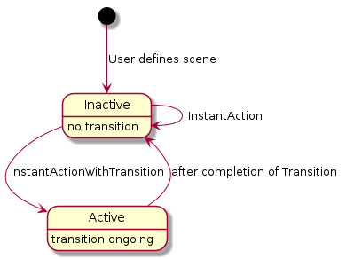
9.14.10.2. Example 2: Set dynamic light effect
User has defined a scene on a number of lights. The corresponding action would have these data fields describing it:
-
Name="sunset"
-
Type=scene
-
EndpointListID references a struct referencing the set of involved endpoints (same as in Example 1)
-
SupportedCommands: StartAction, StartActionWithDuration, StopAction
The StartActionWithDuration command (e.g. triggered by a voice command "play sunset in living room for 1 hour") will trigger the server to activate a dynamic pattern with colors inspired by sunset on the associated lights. At any time, the StopAction can be used to stop the effect.
Please note that the most of the data fields in the ActionStruct for this example are identical to those in example 1 - except for the SupportedCommands. The different sets of supported commands indicate whether it is an instant scene recall (example 1) vs. a long-term dynamic effort (example 2). A server could expose this action also as a single action with the combined set of supported commands.
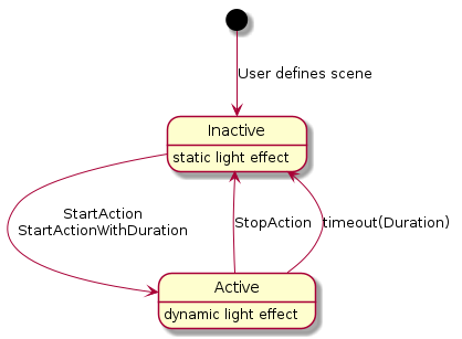
9.14.10.3. Example 3: Pause sensor automation
User has defined an automation: a motion sensor controls the lights in a certain room. Sometimes, they want to override that automatic behavior, e.g. when having a party.
The action for this example would refer to such automation, which is typically active, but can be paused (=temporarily disabled).
The corresponding action would have these data fields describing it:
-
Name="motion sensor"
-
Type=automation
-
EndpointListID references a struct referencing the set of involved endpoints (same as in Example 1)
-
SupportedCommands: EnableAction, DisableAction, PauseAction, PauseActionWithDuration, ResumeAction
Typically, the action has been started when the user defines the motion sensor behavior, so without a Matter command the action’s state would be 'Active'. The PauseActionWithDuration command (e.g. triggered by a voice command "disable the motion sensor in living room for 2 hours") will trigger the server to disable the behavior associated with the motion sensor for the specified time. A ResumeAction command would make this behavior active again. The automation could also have internal logic to abort the disabling after several hours or during the night-time reset, to accommodate for the case the user 'paused' and forgot to 'resume'.
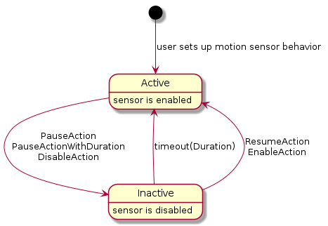
9.14.10.4. Example 4: Wake-up routine
User has defined a wake-up routine: the lights in the bedroom will gradually become brighter and change in color temperature to simulate a sunrise. The sequence lasts for e.g. 30 minutes. Near the end of the sequence, the window coverings would be (partially) opened as well.
The corresponding action would have these data fields describing it:
-
Name="wakeup"
-
Type=sequence
-
EndpointListID references a struct referencing the set of involved endpoints (lights and window coverings in the bedroom)
-
SupportedCommands: EnableAction, DisableAction, DisableActionWithDuration, PauseAction, PauseActionWithDuration
When the user wants to snooze some more, he can use a voice command to trigger the PauseAction command (which could automatically timeout after e.g. 10 minutes). The StopAction command could similarly be used to cancel the remainder of the whole sequence. The DisableActionWithDuration (with parameter 172,800 =2*24*60*60 s) can be used on Friday evening to disable the sequence for the weekend.
When such action has been defined, a Matter node which is aware of the user’s calendar for the day, can use the StartAction command to trigger this sequence of events.
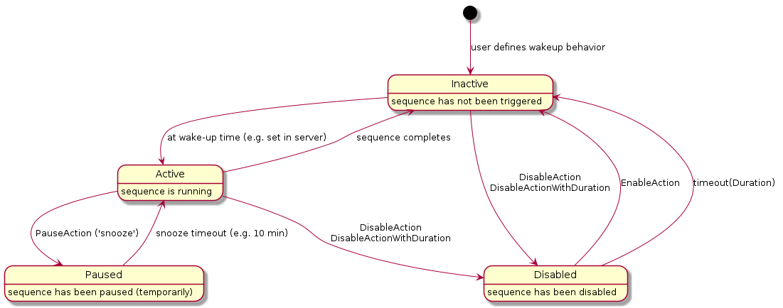
9.14.10.5. Example 5: Scheduled scene recall
User has setup a scene to be recalled at a certain time of day (e.g. colorful garden lighting to switch on around sunset) and switching off those lights (e.g. at midnight). The server’s automation system takes care of this. On certain occasions (e.g. garden party), the user wants to override this behavior (i.e. the scene should not be recalled at sunset because another scene has been set for the party).
The corresponding action would have these data fields describing it:
-
Name="colorful evening garden"
-
Type=automation
-
EndpointListID references a struct referencing the set of involved endpoints (lights in the garden)
-
SupportedCommands: EnableAction, DisableAction, DisableActionWithDuration
After installation, this action is in Inactive state. At the scheduled "on" time, the colorful garden lighting scene is activated and the action’s state changes to the Active state. At the scheduled "off" time, the lights are switched off, and the action’s state changes to the Inactive state. Using the DisableAction, the user can prevent these automated steps to occur - the action’s state changes to the Disabled state. Using the DisableActionWithDuration, the user can do similarly, but also indicate an automatic re-enabling after the specified time period. Using the EnableAction, the user can re-enable the automation.
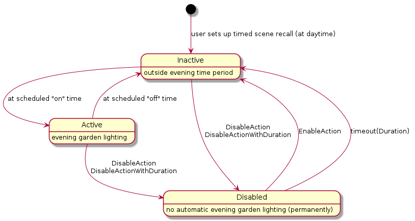
9.14.10.6. Example 6: Alarm system
User has an alarm system which exposes this cluster, with an action that allows to arm/disarm the system by voice commands from a Matter node which is a client to this cluster.
The corresponding action would have these data fields describing it:
-
Name="alarm system"
-
Type=automation
-
EndpointListID references a struct referencing the set of involved endpoints (elements of the alarm system)
-
SupportedCommands: EnableAction, DisableAction, DisableActionWithDuration
After installation, this action could be in Inactive state (assume user is at home installing so system is not armed). Using the EnableAction, the alarm system would be armed. Using the DisableAction, the alarm system would be disarmed (or disarmed for a period with DisableWithDuration).
9.15. Proxy Architecture
|
Note
|
Proxy Architecture, Proxy clusters, and Proxy support, are provisional. |
9.15.1. Motivation
Constrained devices might not support more than a handful of subscriptions. This is usually attributable to a limited memory or battery. However, there might be a large number of clients who desire to subscribe to that device.
9.15.2. Subscription Proxy: Overview
A subscription proxy is a type of Node that is capable of multiplexing subscriptions from multiple subscribers onto a single subscription to a given publisher.
The term 'proxy' is a convenient shorthand that refers to this type of Node.
The term 'source' SHALL refer to a node that serves as the original source of truth for a set of data. The source acts as a publisher of that data.
The term 'client' SHALL refer to a node that wants to subscribe to some source.
A proxy subscribing to a source SHALL surface an identical 'mirror' of the source’s data to downstream clients without the clients having to alter their interaction regardless of whether they are interacting with a proxy or the source itself.
The proxy SHALL be identified by the Subscription Proxy Device Type.

This multiplexing of subscriptions allows the source to delegate all subscriptions to its proxy, only needing to support a single subscription from that proxy. This reduces the demands placed on energy and memory resources. Consequently, that single subscription will encompass the union of all client interest sets. If the combined set of attribute/event paths becomes fairly large, proxies can leverage the use of wildcards to merge multiple localized paths into a single, broader path with wildcards.

A proxy SHALL only proxy subscribe interactions. It SHALL NOT proxy any other type of interaction.
9.15.3. Composition & Paths
A client subscribing to a proxy SHALL specify the Node ID of the source it wishes to subscribe to in the Path. This SHALL be different from the logical destination Node ID of the message, which SHALL be the Node ID of the proxy.

9.15.4. Proxy Subscriptions
9.15.4.1. Overview
A proxy only attempts to subscribe to a source when there is a current, valid subscription from a client to the proxy for that source’s data.
The term 'upstream subscription' refers to the subscription from the proxy either directly to the source, or indirectly to another proxy for that source’s data.
The term 'downstream subscription' refers to the subscription from either a client or another proxy to the proxy in question.
Consequently, when that 'downstream' subscription disappears, the 'upstream' subscription will either be torn down (if there are no other clients interested in that source) or be amended.
This does not require a priori knowledge of a client’s interest set.
9.15.4.2. Upstream/Downstream Subscription Mechanics
Upstream and downstream subscriptions have the following properties:
-
Both subscriptions are independent, but weakly linked.
-
Data is received on the client side, stored on the server side, and used to generate a different set of reports to downstream client(s).
-
-
It is data that is being proxied, not the actual subscription messages themselves.
-
The termination of a downstream subscription will automatically result in an amendment of the upstream subscription to remove the relevant paths that were in the downstream, with a complete termination of the upstream subscription if there was only 1 downstream subscriber present.
-
The disappearance of an upstream subscription will not automatically cancel the downstream subscription.
-
Upstream subscriptions MAY disappear due to network connectivity issues. If an upstream sync report is not received, the proxy SHALL attempt once to re-subscribe to the upstream source; if that re-subscription attempt fails, the proxy SHALL terminate any associated downstream subscriptions.
-
If an upstream subscription is positively terminated by the source as a whole, that will result in a similar termination of the downstream subscription.
-
-
In addition to forwarding status codes embedded in the ReportData from the source, the proxy will convey a special 'NO_UPSTREAM_SUBSCRIPTION' IM status code to the downstream client if it has not established a subscription to the source.
The diagram below gives a sample sequence show-casing the two subscriptions:

9.15.4.3. Sync/Liveness
Since subscriptions provide a 'sync' message to infer health of the subscription on both sides, it allows a client to monitor the health of its source peer.
Conveyance of this is preserved in downstream subscription through the 'NO_UPSTREAM_SUBSCRIPTION' status code. This conveys effectively the same information as the sync message would had the client directly subscribed to the source.
9.15.4.4. Upstream Subscription Parameter Derivation
Since the proxy multiplexes all downstream subscriptions onto a single upstream subscription, it has to have logic to harmonize the various parameters from each client subscription.
The following logic table describes what the proxy SHOULD do:
| Parameter | Suggested Logic |
|---|---|
Attribute/EventPaths |
UNION of all paths. Proxy MAY use wildcards if needed to simplify this logic. |
DataVersionList |
MIN |
EventNumberList |
MIN |
MinimumSyncInterval |
MIN |
MaximumSyncInterval |
MAX |
MinimumReportingIntervalList |
MIN |
ReportableChangeList |
MIN |
Since each client’s interest is different from the final multiplexed subscription, the proxy has to appropriately filter the data being received from the source before sending it to a given client.
9.15.5. Schemas and Data Serialization/Deserialization
Unlike clients that need to semantically interpret data in addition to deserializing/serializing to/from its internal data stores, a proxy only needs to do the latter.
As a result, proxies MAY achieve proxy functionality with a single firmware image built to handle any client, any cluster, any type of device.
9.15.6. Indirect Proxies
A proxy MAY subscribe to another proxy instead of subscribing directly to the source. This creates proxy chains that allow a single source to be proxied by multiple proxies, allowing better use of available proxy capacity.
9.15.7. Proxy Discovery & Assignment Flow
The following flow describes the process by which a client:
-
Discovers that a source needs a proxy
-
Finds an appropriate proxy on the network that is able to handle its request
-
Sets up the proxy to subscribe to the source
9.15.7.1. Step 0: Proxy Setup
A device indicates its ability to act as a certified proxy through stating support for the Subscription Proxy device type.
When such a device is commissioned, the commissioner SHALL recognize this ability and MAY write the NodeIds of all the sources that need proxying into the Proxy Configuration Cluster on the proxy device. Alternatively, it MAY configure the proxy to wildcard proxy all devices, removing the need to specify a particular set of NodeIds.
Additionally, the commissioner MAY write the Node ID of the newly added proxy to the Valid Proxies Cluster on source devices that needs proxying. This cluster stores the static list of candidate proxies for a given device. Only devices that support the cluster would need to have this configuration written.
9.15.7.2. Step 1: Rejection
There unfortunately isn’t any a priori heuristic that MAY be applied to deduce if a source needs proxying. This is usually a function of the number of clients subscribed to a source, the number of paths in those subscriptions, as well as the sync intervals.
When a source cannot handle any more incremental subscriptions, that is when proxying is needed. This is discovered when a client tries to subscribe to the source and is sent back a StatusResponse containing a RESOURCE_EXHAUSTED IM status code, indicating the source’s inability to handle further subscriptions:

In the diagram above, the constraints of the source have been simplified down to having 3 available subscription slots that get filled up.
Upon receipt of the RESOURCE_EXHAUSTED error, the client SHALL invoke the Get Valid Proxies Request command on the source Node. In response, it SHALL receive a Get Valid Proxies Response message containing the NodeIds of valid, candidate proxies.
9.15.7.3. Step 2: Proxy Discovery
After the client has received the list of possible valid proxies, the client MAY attempt to discover a valid proxy that is able to proxy its request.
To do so, the client sends out a Proxy Discover Request Command as a groupcast message to the All Proxies universal group. Before it transmits this message, the client SHALL momentarily subscribe to the IPv6 address that maps to the All Proxies universal group to appropriately receive all responses.

9.15.7.4. Step 3: Proxy Response
Proxies respond to the request with a Proxy Discover Response Command sent as a groupcast message to the All Proxies universal group. A proxy SHALL only send this message when it can handle the subscription request, regardless of whether it is currently subscribed to the source. The response will contain metadata about its ability to handle the subscription.
The Proxy Discover Response Command SHALL be sent as a completely separate, un-related transaction to the original request. The client SHALL correlate the two using the SourceNodeId present in both messages.
Proxies SHALL stagger their responses by waiting for a random interval between 0 and PROXY_SCAN_RESPONSE_JITTER before sending the Proxy Discover Response Command to prevent overwhelming the network or the client, which can be constrained and can have limited buffers.

9.15.7.5. Step 4: Proxy Selection
Client SHALL wait for PROXY_SCAN_PERIOD to aggregate all responses and SHALL filter the set of responses received. Specifically, the client SHALL discard:
-
Responses containing a Source Node ID for other unintended sources
-
Responses containing a Source Node ID in the message that does not match any in the ValidProxyList.
It SHALL then select a proxy from this filtered set based on implementation-chosen policies. One suggested approach would involve selecting the proxy with the least number of hops to the source, followed by largest available capacity.
Clients MAY unsubscribe from the IPv6 multicast group that maps to the All Proxies universal group after aggregating the responses.

9.15.7.6. Step 5: Proxy Subscription
The client then subscribes to the proxy it has selected.
The proxy will do one of two things:
Option 1: If there isn’t another proxy already subscribed to the source, the proxy subscribes to the source directly:

Option 2: If there is already another proxy subscribed to that source, the selected proxy subscribes to that proxy instead.

It doesn’t attempt to subscribe directly to the source since it does not know if the source has any free slots available to support the subscription, risking a potential subscription failure if it did so.
Proxies MAY select between the two options by 'sniffing' the `Proxy Discover Response Command messages that were emitted by other proxies. This allows the candidate proxy to determine whether there is another proxy already subscribed to the source.
A proxy SHALL have only one subscription to a given source regardless of the number of subscription requests from clients for that source. This is necessary to ensure timely ACL enforcement in the case where a client no longer has access to the source, and subsequent state changes will not be made available to that client (see ACL Enforcement for more details).
9.15.7.7. Step 6: Eviction
At this point, the source might not be able to handle another subscription. If so, it SHALL evict non-proxy subscriptions to make space for the proxy subscription. This is acceptable since those clients that got evicted MAY eventually subscribe to a proxy as well.
To make this possible, proxies have to express the type of subscription (proxy or not proxy) in the SubscribeRequest itself.

9.15.7.8. Step 7: Re-Assignment
The evicted clients undergo the same proxy discovery/selection process, and eventually settle on a set of proxies.

9.15.7.9. Notable Characteristics
This algorithm has the following notable characteristics:
-
The system 'auto-balances' based on the needs of clients and the capabilities of the source
-
No persistent state or a priori configuration is needed on any node
-
No a priori heuristics are needed to figure out if a node should be proxied.
-
Robust to proxy failure by leveraging the liveness construct of subscriptions to accelerate discovery
-
No centralized proxy management/assignment service is needed.
-
There is no single point of failure. No need for an election, state backup, or fail-over.
-
-
Low complexity on server (which are usually the more constrained device), slightly more on the client
9.15.8. Constraints
9.15.8.1. Eviction Rules
A source SHALL NOT evict an existing proxy already subscribed to it to make way for a new subscription regardless of whether that new subscription emanates from a proxy or not. This prevents instability in the system since it might result in ping-ponging proxies subscribing to that source.
9.15.8.2. Number of Direct Proxies
There SHOULD only be one proxy node directly subscribed to a source in a single-fabric setting. This is not enforced by the source but rather, by proxies themselves.
9.15.8.3. Multi-Fabric
In a multi-fabric setting, a source node MAY be subscribed to by clients commissioned into different fabrics. It is highly desirable that a single proxy interacting with a source support clients from multiple fabrics. To make this possible, a proxy SHOULD when possible, be commissioned into all fabrics that contain sources that need proxying.
If a proxy is not commissioned into all fabrics, it might not see another proxy’s Proxy Discover Response Command messages, nor will it be capable of directly subscribing to that proxy even if it did, since it doesn’t have credentials to do so. This MAY result in multiple proxies attempting to subscribe directly to the source, resulting in potential rejection by the source and consequently, an inability for a client’s subscription to be served indirectly through that chosen proxy. This might be unpredictable depending on which proxy was able to subscribe first to that source.
9.15.9. Certification
To ensure a consistent expectation of behavior from a proxy device, the proxy SHOULD be certified by the Connectivity Standards Alliance against the expectations of a proxy. Once certified, it MAY claim compatibility against the Subscription Proxy device type.
9.15.10. Security & Privacy
9.15.10.1. Authentication
To prevent malicious or unattested devices from acting as proxies to clients, the Valid Proxies Cluster provides a scheme for admins to specify the NodeIds of valid, attested proxies to the source itself, which is in turn conveyed to clients. This allows for filtering of the ensuing Proxy Discover Response Command messages to only select valid, trusted proxies.
9.15.10.2. Multicast Messages
The proxy discovery commands SHALL be encrypted with a fabric-provided group key. An Administrator that wishes to enable proxy functionality on a set of clients SHALL bind the All Proxies group to a specific group key in the Group Key Management cluster.
Consequently, a Proxy Discover Request Command message SHALL be sent for every All Proxies GroupID instance specified in the Group Keys Management cluster.
9.15.10.3. ACL Enforcement
Administrators SHOULD configure source nodes to grant the 'Proxy View' privilege to proxy clients. If this privilege is not granted for at least the Access Control cluster, the proxy will not function. This privilege SHOULD be granted for the entire source node for a proxy to be most effective, since neither the proxy nor the Administrator can predict which source clusters may be subscribed by other clients.
The proxy SHALL subscribe to the Access Control Cluster on the source and SHALL enforce the source’s ACLs on behalf of the source when serving its downstream client subscriptions.
The proxy MAY enforce the source’s ACLs eagerly (i.e. at first ACL change), lazily (i.e. at next data report), or by some combination of these approaches. The key guarantee is that the proxy SHALL apply the latest source ACLs from its upstream subscription at the time it generates associated downstream subscription reports.
The proxy SHALL enforce the source’s ACLs on a path by path basis, in a similar manner to how the Access Control Privilege Granting algorithm enforces access. Downstream subscription paths that are not granted access by the proxy SHALL cause the proxy to generate an UNSUPPORTED_ACCESS error for that subscription path.
If all report data paths in a downstream subscription result in UNSUPPORTED_ACCESS error, the proxy SHALL tear down that downstream subscription.
If the proxy is not able to view the source’s Access Control Cluster due to insufficient privileges, it SHALL NOT generate any downstream subscription data reports for that source. Instead, the proxy SHALL generate a report containing UNSUPPORTED_ACCESS errors for each path in the downstream subscription and tear down the downstream subscription.
9.15.11. Parameters and Constants
Table 83, “Glossary of constants” is a glossary of constants used in this section, along with a brief description and example default for each constant.
| Constant Name | Description | Default Value |
|---|---|---|
PROXY_SCAN_RESPONSE_JITTER |
The maximum amount of time to randomly wait before sending a |
1000 milliseconds |
PROXY_SCAN_PERIOD |
The maximum amount of time initiator of proxy discovery will wait to collect |
1100 milliseconds |
9.15.13. Proxy Discovery Cluster
This cluster contains commands needed to do proxy discovery as defined in the Section 9.15.7.3, “Step 2: Proxy Discovery” and Section 9.15.7.4, “Step 3: Proxy Response” steps of the overall Section 9.15.7, “Proxy Discovery & Assignment Flow”.
9.15.13.1. Revision History
-
The global ClusterRevision attribute value SHALL be the highest revision number in the table below.
| Revision | Description |
|---|---|
1 |
Initial Release |
9.15.13.2. Classification
| Hierarchy | Role | Context | PICS Code |
|---|---|---|---|
Base |
Utility |
Node |
PXDSC |
9.15.13.3. Cluster Identifiers
| Identifier | Name |
|---|---|
0x0043 |
ProxyDiscovery |
9.15.13.5. Commands
| Id | Name | Direction | Response | Access | Conformance |
|---|---|---|---|---|---|
0x00 |
Proxy Discover Request |
Client ⇒ Server |
N |
O |
M |
0x01 |
Proxy Discover Response |
Server ⇒ Client |
N |
M |
9.15.13.5.1. Proxy Discover Request Command
This command is used during proxy discovery, as specified in Section 9.15.7, “Proxy Discovery & Assignment Flow”.
| Id | Field | Type | Constraint | Quality | Default | Conformance |
|---|---|---|---|---|---|---|
0 |
SourceNodeId |
node-id |
all |
M |
||
1 |
NumAttributePaths |
uint16 |
desc |
M |
||
2 |
NumEventPaths |
uint16 |
desc |
M |
9.15.13.5.2. SourceNodeId
This is the Node ID of the source for which a client seeks to find a Proxy.
9.15.13.5.3. NumAttributePaths
The number of attribute paths the client will have in the subscription request. This is a heuristic/hint to allow a Proxy to better ascertain whether it can support the ensuing subscription.
9.15.13.5.4. NumEventPaths
The number of event paths the client will have in the subscription request. This is a heuristic/hint to allow a Proxy to better ascertain whether it can support the ensuing subscription.
9.15.13.5.5. Proxy Discover Response Command
This command is used during proxy discovery, as specified in Section 9.15.7, “Proxy Discovery & Assignment Flow”.
| Id | Field | Type | Constraint | Quality | Default | Conformance |
|---|---|---|---|---|---|---|
0 |
SourceNodeId |
node-id |
all |
M |
||
1 |
NumHopsToSource |
uint16 |
desc |
M |
||
2 |
AvailableCapacity |
uint16 |
desc |
M |
This is the Node ID of the source the proxy can proxy for. This SHALL match the node id in the corresponding Proxy Discover Request Command message.
If the proxy currently subscribes to the source (either directly or indirectly), this indicates the number of hops to the source. Sensible values start at 1, with 1 being used for a proxy that subscribes directly to the source. If the proxy is not subscribed directly to the source, this value SHALL be one greater than the NumHopsToSource for the given Node ID of the proxy it is subscribed to.
0 indicates that the proxy currently does not have a subscription to the source.
A number indicating the number of Cluster Attribute Paths the proxy has space for support. This allows for an absolute comparison of different memory capacities of candidate proxies by the client in selecting the best possible candidate.
9.15.14. Proxy Configuration Cluster
This cluster provides a means for a proxy-capable device to be told the set of Nodes it SHALL proxy.
9.15.14.1. Revision History
-
The global ClusterRevision attribute value SHALL be the highest revision number in the table below.
| Revision | Description |
|---|---|
1 |
Initial Release |
9.15.14.2. Classification
| Hierarchy | Role | Context | PICS Code |
|---|---|---|---|
Base |
Utility |
Node |
PXCFG |
9.15.14.3. Cluster Identifiers
| Identifier | Name |
|---|---|
0x0042 |
ProxyConfiguration |
9.15.14.4. Definitions
9.15.14.4.1. ConfigurationStruct
| Quality: Fabric-Scoped | |||||||
|---|---|---|---|---|---|---|---|
Id |
Name |
Type |
Constraint |
Quality |
Access |
Default |
Conformance |
1 |
ProxyAllNodes |
bool |
desc |
RW |
false |
M |
|
2 |
SourceList |
list[node-id] |
desc |
RW |
empty |
M |
|
This field SHALL be set to to 'true' to indicate to the proxy that it SHALL proxy all nodes. When 'true', the
SourceList attribute is ignored.
When ProxyAllNodes is 'false', this list contains the set of NodeIds of sources that this proxy SHALL specifically proxy.
9.15.14.5. Server Attributes
| Id | Name | Type | Range | Quality | Access | Default | Conformance |
|---|---|---|---|---|---|---|---|
0 |
ConfigurationList |
list[ConfigurationStruct] |
all |
N |
RW |
empty |
M |
9.15.14.5.1. ConfigurationList
List of proxy configurations. There SHALL NOT be multiple entries in this list for the same fabric.
9.15.15. Valid Proxies Cluster
This cluster provides a means for a device to be told of the valid set of possible proxies that can proxy subscriptions on its behalf as per Section 9.15.7, “Proxy Discovery & Assignment Flow”.
9.15.15.1. Revision History
-
The global ClusterRevision attribute value SHALL be the highest revision number in the table below.
| Revision | Description |
|---|---|
1 |
Initial Release |
9.15.15.2. Classification
| Hierarchy | Role | Context | PICS Code |
|---|---|---|---|
Base |
Utility |
Node |
PXVALID |
9.15.15.3. Cluster Identifiers
| Identifier | Name |
|---|---|
0x0044 |
ValidProxies |
9.15.15.4. Definitions
9.15.15.4.1. ValidProxyStruct
Encapsulates the Node ID of a Valid Proxy.
| Quality: Fabric-Scoped | |||||||
|---|---|---|---|---|---|---|---|
Id |
Name |
Type |
Constraint |
Quality |
Access |
Default |
Conformance |
1 |
NodeID |
node-idx |
all |
RW |
M |
||
9.15.15.5. Server Attributes
| Id | Name | Type | Range | Quality | Access | Default | Conformance |
|---|---|---|---|---|---|---|---|
0 |
ValidProxyList |
list[ValidProxyStruct] |
N/A |
N F |
RW |
empty |
M |
9.15.15.5.1. ValidProxyList
List of valid proxies that can proxy this Node. Each entry in this list is fabric-scoped.
9.15.15.6. Commands
| Id | Name | Direction | Response | Access | Conformance |
|---|---|---|---|---|---|
0x00 |
Get Valid Proxies Request |
Client ⇒ Server |
Get Valid Proxies Response |
O |
M |
0x01 |
Get Valid Proxies Response |
Server ⇒ Client |
N |
M |
9.15.15.6.1. Get Valid Proxies Request
This command is used during proxy discovery, as specified in Section 9.15.7, “Proxy Discovery & Assignment Flow”.
This command has an empty payload.
9.15.15.6.2. Get Valid Proxies Response
This command is used during proxy discovery, as specified in Section 9.15.7, “Proxy Discovery & Assignment Flow”.
| Id | Field | Type | Constraint | Quality | Default | Conformance |
|---|---|---|---|---|---|---|
0 |
ProxyNodeIdList |
list[node-id] |
M |
9.15.15.6.3. ProxyNodeList
This contains the list of node ids stored in the ValidProxyList whose associated fabric matches the accessing fabric.
10. Interaction Model Encoding Specification
10.1. Overview
This specification details the encoding of the Interaction Model (IM) in the Matter TLV format.
Specifically, it details the encoding of the application payload for Matter messages that map to the Interaction Model. The details of the message header are described in Section 4.4, “Message Frame Format” and out of scope of this document.
10.2. Messages
10.2.1. IM Protocol Messages
Each Action in the IM specification SHALL be mapped to a message with a unique Protocol Opcode, namespaced under the PROTOCOL_ID_INTERACTION_MODEL Protocol ID.
-
Vendor ID = 0x0000 (Matter Common)
| Protocol Opcode | Action | Message |
|---|---|---|
0x01 |
Status Response |
|
0x02 |
Read Request |
|
0x03 |
Subscribe Request |
|
0x04 |
Subscribe Response |
|
0x05 |
Report Data |
|
0x06 |
Write Request |
|
0x07 |
Write Response |
|
0x08 |
Invoke Request |
|
0x09 |
Invoke Response |
|
0x0A |
Timed Request |
10.2.2. Common Action Information Encoding
Every action SHALL encode the fields specified in Section 8.2.5.1, “Common Action Information”. The methods for encoding Common Action Information fields are:
-
As a field in the message header
-
As a context tagged field in the action payload
For every field appearing in TLV-encoded data described by the schemas of the following sections, and where a context-specific tag is used, any context-specific tag not listed in a given schema SHALL be reserved for future use and SHALL be silently ignored by clients and servers if seen in a payload.
10.2.2.1. Message Header Encoded Action Information
The following Common Action Information fields are encoded into the message header:
| Header Field | Type | Description |
|---|---|---|
Message Exchange ID |
16-bit integer |
Used to convey the Transaction ID |
Source Node ID |
64-bit integer |
Node ID of the source that generated the transaction |
Destination ID |
64-bit integer |
Either a Node ID or Group ID is encoded in here depending on what the IM indicates |
Protocol ID |
32 bits |
The protocol to which this message belongs; all messages in this spec SHALL use the |
Protocol OpCode |
8 bits |
The specific message type |
10.2.2.2. Context Tag Encoded Action Information
The following Common Action Information fields are encoded as context tagged fields in the action message payload. All action messages defined in Section 10.6, “Message Definitions” SHALL include these tagged fields:
| Common Action Field | Context Tag |
|---|---|
InteractionModelRevision |
0xFF |
10.2.3. Chunking
Chunking is the act of splitting an Action that contains attribute/event data, specifically ReportData and WriteRequest actions, into multiple messages at logical boundaries due to the size limitations imposed by IPv6 for UDP packets (see Section 4.4.4, “Message Size Requirements” for more details).
Since attribute/event data within Actions are already organized into a series of AttributeDataIBs (for attributes) and EventDataIBs for event records, chunking entails maximally packing these information blocks (IBs) into a series of 'data' messages.
To ensure in-order delivery of a chunked set of IBs, each data message requires a response before the next data message can be sent. For ReportDataMessage and WriteRequestMessage, a StatusResponseMessage and WriteResponseMessage are the respective response messages.
A MoreChunkedMessages flag SHALL be set on every data message except the last to convey to the receiver possible delivery of more chunked messages within a given Action. This is specified in the WriteRequestMessage and ReportDataMessage.
While most data types can be easily encoded in this scheme to fit within a message, the fact that lists can be of variable, and arbitrary, length can lead to complications. Specific strategies to encode lists that are chunking friendly are provided in Section 10.5.4.3.1, “Lists”.
10.2.4. Transaction Flows
10.2.4.1. Read (Success)

10.2.4.2. Read (Server Error)

10.2.4.3. Read (Client Error)

10.2.4.4. Write (Success)

10.2.4.5. Write (Server Error)

10.2.4.6. Subscribe (Success)

10.2.4.7. Subscribe (Server Error)

10.2.4.8. Subscribe (Client Error)

10.3. Data Types
The IM specification defines a number of schema data types that are usable in a given cluster schema definition.
This section will outline their encoding onto TLV wire types, and their specific representations.
| Class | Schema Data Type | TLV Type |
|---|---|---|
Analog |
uint8, uint16, uint24, uint32, uint40, uint48, uint56, uint64 |
Unsigned Integer (width is selected automatically depending on data value) |
int8, int16, int24, int32, int40, int48, int56, int64 |
Signed Integer (width is selected automatically depending on data value) |
|
float32 |
Floating Point Number, 4-byte value |
|
float64 |
Floating Point Number, 8-byte value |
|
Discrete |
enum8, enum16, enum32 |
Unsigned Integer (width is selected automatically depending on data value) |
data8, data16, data32, data64 |
Unsigned Integer (width is selected automatically depending on data value) |
|
map8, map16, map32, map64 |
Unsigned Integer (width is selected automatically depending on data value) |
|
boolean |
Boolean |
|
Composite |
UTF-8 string (length is selected automatically depending on data value) |
|
TLV octet string |
||
Collection |
list |
TLV array |
struct |
TLV structure |
10.3.1. Analog - Integer
All signed integer schema types SHALL be encoded using the TLV signed integer type. The specific TLV element type (1-byte, 2-byte, 4-byte and 8-byte signed integer types) SHALL be selected automatically at runtime depending on the actual value.
In this regard, the actual width of the over-the-wire type can be narrower than the width specified in schema.
E.g. a 32-bit value defined in schema will be encoded to a 1-byte TLV signed integer type if the value doesn’t exceed (-128 to +127).
Similarly, all unsigned integer schema types SHALL be encoded using the TLV unsigned integer type.
10.3.2. Analog - Floating Point
Both single and double precision floating point analog schema types SHALL be encoded using equivalent TLV floating point types as well.
10.3.3. Discrete - Enumeration
Enumerations SHALL be encoded using the TLV unsigned integer type, with the width selected automatically at runtime based on the actual value.
10.3.4. Discrete - Bitmap
Bitmaps SHALL be encoded using the TLV unsigned integer type, with the width selected automatically at runtime based on the actual value.
10.3.5. Composite - String
While strings are a derived data type, they SHALL be encoded using the TLV UTF-8 string type.
10.3.6. Composite - Octet String
Octet strings SHALL be encoded using TLV Byte Strings.
10.3.7. Collection - Struct
Structure types in schema SHALL be encoded using the TLV structure type.
10.3.8. Collection - List
The entirety of a list SHALL be encoded as a TLV array.
A list index SHALL start at 0.
Lists shall have a maximum size of 65535 elements (216-1).
10.3.9. Derived Types
All derived types (with the exception of strings) SHALL be encoded according to their base type.
10.3.10. Field IDs
Field IDs SHALL be encoded as:
-
A context tag when the MEI prefix encodes a standard/scoped source.
-
A fully-qualified profile-specific tag when the MEI prefix encodes a manufacturer code. The Vendor ID SHALL be set to the manufacturer code, the profile number set to 0 and the tag number set to the MEI suffix.
|
Note
|
Support for encoding Field IDs with an MC source is provisional. |
10.4. Sample Cluster
This section defines a sample cluster (with attributes, events, and commands) for illustrative purposes; it SHALL NOT be interpreted as a real cluster.
10.4.1. Disco Ball Cluster
This example cluster controls an imaginary mirrored disco ball, for the express purpose of disco dancing.
10.4.1.1. Revision History
The global ClusterRevision attribute value SHALL be the highest revision number in the table below.
| Revision | Description |
|---|---|
1 |
Initial Release |
2 |
Deprecated Off enum value in Rotate attribute |
3 |
Added pattern list feature |
4 |
Added Name attribute |
5 |
Added Reverse feature |
6 |
Updated columns from Data & Interaction Model specs |
10.4.1.2. Classification
| Hierarchy | Role | Scope | PICS Code |
|---|---|---|---|
Base |
Application |
Endpoint |
DISCO |
10.4.1.3. Cluster Identifiers
| Identifier | Name |
|---|---|
0x3456 |
Disco Ball |
10.4.1.4. Features
This cluster SHALL support the FeatureMap bitmap attribute as defined below.
| Bit | Code | Feature | Description |
|---|---|---|---|
0 |
AX |
Axis |
Allows the disco ball rotational axis to change |
1 |
WBL |
Wobble |
Allows the disco ball to wobble on its axis as speed (dependent on Axis) |
2 |
PAT |
Pattern |
Supports a list of patterns to cycle through automatically |
3 |
STA |
Statistics |
Supports a request to statistics |
4 |
REV |
Reverse |
Supports a Reverse command and counterclockwise rotation |
10.4.1.5. Attributes
| ID | Name | Type | Constraint | Quality | Default | Access | Conformance |
|---|---|---|---|---|---|---|---|
0x0000 |
Run |
bool |
all* |
0 |
R V T* |
M |
|
0x0001 |
Rotate |
desc* |
0 |
R V |
M |
||
0x0002 |
Speed |
uint8 |
0 to 200* |
0 |
R V |
M |
|
0x0003 |
Axis |
uint8 |
0 to 90 |
0 |
RW VO |
AX | WBL |
|
0x0004 |
WobbleSpeed |
uint8 |
0 to 200 |
0 |
RW VO |
WBL |
|
0x0005 |
Pattern |
list[PatternStruct] |
max 16* |
0 |
RW M |
PAT |
|
0x0006 |
Name |
string |
max 16 |
N* |
0 |
RW VM |
O |
10.4.1.5.1. Run Attribute
This SHALL indicate if the disco ball is operating. If the Run attribute is 0, then the Speed, Rotate and WobbleSpeed attributes SHALL be 0.
10.4.1.5.2. Rotate Attribute
This SHALL indicate the direction of rotation either clockwise or counterclockwise.
10.4.1.5.3. Speed Attribute
This SHALL indicate the speed of the disco ball in revolutions per minute.
10.4.1.5.4. Axis Attribute
This SHALL indicate the tilt of the axis of the disco ball, in degrees.
10.4.1.5.5. WobbleSpeed Attribute
This SHALL indicate the speed of the wobble rotation in revolutions per minute.
10.4.1.5.6. Pattern Attribute
This is an ordered list of entries. Entries may be appended or prepended, but not inserted. This list of patterns SHALL be used to operate the disco ball when the Pattern Request command is invoked.
10.4.1.5.7. Name Attribute
This SHALL indicate a display name.
10.4.1.6. Commands
| ID | Name | Direction | Response** | Access | Conformance |
|---|---|---|---|---|---|
0x00 |
Start Request |
client ⇒ server |
Y |
O T* |
M |
0x01 |
Stop Request |
client ⇒ server |
Y |
O |
M |
0x02 |
Reverse Request |
client ⇒ server |
Y |
O |
REV |
0x03 |
Wobble Request |
client ⇒ server |
Y |
O |
WBL |
0x04 |
Pattern Request |
client ⇒ server |
Y |
M |
PAT |
0x05 |
Stats Request |
client ⇒ server |
Stats Response** |
O |
STA |
0x06 |
Stats Response |
client ⇐ server |
N |
O |
STA |
10.4.1.6.1. Start Request Command
Upon receipt, this SHALL start the disco ball rotating using the data as follows:
| Id | Name | Type | Constraint | Quality | Default | Conformance |
|---|---|---|---|---|---|---|
0 |
Speed |
uint8 |
max 200 |
MS* |
M |
|
1 |
Rotate |
desc |
Clockwise |
O |
This SHALL indicate the rotation speed.
This SHALL indicate the rotation direction.
10.4.1.6.2. Pattern Request Command
If the passcode field is an empty string, this SHALL start the disco ball rotating using unprotected (i.e patterns that have no passcode) pattern list entries in sequence to control the disco ball. When the final entry in the list is processed the sequence SHALL restart at the first entry.
If the passcode field is not an empty string, only the patterns that correspond to the provided passcode SHALL be invoked.
| ID | Name | Type | Constraint | Quality | Access | Default | Conformance |
|---|---|---|---|---|---|---|---|
0 |
Passcode |
string |
max 6 |
empty |
M |
10.4.1.6.3. Stop Request Command
Upon receipt, this SHALL stop the disco ball rotating, and SHALL set the Run, Speed and Rotate attributes to 0.
10.4.1.6.4. Reverse Request Command
Upon receipt, this SHALL reverse the direction of the disco ball rotation. This command MAY generate an error response of UNSUPPORTED_PATTERN.
10.4.1.6.5. Wobble Request Command
Upon receipt, this SHALL wobble the disco ball on its axis at the speed in the WobbleSpeed attribute. This command MAY generate an error response of UNSUPPORTED_PATTERN.
10.4.1.6.6. Stats Request Command
Upon receipt, this SHALL generate a Stats Response command.
10.4.1.6.7. Stats Response Command
This command SHALL be generated in response to a Stats Request command. The data for this command SHALL be as follows:
| ID | Name | Type | Constraint | Quality | Default | Conformance |
|---|---|---|---|---|---|---|
0 |
LastRun |
uint32 |
all |
0 |
M |
|
1 |
Patterns |
uint32 |
all |
0 |
[PAT] * |
This SHALL indicate the duration in seconds for the last time the disco ball was run.
This SHALL indicate the number of pattern changes from the Pattern attribute attribute within the last run time.
10.4.1.7. Events
| ID | Name | Priority | Access | Conformance |
|---|---|---|---|---|
0 |
Started |
INFO |
V* |
M |
1 |
Stopped |
INFO |
V |
M |
2 |
PatternChange |
INFO |
V |
[PAT] |
10.4.1.7.1. Started Event
This event SHALL be generated, when the Run attribute changes from false to true.
There is no data for this event.
10.4.1.7.2. Stopped Event
This event SHALL be generated, when the Run attribute changes from true to false.
There is no data for this event.
10.4.1.7.3. Pattern Change Event
This event SHALL be generated when the Rotate, Speed, or WobbleSpeed attributes are written or changed locally as the result of processing the Pattern attribute list.
| ID | Name | Type | Constraint | Quality | Default | Conformance |
|---|---|---|---|---|---|---|
0 |
PrevPattern |
X |
null |
M |
||
1 |
CurPattern |
M |
||||
2 |
NextPattern |
X |
null |
M |
The CurPattern field SHALL be the current pattern being run. The PrevPattern event field SHALL be the previous pattern run. If there is no previous pattern, then PrevPattern SHALL be null. The NextPattern event field SHALL be the next in the pattern list. If there is no next pattern, the NextPattern event field SHALL be null.
10.4.1.8. Data Types
10.4.1.8.1. RotateEnum
The data type of the Rotate attribute is derived from enum8.
| Value | Name | Description | Conformance |
|---|---|---|---|
0 |
Off |
Rotation is currently off |
D* |
1 |
Clockwise |
Rotation is currently clockwise |
M |
2 |
CounterClockwise |
Rotation is currently counterclockwise |
REV |
10.4.1.8.2. PatternStruct
This indicates a pattern of operation for a running disco ball.
| Access Quality: Fabric Scoped | |||||||
|---|---|---|---|---|---|---|---|
ID |
Name |
Type |
Constraint |
Quality |
Access |
Default |
Conformance |
0 |
Duration |
uint16 |
all |
RW |
0 |
M |
|
1 |
Rotate |
desc |
X* |
RW |
null* |
M |
|
2 |
Speed |
uint8 |
max 200 |
X |
RW |
null |
M |
3 |
Axis |
uint8 |
max 90 |
X |
RW |
null |
AX | WBL |
4 |
WobbleSpeed |
uint8 |
max 200 |
X |
RW |
null |
WBL |
5 |
Passcode |
string |
all |
X |
RWS |
null |
M |
This SHALL indicate the time in seconds for the disco ball to perform the pattern.
This SHALL indicate the rotation direction or null to not change the direction.
This SHALL indicate the speed of the rotation, or null to not change the speed.
This SHALL indicate the angle of the axis of rotation, or null to not change the angle.
This SHALL indicate the speed of the axis wobble, or null to not change the speed.
An optionally specified passcode that if present, needs to always be provided in the Pattern Request command to successfully invoke this pattern.
10.4.1.9. Status Codes
Listed below are cluster specific status codes only indicated for a particular instance of this cluster.
| Code | Status | Description |
|---|---|---|
2* |
UNSUPPORTED_PATTERN |
The movement pattern is unsupported on the device even though all values are within constraints |
10.4.2. Super Disco Ball Cluster
This is derived* from the Disco Ball cluster, with overrides for qualities and conformance.
10.4.2.1. Revision History
The global ClusterRevision attribute value SHALL be the highest revision number in the table below.
| Revision | Description |
|---|---|
1 |
Initial Release |
10.4.2.2. Classification
| Hierarchy | Role | Context | PICS Code |
|---|---|---|---|
Disco Ball |
Application |
Endpoint |
SUPDISC |
10.4.2.3. Cluster Identifiers
| Identifier | Name |
|---|---|
0xBBCC |
Super Disco Ball |
10.4.2.4. Features
| Bit | Feature | Conformance |
|---|---|---|
0 |
Axis |
M |
1 |
Wobble |
M |
2 |
Pattern |
M |
3 |
Statistics |
M |
4 |
Reverse |
M |
10.4.2.5. Attributes
| ID | Name | Type | Constraint | Quality | Default | Access | Conformance |
|---|---|---|---|---|---|---|---|
0x0006 |
Name |
string |
max 32 |
M |
10.4.2.6. Events
| ID | Name | Priority | Access | Conformance |
|---|---|---|---|---|
2 |
PatternChange |
M |
10.5. Information Blocks
These are elements that may apply to multiple message types, and are defined in a common way to permit re-use as a definition. Unless stated otherwise, these correspond to their identically named counterparts in the Interaction Model Specification.
10.5.1. Tag Rules
Unless otherwise noted, all context tags SHALL be emitted in the order as defined in the appropriate specification. This is done to reduce receiver side complexity in having to deal with arbitrary order tags.
10.5.2. AttributePathIB
TLV Type: List |
|||||
Tag |
Comments |
Tag Type |
Tag Number |
TLV Type |
Range |
|---|---|---|---|---|---|
|
Context Tag |
0 |
bool |
- |
|
|
Context Tag |
1 |
Unsigned Int |
64 bits |
|
|
Context Tag |
2 |
Unsigned Int |
16 bits |
|
|
Context Tag |
3 |
Unsigned Int |
32 bits |
|
|
Context Tag |
4 |
Unsigned Int |
32 bits |
|
|
Context Tag |
5 |
Unsigned Int |
16 bits, nullable |
|
-
The contents of ClusterPathIB in the Interaction Model specification have been expanded here for encoding efficiency.
-
The ClusterPathIB Group field is omitted here (see Node field description).
-
Maximum nesting is restricted to referencing a list element in an attribute. Consequently, the
NestedPathfield is removed and replaced with a singleListIndexfield.
10.5.2.1. EnableTagCompression
This tag is used to select between two different interpretations on the receiver when the Node, Endpoint, Cluster, Attribute tags are omitted:
-
When false or not present, omission of any of the tags in question (with the exception of
Node) indicates wildcard semantics. -
When true, indicates the use of a tag compression scheme. In this case the value for any omitted tag SHALL be set to the value for that tag in the last AttributePathIB that had
EnableTagCompressionnot present or set to false and was seen in a message that is part of the same interaction model Action as the current message.-
The AttributePathIB the values end up coming from MAY appear in the same message (but earlier in it) as the current AttributePathIB.
-
The values that come from the previous AttributePathIB MAY still be missing. In that case, with the exception of
Node, they indicate wildcard semantics.
-
10.5.2.2. Node
-
If the
Groupfield is present in the IM representation, the Group ID is encoded in the DST field in the message header and elided from the encoding here. -
The
Nodetag MAY be omitted if the target node of the path matches the NodeID of the server involved in the interaction.
10.5.2.3. Endpoint, Cluster
-
Each of these tags can be omitted. The semantics of such omission depend on the value of
EnableTagCompression.
10.5.2.4. Attribute, ListIndex
-
When
EnableTagCompressionis false or not present, they have the following semantics:
| Attribute | ListIndex | Description |
|---|---|---|
Omitted |
Omitted |
Selects all attributes within the specified Node, Endpoint, Cluster |
Present |
Omitted |
Selects a specific attribute within the specified Node, Endpoint, Cluster. |
Present |
Present |
Selects a specific list item within a top-level attribute of type list. |
This does not allow expressing all possible paths defined in the interaction model. Only paths that can be expressed MAY be used.
-
The
ListIndextag is nullable. The null value SHALL only be used when this AttributePathIB is used in an AttributeDataIB and indicates a list append operation. See Section 10.5.4.3.1, “Lists” for more details.
10.5.2.5. Examples
Select all attributes on a given cluster and endpoint:
AttributePath = [[ Endpoint = 10, Cluster = Disco Ball ]]
Select all attributes in all clusters on a given endpoint:
Path = [[ Endpoint = 10 ]]
Select all attributes in all clusters on the node:
Path = [[ ]]
Select a specific attribute:
Path = [[ Endpoint = 10, Cluster = Disco Ball, Attribute = Axis ]]
Select a specific item in a top-level list:
Path = [[ Endpoint = 10, Cluster = Disco Ball, Attribute = Pattern, ListIndex = 4 ]]
Select all attributes in all clusters on a given endpoint on a proxied node:
Path = [[ Node = 0x18B430003020203, Endpoint = 10 ]]
Tag Compression Example #1:
Path1 = [[ Node = 0x18B430003020203, Endpoint = 10, Cluster = Disco Ball, Attribute = Pattern, ListIndex = 3 ]] // Start tracking path elements. Path2 = [[ EnableTagCompression = true, ListIndex = 4 ]] // Node, Endpoint, Cluster, Attribute are re-used from Path1 Path3 = [[ EnableTagCompression = true, ListIndex = 5 ]] // Node, Endpoint, Cluster, Attribute are re-used from Path1 Path4 = [[ EnableTagCompression = true, Attribute = Axis ]] // Endpoint, Cluster are re-used from Path1
Tag Compression Example #2:
Path1 = [[ Node = 0x18B430003020203, Cluster = Disco Ball, Attribute = Pattern, ListIndex = 3 ]] // Endpoint is wildcard, start tracking path elements. Path2 = [[ EnableTagCompression = true, ListIndex = 4 ]] // Node, Endpoint (including wildcard), Cluster, Attribute are re-used from Path1 Path3 = [[ EnableTagCompression = true, ListIndex = 5 ]] // Node, Endpoint (including wildcard), Cluster, Attribute are re-used from Path1
Tag Compression Example #3:
Path1 = [[ Node = 0x18B430003020203, Endpoint = 10, Cluster = Disco Ball, Attribute = Pattern, ListIndex = 3 ]] // Start tracking path elements. Path2 = [[ EnableTagCompression = true, ListIndex = 4 ]] // Node, Endpoint, Cluster, Attribute are re-used from Path1 Path3 = [[ EnableTagCompression = true, ListIndex = 5 ]] // Node, Endpoint, Cluster, Attribute are re-used from Path1 Path4 = [[ Node = 0x18B430003020203, Endpoint = 20, Cluster = Disco Ball, Attribute = Axis ]] // Reset tracker variables Path5 = [[ EnableTagCompression = true, Attribute = Pattern, ListIndex = 5]] // Node, Endpoint, Cluster are re-used from Path4.
10.5.3. DataVersionFilterIB
| TLV Type: Structure | |||||
|---|---|---|---|---|---|
Element |
Comments |
Tag Type |
Tag Number |
Type |
Range |
|
Context Tag |
0 |
- |
||
|
Context Tag |
1 |
Unsigned Int |
32 bits |
|
10.5.4. AttributeDataIB
| TLV Type: Structure | |||||
|---|---|---|---|---|---|
Element |
Comments |
Tag Type |
Tag Number |
Type |
Range |
|
Context Tag |
0 |
Unsigned Int |
32 bits |
|
|
Context Tag |
1 |
- |
||
|
Context Tag |
2 |
Variable (see below) |
- |
|
-
The
Changefield in the Interaction Model specification is not encoded directly. Instead, it is encoded through the use of special values in thePathandDatafields (see Lists below.
10.5.4.1. DataVersion
This tag can be omitted if the value of EnableTagCompression in the Path field is true. In this case, the value for the omitted tag SHALL be set to the value for that tag (if present) in the last AttributeDataIB that had tag compression disabled (i.e EnableTagCompression not present or set to false) and was seen in a message that is part of the same interaction model Action as the current message. If this tag was not present and tag compression was disabled, it SHALL be interpreted as though a data version was not specified in that, or subsequent AttributeDataIBs.
10.5.4.2. Path
In addition to the rules specified for AttributePathIB, the Attribute and 'Cluster' fields within that element SHALL always be present.
10.5.4.3. Data
Upon path expansion of the value in Path, the hierarchy and structure of the encoded data for each concrete Path SHALL be based on the schema description of the specified attribute within the specified cluster. The TLV encoding of each element in the data SHALL follow the rules of encoding as provided in Data Types.
10.5.4.3.1. Lists
The various values in the Change enumeration are realized as follows:
| Change Type | Realization |
|---|---|
REPLACE |
|
ADD |
|
DELETE |
|
MODIFY |
|
-
A single AttributeDataIB containing a path to the list itself and Data that contains all items in the list encoded as a TLV array. This option SHOULD be selected if it is possible to encode the entirety of the list in a single AttributeDataIB that fits in a single message.
-
A series of AttributeDataIBs, with the first containing a path to the list itself and Data that is an empty array, which signals clearing the list, and subsequent AttributeDataIBs each containing a path to each list item, in order, and Data that contains the value of the list item. This option SHOULD be selected when it is not possible to encode the entirety of the list in a single AttributeDataIB that fits in a single message.
10.5.4.4. Examples
10.5.4.4.1. Simple Types
Update a top-level attribute:
AttributeDataIB = {
DataVersion = 1,
Path = [[ Endpoint = 10, Cluster = Disco Ball, FieldID = Axis ]],
Data = 90
}
10.5.4.5. Collection Types (List)
Modify a list item:
AttributeDataIB = {
DataVersion = 1,
Path = [[ Endpoint = 10, Cluster = Disco Ball, FieldID = Pattern, ListIndex = 1]],
Data = {
Duration = 900,
Rotate = Clockwise, // On the wire enum value (1) is used
Speed = 12,
Axis = 0,
// WobbleSpeed omitted; this cluster instance does not support Wobble
Passcode = "1234"
}
}
Add an item to a list:
AttributeDataIB = {
DataVersion = 1,
Path = [[ Endpoint = 10, Cluster = Disco Ball, FieldID = Pattern, ListIndex = null]],
Data = {
Duration = 100,
Rotate = Counterclockwise, // On the wire enum value (2) is used
Speed = 12,
Axis = 90,
// WobbleSpeed omitted; this cluster instance does not support Wobble
Passcode = "9876"
}
}
Delete an item in a list:
AttributeDataIB = {
DataVersion = 1,
Path = [[ Endpoint = 10, Cluster = Disco Ball, FieldID = Pattern, ListIndex = 0]],
Data = null,
}
Replace a list (Single IB):
AttributeDataIB = {
DataVersion = 1,
Path = [[ Endpoint = 10, Cluster = Disco Ball, FieldID = Pattern]],
Data = [[
{
Duration = 900,
Rotate = Clockwise, // On the wire enum value (1) is used
Speed = 12,
Axis = 0,
// WobbleSpeed omitted; this cluster instance does not support Wobble
Passcode = "1234"
}
{
Duration = 100,
Rotate = Counterclockwise, // On the wire enum value (2) is used
Speed = 12,
Axis = 90,
// WobbleSpeed omitted; this cluster instance does not support Wobble
Passcode = "9876"
},
]]
}
Replace a list (Multiple IBs):
AttributeDataIB1 = {
DataVersion = 1,
Path = [[ Endpoint = 10, Cluster = Disco Ball, FieldID = Pattern ]],
Data = [
]
}
AttributeDataIB2 = {
DataVersion = 1,
Path = [[ Endpoint = 10, Cluster = Disco Ball, FieldID = Pattern, ListIndex = 0]],
Data = {
Duration = 900,
Rotate = Clockwise, // On the wire enum value (1) is used
Speed = 12,
Axis = 0,
// WobbleSpeed omitted; this cluster instance does not support Wobble
Passcode = "1234"
}
}
AttributeDataIB3 = {
DataVersion = 1,
Path = [[ Endpoint = 10, Cluster = Disco Ball, FieldID = Pattern, ListIndex = 1]],
Data = {
Duration = 100,
Rotate = Counterclockwise, // On the wire enum value (2) is used
Speed = 12,
Axis = 90,
// WobbleSpeed omitted; this cluster instance does not support Wobble
Passcode = "9876"
}
}
10.5.5. AttributeReportIB
| TLV Type: Anonymous Struct | |||||
|---|---|---|---|---|---|
Element |
Comments |
Tag Type |
Tag Number |
TLV Type |
Range |
|
Context Tag |
0 |
- |
||
|
Context Tag |
1 |
- |
||
10.5.6. EventFilterIB
| TLV Type: Anonymous Struct | |||||
|---|---|---|---|---|---|
Element |
Comments |
Tag Type |
Tag Number |
TLV Type |
Range |
|
Context Tag |
0 |
Unsigned Int |
64 bits |
|
|
Context Tag |
1 |
Unsigned Int |
64 bits |
|
-
The
Nodetag MAY be omitted if the target node of the path matches the NodeID of the server involved in the interaction.
10.5.7. ClusterPathIB
| TLV Type: List | |||||
|---|---|---|---|---|---|
Element |
Comments |
Tag Type |
Tag Number |
TLV Type |
Range |
|
Context Tag |
0 |
Unsigned Int |
64 bits |
|
|
Context Tag |
1 |
Unsigned Int |
16 bits |
|
|
Context Tag |
2 |
Unsigned Int |
32 bits |
|
-
The
Nodetag MAY be omitted if the target node of the path matches the NodeID of the server involved in the interaction. -
If the
Groupfield is present, the Group ID is encoded in the DST field in the message header and elided from the encoding here.
10.5.8. EventPathIB
| TLV Type: List | |||||
|---|---|---|---|---|---|
Element |
Comments |
Tag Type |
Tag Number |
TLV Type |
Range |
|
Context Tag |
0 |
Unsigned Int |
64 bits |
|
|
Context Tag |
1 |
Unsigned Int |
16 bits |
|
|
Context Tag |
2 |
Unsigned Int |
32 bits |
|
|
Context Tag |
3 |
Unsigned Int |
32 bits |
|
'IsUrgent' |
Context Tag |
4 |
Boolean |
- |
|
-
The contents of ClusterPathIB have been expanded here to increase encoding efficiency.
-
The
Nodetag MAY be omitted if the target node of the path matches the NodeID of the server involved in the interaction. -
Omission of the
Endpoint,ClusterandEventtags SHALL have different interpretations depending on where the EventPathIB is used. See Section 10.6.2.2, “EventRequests”, Section 10.6.4.1, “EventRequests”, and Section 10.6.3.1, “EventReports” for the different contexts.
10.5.8.1. Examples
Select a particular event type:
Path = [[ Endpoint = 10, Cluster = Disco Ball, Event = Pattern Change ]]
Select all events on a given cluster (used in Read/Subscribe requests):
Path = [[ Endpoint = 10, Cluster = Disco Ball ]]
Select all events on a given cluster with urgency (used in Read/Subscribe requests):
Path = [[ Endpoint = 10, Cluster = Disco Ball, IsUrgent = true ]]
10.5.9. EventDataIB
| TLV Type: Structure | |||||
|---|---|---|---|---|---|
Element |
Comments |
Tag Type |
Tag Number |
Type |
Range |
|
Context Tag |
0 |
- |
||
|
Context Tag |
1 |
Unsigned Int |
64 bits |
|
|
Context Tag |
2 |
Unsigned Int |
8 bits |
|
|
|||||
→ |
Context Tag |
3 |
Signed Int |
64 bits |
|
→ |
Context Tag |
4 |
Unsigned Int |
64 bits |
|
→ |
Optional |
Context Tag |
5 |
Unsigned Int |
64 bits |
→ |
Optional |
Context Tag |
6 |
Unsigned Int |
64 bits |
|
|||||
|
Context Tag |
7 |
Variable (see below) |
- |
|
10.5.9.1. DeltaEpochTimestamp
This tag is present when delta encoding the UTC timestamp relative to a prior event in a given stream of events.
When this tag is present, all other timestamp tags SHALL be omitted.
This SHALL have the same units as EpochTimestamp.
10.5.9.2. DeltaSystemTimestamp
This tag is present when delta encoding the System timestamp relative to a prior event in a given stream of events.
When this tag is present, all other timestamp tags SHALL be omitted.
This SHALL have the same units as SystemTimestamp.
10.5.9.3. Data
This contains the cluster-specific payload of the Event.
The entirety of the Event is represented as a TLV Structure type.
The TLV encoding of each field in the event SHALL follow the rules of encoding as provided in Data Types.
10.5.9.4. Examples
Single event:
EventDataElement = {
Path = [[ Endpoint = 10, Cluster = Disco Ball, EventID = Started ]],
EventNumber = 1001,
Priority = INFO,
EpochTimestamp = 102340234293,
Data = {
// Started event contains no data
}
}
10.5.10. EventReportIB
| TLV Type: Anonymous Struct | |||||
|---|---|---|---|---|---|
Element |
Comments |
Tag Type |
Tag Number |
TLV Type |
Range |
|
Context Tag |
0 |
- |
||
|
Context Tag |
1 |
- |
||
10.5.11. CommandPathIB
| TLV Type: List | |||||
|---|---|---|---|---|---|
Element |
Comments |
Tag Type |
Tag Number |
TLV Type |
Range |
|
Context Tag |
0 |
Unsigned Int |
16 bits |
|
|
Context Tag |
1 |
Unsigned Int |
32 bits |
|
|
Context Tag |
2 |
Unsigned Int |
32 bits |
|
-
The contents of ClusterPathIB have been expanded into the CommandPathIB here to increase encoding efficiency.
-
Wildcarding is achieved by omission of the respective tag.
-
The Node field in the IM representation is the NodeID of the server involved in the interaction. This is omitted in the encoding here since it is retrievable from the message layer for the message containing this element.
-
The Group field in the IM representation is encoded in the DST field in the message header.
10.5.11.1. Examples
Select a particular command:
Path = [[ Endpoint = 10, Cluster = Disco Ball, Command = Stop Request ]]
Select a particular command (addressed to a group):
Path = [[ Cluster = Disco Ball, Command = Stop Request ]]
10.5.12. CommandDataIB
| TLV Type: Structure (Anonymous) | |||||
|---|---|---|---|---|---|
Element |
Comments |
Tag Type |
Tag Number |
Type |
Range |
|
Context Tag |
0 |
- |
||
|
Context Tag |
1 |
variable |
- |
|
10.5.12.1. CommandFields
This field SHALL contain the full set of arguments as specified in the description of the command request/response. The arguments SHALL follow the rules of encoding as provided in Data Types.
The entirety of the arguments SHALL be encapsulated in a TLV structure, with each argument encoded appropriately using its field id as the context tag number.
If there are no arguments in the Request or Response, this tag MAY be omitted entirely.
10.5.12.2. Examples
Request + Response:
RequestCommandElement = {
CommandPath = [[ Endpoint = 10, Cluster = Disco Ball, Command = Stats Request ]],
CommandData = {} // Empty CommandData MAY be encoded as an empty container
}
ResponseCommandElement = {
CommandPath = [[ Endpoint = 10, Cluster = Disco Ball, Command = Stats Response ]],
CommandData = {
LastRun = 100,
Patterns = 1
}
}
Empty request:
RequestCommandElement = {
CommandPath = [[ Endpoint = 10, Cluster = Disco Ball, Command = Stop Request ]]
// Empty CommandData MAY also be omitted entirely
}
// No cluster specific response is returned; a status is passed via Invoke Response at the Interaction layer
10.5.13. InvokeResponseIB
| TLV Type: Structure (Anonymous) | |||||
|---|---|---|---|---|---|
Element |
Comments |
Tag Type |
Tag Number |
Type |
Range |
|
Context Tag |
0 |
- |
||
|
Context Tag |
1 |
- |
||
10.5.14. CommandStatusIB
| TLV Type: Structure | |||||
|---|---|---|---|---|---|
Element |
Comments |
Tag Type |
Tag Number |
Type |
Range |
|
Context Tag |
0 |
- |
||
|
Context Tag |
1 |
- |
||
10.5.15. EventStatusIB
| TLV Type: Structure | |||||
|---|---|---|---|---|---|
Element |
Comments |
Tag Type |
Tag Number |
Type |
Range |
|
Context Tag |
0 |
- |
||
|
Context Tag |
1 |
- |
||
10.5.16. AttributeStatusIB
| TLV Type: Structure | |||||
|---|---|---|---|---|---|
Element |
Comments |
Tag Type |
Tag Number |
Type |
Range |
|
Context Tag |
0 |
- |
||
|
Context Tag |
1 |
- |
||
10.5.17. StatusIB
| TLV Type: Structure | |||||
|---|---|---|---|---|---|
Element |
Comments |
Tag Type |
Tag Number |
Type |
Range |
|
Context Tag |
0 |
Unsigned Int |
16 bits |
|
|
Context Tag |
1 |
Unsigned Int |
16 bits |
|
10.6. Message Definitions
This section contains message definitions that correspond to their equivalent actions in the Interaction Model Specification. Unless specifically indicated, all fields in the ensuing definitions SHALL match their equivalents in the appropriate Actions defined in the Interaction Model Specification.
10.6.1. StatusResponseMessage
| StatusResponseMessage | |||||
|---|---|---|---|---|---|
TLV Type: Structure (Anonymous) |
|||||
Element |
Comments |
Tag Type |
Tag Number |
Type |
Range |
|
Context Tag |
0 |
Unsigned Int |
32-bits |
|
10.6.2. ReadRequestMessage
| ReadRequestMessage | |||||
|---|---|---|---|---|---|
TLV Type: Structure (Anonymous) |
|||||
Element |
Comments |
Tag Type |
Tag Number |
Type |
Range |
|
Optional |
Context Tag |
0 |
Array of AttributePathIB |
- |
|
Optional |
Context Tag |
1 |
Array of EventPathIB |
- |
|
Optional |
Context Tag |
2 |
Array of EventFilterIB |
- |
|
Context Tag |
3 |
boolean |
- |
|
|
Optional |
Context Tag |
4 |
Array of DataVersionFilterIB |
- |
10.6.2.1. AttributeRequests
-
If not present SHALL be treated as an empty list.
10.6.2.2. EventRequests
-
If not present SHALL be treated as an empty list.
-
Omission of any of the
Endpoint,Cluster,Eventtags indicates wildcard semantics.
10.6.2.3. EventFilters
-
If not present SHALL be treated as an empty list.
-
MAY be ignored (i.e. not decoded) if
EventRequestsis empty.
10.6.2.4. DataVersionFilters
-
If not present SHALL be treated as an empty list.
-
MAY be ignored (i.e. not decoded) if
AttributeRequestsis empty.
10.6.3. ReportDataMessage
| TLV Type: Structure (Anonymous) | |||||
|---|---|---|---|---|---|
|
Comments |
Tag Type |
Tag Number |
Type |
Range |
|
Optional |
Context Tag |
0 |
Unsigned Integer |
32 bits |
|
Optional |
Context Tag |
1 |
Array of AttributeReportIB |
|
|
Optional |
Context Tag |
2 |
Array of EventReportIB |
|
|
Can be omitted if false. |
Context Tag |
3 |
Boolean |
- |
|
Omit if 'false' |
Context Tag |
4 |
Boolean |
- |
-
Multiple ReportDataMessages MAY be sent if a Report Data action does not fit into a single message.
-
For each ReportDataMessage received, a successful StatusResponse message SHALL be sent back to the sender unless
SuppressResponseis true. -
SuppressResponseSHALL NOT be set to true when eitherAttributeReportsorEventReportsare non-empty arrays.
10.6.3.1. EventReports
A list of EventReportIB encoded as a TLV array that have certain compression schemes applied to them to reduce redundant data.
For each EventReportIB in the list:
-
The Path tag SHALL utilize the same tag compression scheme as that utilized by the tags in AttributePathIB. Specifically:
-
The tag compression scheme SHALL only apply to the
Node,Endpoint,ClusterandEventtags within the EventPathIB element. -
The first element within the list SHALL specify all the necessary tags and hence serve as the anchor on which subsequent items MAY rely for compression.
-
-
The EventNumber MAY be omitted if it is exactly one greater than the EventNumber of the previous Event.
-
The 'Delta' tags SHALL be used to encode timestamps as deltas from the prior event to improve compression of large timestamps.
10.6.3.1.1. Examples
Event list (highlighting compressions):
EventReports = [
{
Path = [[ Endpoint = 10, Cluster = Disco Ball, EventID = Started ]],
ImportanceLevel = INFO,
Number = 1001,
UTCTimestamp = 102340234293,
Data = {
},
},
{
Path = [[ EventID = PatternChange]], // same endpoint and cluster but different event type
DeltaUTCTimestamp = 1000,
Data = {
PrevPattern = null,
CurPattern = {
Duration = 900,
Rotate = Clockwise, // On the wire enum value (1) is used
Speed = 12,
Axis = 0,
// WobbleSpeed omitted; this cluster instance does not support Wobble
Passcode = "1234"
},
NextPattern = {
Duration = 100,
Rotate = Counterclockwise, // On the wire enum value (2) is used
Speed = 12,
Axis = 90,
// WobbleSpeed omitted; this cluster instance does not support Wobble
Passcode = "9876"
}
}
}
{
Path = [[ ]], // same path as the previous path
DeltaUTCTimestamp = 900000000,
Data = {
PrevPattern = {
Duration = 900,
Rotate = Clockwise,
Speed = 12,
Axis = 0,
Passcode = "1234"
},
CurPattern = {
Duration = 100,
Rotate = Counterclockwise,
Speed = 12,
Axis = 90,
Passcode = "9876"
},
NextPattern = null
}
}
]
10.6.3.2. MoreChunkedMessages
This flag is set to ‘true’ when there are more chunked messages in a transaction.
10.6.4. SubscribeRequestMessage
| TLV Type: Structure (Anonymous) | |||||
|---|---|---|---|---|---|
Element |
Comments |
Tag Type |
Tag Number |
Type |
Range |
|
Context Tag |
0 |
Boolean |
||
|
Context Tag |
1 |
Unsigned Int |
16 bits |
|
|
Context Tag |
2 |
Unsigned Int |
16 bits |
|
|
Optional |
Context Tag |
3 |
Array of AttributePathIB |
- |
|
Optional |
Context Tag |
4 |
Array of EventPathIB |
- |
|
Optional. Only present if EventRequests is present. |
Context Tag |
5 |
Array of EventFilterIB |
- |
|
Context Tag |
7 |
boolean |
- |
|
|
Optional. Only present if AttributeRequests is present. |
Context Tag |
8 |
Array of DataVersionFilterIB |
- |
10.6.4.1. EventRequests
-
Omission of any of
Endpoint,Cluster,Eventtags indicates wildcard semantics.
10.6.5. SubscribeResponseMessage
This is sent after all Reports have been sent back to the client. The sole purpose of this is to convey the final set of parameters for the subscription back to the client.
| SubscribeResponseMessage | |||||
|---|---|---|---|---|---|
TLV Type: Structure (Anonymous) |
|||||
Element |
Comments |
Tag Type |
Tag Number |
Type |
Range |
|
Context Tag |
0 |
Unsigned Int |
32 bits |
|
|
Context Tag |
2 |
Unsigned Int |
16 bits |
|
10.6.6. WriteRequestMessage
| WriteRequestMessage | |||||
|---|---|---|---|---|---|
TLV Type: Structure (Anonymous) |
|||||
Element |
Comments |
Tag Type |
Tag Number |
Type |
Range |
|
Omit if ‘false' |
Context Tag |
0 |
Boolean |
- |
|
Context Tag |
1 |
Boolean |
- |
|
|
Context Tag |
2 |
Array of AttributeDataIB |
||
|
Can be omitted if false |
Context Tag |
3 |
Boolean |
- |
10.6.6.1. MoreChunkedMessages
-
Like reports, multiple WriteRequestMessages MAY be sent in a single transaction if the set of AttributeDataIBs have to be sent across multiple packets. All but the last message SHALL have the
MoreChunkedMessagesflag set to true to indicate this situation. Before sending the next WriteRequestMessage, the sender SHALL await the WriteResponseMessage associated with the previous WriteRequestMessage. -
SuppressResponseSHALL NOT be set to true ifMoreChunkedMessagesis true. -
A Write Request action that is part of a Timed Write Interaction SHALL NOT be chunked.
10.6.7. WriteResponseMessage
| WriteResponseMessage | |||||
|---|---|---|---|---|---|
TLV Type: Structure (Anonymous) |
|||||
Element |
Comments |
Tag Type |
Tag Number |
Type |
Range |
|
Context Tag |
0 |
Array of AttributeStatusIB |
- |
|
10.6.8. TimedRequestMessage
| TimedRequestMessage | |||||
|---|---|---|---|---|---|
TLV Type: Structure (Anonymous) |
|||||
Element |
Comments |
Tag Type |
Tag Number |
Type |
Range |
Timeout |
Context Tag |
0 |
Unsigned Int |
16 bits |
|
10.6.9. InvokeRequestMessage
| InvokeRequestMessage | |||||
|---|---|---|---|---|---|
TLV Type: Structure (Anonymous) |
|||||
Element |
Comments |
Tag Type |
Tag Number |
Type |
Range |
|
Context Tag |
0 |
Boolean |
- |
|
|
Context Tag |
1 |
Boolean |
- |
|
|
Context Tag |
2 |
Array of CommandDataIB |
- |
|
10.6.10. InvokeResponseMessage
| InvokeResponseMessage | |||||
|---|---|---|---|---|---|
TLV Type: Structure (Anonymous) |
|||||
Element |
Comments |
Tag Type |
Tag Number |
Type |
Range |
|
Context Tag |
0 |
Boolean |
- |
|
|
Context Tag |
1 |
Array of InvokeResponseIB |
- |
|
11. Service and Device Management
11.1. Basic Information Cluster
11.1.1. Scope & Purpose
This cluster provides attributes and events for determining basic information about Nodes, which supports both Commissioning and operational determination of Node characteristics, such as Vendor ID, Product ID and serial number, which apply to the whole Node.
11.1.2. Revision History
-
The global ClusterRevision attribute value SHALL be the highest revision number in the table below.
| Revision | Description |
|---|---|
1 |
Initial Release |
11.1.3. Classification
| Hierarchy | Role | Context | PICS Code |
|---|---|---|---|
Base |
Utility |
Node |
BINFO |
11.1.4. Cluster Identifiers
| Identifier | Name |
|---|---|
0x0028 |
Basic Information |
11.1.5. Features
This cluster has no Features.
11.1.6. Server
11.1.6.2. CapabilityMinimaStruct
This structure provides constant values related to overall global capabilities of this Node, that are not cluster-specific.
| ID | Name | Type | Constraint | Quality | Default | Conformance |
|---|---|---|---|---|---|---|
0 |
CaseSessionsPerFabric |
uint16 |
min 3 |
3 |
M |
|
1 |
SubscriptionsPerFabric |
uint16 |
min 3 |
3 |
M |
CaseSessionsPerFabric field
This field SHALL indicate the actual minimum number of concurrent CASE sessions that are supported per fabric.
This value SHALL NOT be smaller than the required minimum indicated in Section 4.13.2.8, “Minimal Number of CASE Sessions”.
SubscriptionsPerFabric field
This field SHALL indicate the actual minimum number of concurrent subscriptions supported per fabric.
This value SHALL NOT be smaller than the required minimum indicated in Section 8.5.1, “Subscribe Transaction”.
11.1.6.3. Attributes
| ID | Name | Type | Constraint | Quality | Default | Access | Conformance |
|---|---|---|---|---|---|---|---|
0x0000 |
DataModelRevision |
uint16 |
all |
F |
MS |
R V |
M |
0x0001 |
VendorName |
max 32 |
F |
MS |
R V |
M |
|
0x0002 |
VendorID |
all |
F |
MS |
R V |
M |
|
0x0003 |
ProductName |
max 32 |
F |
MS |
R V |
M |
|
0x0004 |
ProductID |
uint16 |
all |
F |
MS |
R V |
M |
0x0005 |
NodeLabel |
max 32 |
N |
"" |
RW VM |
M |
|
0x0006 |
Location |
2 |
N |
"XX" |
RW VA |
M |
|
0x0007 |
HardwareVersion |
uint16 |
all |
F |
0 |
R V |
M |
0x0008 |
HardwareVersionString |
1 to 64 |
F |
MS |
R V |
M |
|
0x0009 |
SoftwareVersion |
uint32 |
desc |
F |
0 |
R V |
M |
0x000a |
SoftwareVersionString |
1 to 64 |
F |
MS |
R V |
M |
|
0x000b |
ManufacturingDate |
8 to 16 |
F |
MS |
R V |
O |
|
0x000c |
PartNumber |
max 32 |
F |
MS |
R V |
O |
|
0x000d |
ProductURL |
max 256 |
F |
MS |
R V |
O |
|
0x000e |
ProductLabel |
max 64 |
F |
MS |
R V |
O |
|
0x000f |
SerialNumber |
max 32 |
F |
MS |
R V |
O |
|
0x0010 |
LocalConfigDisabled |
bool |
all |
N |
False |
RW VM |
O |
0x0011 |
Reachable |
bool |
all |
True |
R V |
O |
|
0x0012 |
UniqueID |
max 32 |
F |
MS |
R V |
O |
|
0x0013 |
CapabilityMinima |
all |
F |
MS |
R V |
M |
DataModelRevision Attribute
The DataModelRevision attribute SHALL be set to the revision number of the Data Model against which the Node is certified.
VendorName Attribute
The VendorName attribute SHALL specify a human readable (displayable) name of the vendor for the Node.
VendorID Attribute
The VendorID attribute SHALL specify the Vendor ID.
ProductName Attribute
The ProductName attribute SHALL specify a human readable (displayable) name of the model for the Node such as the model number (or other identifier) assigned by the vendor.
ProductID Attribute
The ProductID attribute SHALL specify the Product ID assigned by the vendor that is unique to the specific product of the Node.
NodeLabel Attribute
The NodeLabel attribute SHALL represent a user defined name for the Node. This attribute SHOULD be set during initial commissioning and MAY be updated by further reconfigurations.
Location Attribute
The Location attribute SHALL be an ISO 3166-1 alpha-2 code to represent the country, dependent territory, or special area of geographic interest in which the Node is located at the time of the attribute being set. This attribute SHALL be set during initial commissioning (unless already set) and MAY be updated by further reconfigurations. This attribute MAY affect some regulatory aspects of the Node’s operation, such as radio transmission power levels in given spectrum allocation bands if technologies where this is applicable are used. The Location’s region code SHALL be interpreted in a case-insensitive manner. If the Node cannot understand the location code with which it was configured, or the location code has not yet been configured, it SHALL configure itself in a region-agnostic manner as determined by the vendor, avoiding region-specific assumptions as much as is practical. The special value XX SHALL indicate that region-agnostic mode is used.
HardwareVersion Attribute
The HardwareVersion attribute SHALL specify the version number of the hardware of the Node. The meaning of its value, and the versioning scheme, are vendor defined.
HardwareVersionString Attribute
The HardwareVersionString attribute SHALL specify the version number of the hardware of the Node. The meaning of its value, and the versioning scheme, are vendor defined. The HardwareVersionString attribute SHALL be used to provide a more user-friendly value than that represented by the HardwareVersion attribute.
SoftwareVersion Attribute
This field SHALL contain the current version number for the software running on this Node. The version number can be compared using a total ordering to determine if a version is logically newer than another one. A larger value of SoftwareVersion is newer than a lower value, from the perspective of software updates (see Section 11.19.3.3, “Availability of Software Images”). Nodes MAY query this field to determine the currently running version of software on another given Node.
SoftwareVersionString Attribute
This field SHALL contain a current human-readable representation for the software running on the Node. This version information MAY be conveyed to users. The maximum length of the SoftwareVersionString attribute is 64 bytes of UTF-8 characters. The contents SHOULD only use simple 7-bit ASCII alphanumeric and punctuation characters, so as to simplify the conveyance of the value to a variety of cultures.
Examples of version strings include "1.0", "1.2.3456", "1.2-2", "1.0b123", "1.2_3".
ManufacturingDate Attribute
The ManufacturingDate attribute SHALL specify the date that the Node was manufactured. The first 8 characters SHALL specify the date of manufacture of the Node in international date notation according to ISO 8601, i.e., YYYYMMDD, e.g., 20060814. The final 8 characters MAY include country, factory, line, shift or other related information at the option of the vendor. The format of this information is vendor defined.
PartNumber Attribute
The PartNumber attribute SHALL specify a human-readable (displayable) vendor assigned part number for the Node whose meaning and numbering scheme is vendor defined.
Multiple products (and hence PartNumbers) can share a ProductID. For instance, there may be different packaging (with different PartNumbers) for different regions; also different colors of a product might share the ProductID but may have a different PartNumber.
ProductURL Attribute
The ProductURL attribute SHALL specify a link to a product specific web page. The syntax of the ProductURL attribute SHALL follow the syntax as specified in RFC 3986. The specified URL SHOULD resolve to a maintained web page available for the lifetime of the product. The maximum length of the ProductUrl attribute is 256 ASCII characters.
ProductLabel Attribute
The ProductLabel attribute SHALL specify a vendor specific human readable (displayable) product label. The ProductLabel attribute MAY be used to provide a more user-friendly value than that represented by the ProductName attribute. The ProductLabel attribute SHOULD NOT include the name of the vendor as defined within the VendorName attribute.
SerialNumber Attribute
The SerialNumber attributes SHALL specify a human readable (displayable) serial number.
LocalConfigDisabled Attribute
The LocalConfigDisabled attribute SHALL allow a local Node configuration to be disabled. When this attribute is set to True the Node SHALL disable the ability to configure the Node through an on-Node user interface. The value of the LocalConfigDisabled attribute SHALL NOT in any way modify, disable, or otherwise affect the user’s ability to trigger a factory reset on the Node.
Reachable Attribute
The Reachable attribute (when used) SHALL indicate whether the Node can be reached. For a native Node this is implicitly True (and its use is optional).
Its main use case is in the derived Bridged Device Basic Information cluster where it is used to indicate whether the bridged device is reachable by the bridge over the non-native network.
UniqueID Attribute
This attribute (when used) SHALL indicate a unique identifier for the device, which is constructed in a manufacturer specific manner.
It MAY be constructed using a permanent device identifier (such as device MAC address) as basis.
In order to prevent tracking,
-
it SHOULD NOT be identical to (or easily derived from) such permanent device identifier
-
it SHOULD be updated when the device is factory reset
-
it SHALL not be identical to the SerialNumber attribute
-
it SHALL not be printed on the product or delivered with the product
The value does not need to be human readable.
CapabilityMinima Attribute
This attribute SHALL provide the minimum guaranteed value for some system-wide resource capabilities that are not otherwise cluster-specific and do not appear elsewhere. This attribute MAY be used by clients to optimize communication with Nodes by allowing them to use more than the strict minimum values required by this specification, wherever available.
The values supported by the server in reality MAY be larger than the values provided in this attribute, such as if a server is not resource-constrained at all. However, clients SHOULD only rely on the amounts provided in this attribute.
Note that since the fixed values within this attribute MAY change over time, both increasing and decreasing, as software versions change for a given Node, clients SHOULD take care not to assume forever unchanging values and SHOULD NOT cache this value permanently at Commissioning time.
11.1.6.4. Commands
This cluster has no commands.
11.1.6.5. Events
| Id | Name | Priority | Access | Conformance |
|---|---|---|---|---|
0x00 |
StartUp |
CRITICAL |
V |
M |
0x01 |
ShutDown |
CRITICAL |
V |
O |
0x02 |
Leave |
INFO |
V |
O |
0x03 |
ReachableChanged |
INFO |
V |
desc |
StartUp Event
The StartUp event SHALL be generated by a Node as soon as reasonable after completing a boot or reboot process. The StartUp event SHOULD be the first Data Model event recorded by the Node after it completes a boot or reboot process.
The data of this event SHALL contain the following information:
| ID | Name | Type | Constraint | Quality | Default | Conformance |
|---|---|---|---|---|---|---|
0 |
SoftwareVersion |
uint32 |
M |
The SoftwareVersion field SHALL be set to the same value as the one available in the Software Version attribute of the Basic Information Cluster.
ShutDown Event
The ShutDown event SHOULD be generated by a Node prior to any orderly shutdown sequence on a best-effort basis. When a ShutDown event is generated, it SHOULD be the last Data Model event recorded by the Node. This event SHOULD be delivered urgently to current subscribers on a best-effort basis. Any subsequent incoming interactions to the Node MAY be dropped until the completion of a future boot or reboot process.
Leave Event
The Leave event SHOULD be generated by a Node prior to permanently leaving a given Fabric, such as when the RemoveFabric command is invoked for a given fabric, or triggered by factory reset or some other manufacturer specific action to disable or reset the operational data in the Node. When a Leave event is generated, it SHOULD be assumed that the fabric recorded in the event is no longer usable, and subsequent interactions targeting that fabric will most likely fail.
Upon receipt of Leave Event on a subscription, the receiving Node MAY update other nodes in the fabric by removing related bindings, access control list entries and other data referencing the leaving Node.
The data of this event SHALL contain the following information:
| Id | Field | Type | Constraint | Quality | Default | Conformance |
|---|---|---|---|---|---|---|
0 |
FabricIndex |
fabric-idx |
1 to 254 |
M |
The FabricIndex field SHALL contain the local Fabric Index of the fabric which the node is about to leave.
ReachableChanged Event
This event SHALL be supported if and only if the Reachable attribute is supported.
This event (when supported) SHALL be generated when there is a change in the Reachable attribute.
Its main use case is in the derived Bridged Device Basic Information cluster.
The data of this event SHALL contain the following information:
| Id | Name | Type | Quality | Constraint | Conformance |
|---|---|---|---|---|---|
0 |
ReachableNewValue |
bool |
M |
The ReachableNewValue field SHALL indicate the value of the Reachable attribute after it was changed.
11.2. Group Key Management Cluster
11.2.1. Scope & Purpose
The Group Key Management cluster manages group keys for the node. The cluster is scoped to the node and is a singleton for the node. This cluster maintains a list of groups supported by the node. Each group list entry supports a single group, with a single group ID and single group key. Duplicate groups are not allowed in the list. Additions or removal of a group entry are performed via modifications of the list. Such modifications require Administer privilege.
Each group entry includes a membership list of zero of more endpoints that are members of the group on the node. Modification of this membership list is done via the Groups cluster, which is scoped to an endpoint. Please see the System Model specification for more information on groups.
11.2.2. Revision History
-
The global ClusterRevision attribute value SHALL be the highest revision number in the table below.
| Revision | Description |
|---|---|
1 |
Initial Release |
11.2.3. Classification
| Hierarchy | Role | Context | PICS Code |
|---|---|---|---|
Base |
Utility |
Node |
GRPKEY |
11.2.4. Cluster Identifiers
| Identifier | Name |
|---|---|
0x003F |
GroupKeyManagement |
11.2.5. Features
This cluster SHALL support the FeatureMap global attribute:
| Bit | Code | Name | Def | Description |
|---|---|---|---|---|
0 |
CS |
CacheAndSync |
0 |
The ability to support CacheAndSync security policy and MCSP. |
The following sections describe each feature in some detail. Further details are found within the specification.
11.2.6. Data Types
11.2.6.1. GroupKeyMapStruct
| Access Quality: Fabric Scoped | |||||||
|---|---|---|---|---|---|---|---|
ID |
Name |
Type |
Constraint |
Quality |
Access |
Default |
Conformance |
1 |
GroupId |
group-id |
all |
M |
|||
2 |
GroupKeySetID |
uint16 |
1 to 65535 |
M |
|||
GroupId
This field uniquely identifies the group within the scope of the given Fabric.
GroupKeySetID
This field references the set of group keys that generate operational group keys for use with this group, as specified in Section 4.15.3.5.1, “Group Key Set ID”.
A GroupKeyMapStruct SHALL NOT accept GroupKeySetID of 0, which is reserved for the IPK.
11.2.6.2. GroupKeySetStruct
| ID | Name | Type | Constraint | Quality | Access | Default | Conformance |
|---|---|---|---|---|---|---|---|
0 |
GroupKeySetID |
uint16 |
all |
M |
|||
1 |
GroupKeySecurityPolicy |
enum8 |
all |
S |
M |
||
2 |
EpochKey0 |
16 |
X |
S |
M |
||
3 |
EpochStartTime0 |
all |
X |
S |
M |
||
4 |
EpochKey1 |
16 |
X |
S |
M |
||
5 |
EpochStartTime1 |
all |
X |
S |
M |
||
6 |
EpochKey2 |
16 |
X |
S |
M |
||
7 |
EpochStartTime2 |
all |
X |
S |
M |
||
8 |
GroupKeyMulticastPolicy |
enum8 |
all |
S |
P, M |
GroupKeySetID
This field SHALL provide the fabric-unique index for the associated group key set, as specified in Section 4.15.3.5.1, “Group Key Set ID”.
GroupKeySecurityPolicy
This field SHALL provide the security policy for an operational group key set.
| Value | Name | Conformance | Description |
|---|---|---|---|
0 |
TrustFirst |
M |
Message counter synchronization using trust-first |
1 |
CacheAndSync |
CS |
Message counter synchronization using cache-and-sync |
When CacheAndSync is not supported in the FeatureMap of this cluster, any action attempting to write CacheAndSync to GroupKeySecurityPolicy SHALL fail with an INVALID_COMMAND error.
EpochKey0
This field, if not null, SHALL be the root credential used in the derivation of an operational group key for epoch slot 0 of the given group key set. If EpochKey0 is not null, EpochStartTime0 SHALL NOT be null.
EpochStartTime0
This field, if not null, SHALL define when EpochKey0 becomes valid as specified by Section 4.15.3, “Epoch Keys”. Units are absolute UTC time in microseconds encoded using the epoch-us representation.
EpochKey1
This field, if not null, SHALL be the root credential used in the derivation of an operational group key for epoch slot 1 of the given group key set. If EpochKey1 is not null, EpochStartTime1 SHALL NOT be null.
EpochStartTime1
This field, if not null, SHALL define when EpochKey1 becomes valid as specified by Section 4.15.3, “Epoch Keys”. Units are absolute UTC time in microseconds encoded using the epoch-us representation.
EpochKey2
This field, if not null, SHALL be the root credential used in the derivation of an operational group key for epoch slot 2 of the given group key set. If EpochKey2 is not null, EpochStartTime2 SHALL NOT be null.
EpochStartTime2
This field, if not null, SHALL define when EpochKey2 becomes valid as specified by Section 4.15.3, “Epoch Keys”. Units are absolute UTC time in microseconds encoded using the epoch-us representation.
GroupKeyMulticastPolicy
This field specifies how the IPv6 Multicast Address SHALL be formed for groups using this operational group key set.
The PerGroupID method maximizes filtering of multicast messages, so that receiving nodes receive only multicast messages for groups to which they are subscribed. The AllNodes method minimizes the number of multicast addresses to which a receiver node needs to subscribe.
| Value | Name | Conformance | Description |
|---|---|---|---|
0 |
PerGroupID |
M |
The 16-bit Group Identifier of the Multicast Address SHALL be the Group ID of the group. |
1 |
AllNodes |
M |
The 16-bit Group Identifier of the Multicast Address SHALL be 0xFFFF. |
|
Note
|
Support for GroupKeyMulticastPolicy is provisional. Correct default behavior is that implied by value PerGroupID.
|
11.2.6.3. GroupInfoMapStruct
| Access Quality: Fabric Scoped | |||||||
|---|---|---|---|---|---|---|---|
ID |
Name |
Type |
Constraint |
Quality |
Access |
Default |
Conformance |
1 |
GroupId |
group-id |
all |
R |
M |
||
2 |
Endpoints |
list[endpoint-no] |
min 1 |
R |
M |
||
3 |
GroupName |
string |
max 16 |
R |
O |
||
GroupId
This field uniquely identifies the group within the scope of the given Fabric.
Endpoints
This field provides the list of Endpoint IDs on the Node to which messages to this group SHALL be forwarded.
GroupName
This field provides a name for the group. This field SHALL contain the last GroupName written for a given GroupId on any Endpoint via the Groups cluster.
11.2.7. Server
11.2.7.1. Attributes
| ID | Name | Type | Constraint | Quality | Access | Default | Conformance |
|---|---|---|---|---|---|---|---|
0x0000 |
GroupKeyMap |
desc |
N |
RW F VM |
empty |
M |
|
0x0001 |
GroupTable |
desc |
R F |
empty |
M |
||
0x0002 |
MaxGroupsPerFabric |
uint16 |
all |
F |
R |
0 |
M |
0x0003 |
MaxGroupKeysPerFabric |
uint16 |
1 to 65535 |
F |
R |
1 |
M |
11.2.7.2. GroupKeyMap Attribute
This attribute is a list of GroupKeyMapStruct entries. Each entry associates a logical Group Id with a particular group key set.
11.2.7.3. GroupTable Attribute
This attribute is a list of GroupInfoMapStruct entries. Each entry provides read-only information about how a given logical Group ID maps to a particular set of endpoints, and a name for the group. The content of this attribute reflects data managed via the Groups cluster (see AppClusters), and is in general terms referred to as the 'node-wide Group Table'.
The GroupTable SHALL NOT contain any entry whose GroupInfoMapStruct has an empty Endpoints list. If a RemoveGroup or RemoveAllGroups command causes the removal of a group mapping from its last mapped endpoint, the entire GroupTable entry for that given GroupId SHALL be removed.
MaxGroupsPerFabric
This attribute SHALL indicate the maximum number of groups that this node supports per fabric.
The length of the GroupKeyMap and GroupTable list attributes SHALL NOT exceed the value of the MaxGroupsPerFabric attribute multiplied by the number of supported fabrics.
MaxGroupKeysPerFabric
This attribute SHALL indicate the maximum number of group key sets this node supports per fabric.
This attribute SHALL be greater than 0 to reserve a slot for the IPK.
11.2.8. Client
The client cluster has no dependencies nor cluster specific attributes.
11.2.9. Commands
All commands in this cluster SHALL be scoped to the accessing fabric.
| Id | Name | Direction | Response | Access | Conformance |
|---|---|---|---|---|---|
0x00 |
Client ⇒ Server |
Y |
F A |
M |
|
0x01 |
Client ⇒ Server |
F A |
M |
||
0x02 |
Server ⇒ Client |
N |
M |
||
0x03 |
Client ⇒ Server |
Y |
F A |
M |
|
0x04 |
Client ⇒ Server |
F A |
M |
||
0x05 |
Server ⇒ Client |
N |
M |
11.2.9.1. KeySetWrite Command
This command is used by Administrators to set the state of a given Group Key Set, including atomically updating the state of all epoch keys.
| Id | Field | Type | Constraint | Conformance |
|---|---|---|---|---|
0 |
GroupKeySet |
M |
Effect on Receipt
If the EpochKey0 field is null or its associated EpochStartTime0 field is null, then this command SHALL fail with an INVALID_COMMAND status code sent back to the initiator.
If the EpochKey1 field is not null, its associated EpochStartTime1 field SHALL contain a later epoch start time than the epoch start time found in the EpochStartTime0 field. Otherwise this command SHALL fail with an INVALID_COMMAND status code sent back to the initiator.
If the EpochKey2 field is not null, then the EpochKey1 field SHALL NOT be null. Otherwise this command SHALL fail with an INVALID_COMMAND status code sent back to the initiator.
If the EpochKey2 field is not null, its associated EpochStartTime2 field SHALL contain a later epoch start time than the epoch start time found in the EpochStartTime1 field. Otherwise this command SHALL fail with an INVALID_COMMAND status code sent back to the initiator.
If there exists a Group Key Set associated with the accessing fabric which has the same GroupKeySetID as that provided in the GroupKeySet field, then the contents of that group key set SHALL be replaced.
A replacement SHALL be done by executing the equivalent of entirely removing the previous Group Key Set with the given GroupKeySetID, followed by an addition of a Group Key Set with the provided configuration.
Otherwise, if the GroupKeySetID did not match an existing entry, a new Group Key Set associated with the accessing fabric SHALL be created with the provided data.
The Group Key Set SHALL be written to non-volatile storage.
Upon completion, this command SHALL send a status code back to the initiator:
-
If the Group Key Set was properly installed or updated on the Node, the status code SHALL be set to
SUCCESS. -
If there are insufficient resources on the receiver to store an additional Group Key Set, the status code SHALL be set to
RESOURCE_EXHAUSTED(see group key limits); -
Otherwise, this status code SHALL be set to
FAILURE.
11.2.9.2. KeySetRead Command
This command is used by Administrators to read the state of a given Group Key Set.
| Id | Field | Type | Constraint | Conformance |
|---|---|---|---|---|
0 |
GroupKeySetID |
uint16 |
all |
M |
Effect on Receipt
If there exists a Group Key Set associated with the accessing fabric which has the same GroupKeySetID as that provided in the GroupKeySetID field, then the contents of that Group Key Set SHALL be sent in a KeySetReadResponse command, but with the EpochKey0, EpochKey1 and EpochKey2 fields replaced by null.
Otherwise, if the GroupKeySetID does not refer to a Group Key Set associated with the accessing fabric, then this command SHALL fail with a NOT_FOUND status code.
11.2.9.3. KeySetReadResponse Command
This command SHALL be generated in response to the KeySetRead command, if a valid Group Key Set was found.
It SHALL contain the configuration of the requested Group Key Set, with the EpochKey0, EpochKey1 and EpochKey2 key contents replaced by null.
| Id | Field | Type | Constraint | Conformance |
|---|---|---|---|---|
0 |
GroupKeySet |
M |
11.2.9.4. KeySetRemove Command
This command is used by Administrators to remove all state of a given Group Key Set.
| Id | Field | Type | Constraint | Conformance |
|---|---|---|---|---|
0 |
GroupKeySetID |
uint16 |
all |
M |
Effect on Receipt
If there exists a Group Key Set associated with the accessing fabric which has the same GroupKeySetID as that provided in the GroupKeySetID field, then the contents of that Group Key Set SHALL be removed, including all epoch keys it contains.
If there exist any entries for the accessing fabric within the GroupKeyMap attribute that refer to the GroupKeySetID just removed, then these entries SHALL be removed from that list.
This command SHALL fail with an INVALID_COMMAND status code back to the initiator if the GroupKeySetID being removed is 0, which is the Key Set associated with the Identity Protection Key (IPK). The only method to remove the IPK is usage of the RemoveFabric command or any operation which causes the equivalent of a RemoveFabric to occur by side-effect.
This command SHALL send a SUCCESS status code back to the initiator on success, or NOT_FOUND if the GroupKeySetID requested did not exist.
11.2.9.5. KeySetReadAllIndices Command
This command is used by Administrators to query a list of all Group Key Sets associated with the accessing fabric.
This command has no payload.
Effect on Receipt
Upon receipt, this command SHALL iterate all stored GroupKeySetStruct associated with the accessing fabric and generate a KeySetReadAllIndicesResponse command containing the list of GroupKeySetID values from those structs.
11.2.9.6. KeySetReadAllIndicesResponse Command
This command SHALL be generated in response to KeySetReadAllIndices and it SHALL contain the list of GroupKeySetID for all Group Key Sets associated with the scoped Fabric.
| Id | Field | Type | Constraint | Conformance |
|---|---|---|---|---|
0 |
GroupKeySetIDs |
list[uint16] |
M |
GroupKeySetIDs
This field references the set of group keys that generate operational group keys for use with the accessing fabric.
Each entry in GroupKeySetIDs is a GroupKeySetID field.
11.3. Localization Configuration Cluster
11.3.1. Scope & Purpose
Nodes should be expected to be deployed to any and all regions of the world. These global regions may have differing common languages, units of measurements, and numerical formatting standards. As such, Nodes that visually or audibly convey information need a mechanism by which they can be configured to use a user’s preferred language, units, etc.
This cluster supports an interface to a Node. It provides attributes for determining and configuring localization information that a Node SHALL utilize when conveying values to a user.
11.3.1.1. Revision History
The global ClusterRevision attribute value SHALL be the highest revision number in the table below.
| Revision | Description |
|---|---|
1 |
Initial Release |
11.3.1.2. Classification
| Hierarchy | Role | Scope | PICS Code |
|---|---|---|---|
Base |
Utility |
Node |
LCFG |
11.3.1.3. Cluster Identifiers
| Identifier | Name |
|---|---|
0x002B |
LocalizationConfiguration |
Attributes
| Id | Name | Type | Constraint | Quality | Default | Access | Conformance |
|---|---|---|---|---|---|---|---|
0x0000 |
ActiveLocale |
max 35 |
N |
MS |
RW VM |
M |
|
0x0001 |
SupportedLocales |
max 32[max 35] |
F |
MS |
R V |
M |
11.3.1.4. ActiveLocale Attribute
The ActiveLocale attribute SHALL represent the locale that the Node is currently configured to use when conveying information. The ActiveLocale attribute SHALL be a Language Tag as defined by BCP47. The ActiveLocale attribute SHALL have a default value assigned by the Vendor and SHALL be a value contained within the SupportedLocales attribute list.
An attempt to write a value to ActiveLocale that is not present in SupportedLocales SHALL result in a CONSTRAINT_ERROR error.
SupportedLocales Attribute
The SupportedLocales attribute SHALL represent a list of locale strings that are valid values for the ActiveLocale attribute. The list SHALL NOT contain any duplicate entries. The ordering of items within the list SHOULD NOT express any meaning.
11.4. Time Format Localization Cluster
11.4.1. Scope & Purpose
Nodes should be expected to be deployed to any and all regions of the world. These global regions may have differing preferences for how dates and times are conveyed. As such, Nodes that visually or audibly convey time information need a mechanism by which they can be configured to use a user’s preferred format.
This cluster supports an interface to a Node. It provides attributes for determining and configuring time and date formatting information that a Node SHALL utilize when conveying values to a user.
11.4.1.1. Revision History
The global ClusterRevision attribute value SHALL be the highest revision number in the table below.
| Revision | Description |
|---|---|
1 |
Initial Release |
11.4.1.2. Classification
| Hierarchy | Role | Scope | PICS Code |
|---|---|---|---|
Base |
Utility |
Node |
LTIME |
11.4.1.3. Cluster Identifiers
| Identifier | Name |
|---|---|
0x002c |
TimeFormatLocalization |
11.4.2. Features
| Bit | Code | Feature | Description |
|---|---|---|---|
0 |
CALFMT |
CalendarFormat |
The Node can be configured to use different calendar formats when conveying values to a user. |
11.4.3. Data Types
11.4.3.1. HourFormat
HourFormat Data Type is derived from enum8
| Value | Name | Description | Conformance |
|---|---|---|---|
0 |
12hr |
Time SHALL be conveyed with a 12-hour clock |
M |
1 |
24hr |
Time SHALL be conveyed with a 24-hour clock |
M |
11.4.3.2. CalendarType
CalendarType Data Type is derived from enum8
| Value | Name | Description | Conformance |
|---|---|---|---|
0 |
Buddhist |
Dates SHALL be conveyed using the Buddhist calendar |
M |
1 |
Chinese |
Dates SHALL be conveyed using the Chinese calendar |
M |
2 |
Coptic |
Dates SHALL be conveyed using the Coptic calendar |
M |
3 |
Ethiopian |
Dates SHALL be conveyed using the Ethiopian calendar |
M |
4 |
Gregorian |
Dates SHALL be conveyed using the Gregorian calendar |
M |
5 |
Hebrew |
Dates SHALL be conveyed using the Hebrew calendar |
M |
6 |
Indian |
Dates SHALL be conveyed using the Indian calendar |
M |
7 |
Islamic |
Dates SHALL be conveyed using the Islamic calendar |
M |
8 |
Japanese |
Dates SHALL be conveyed using the Japanese calendar |
M |
9 |
Korean |
Dates SHALL be conveyed using the Korean calendar |
M |
10 |
Persian |
Dates SHALL be conveyed using the Persian calendar |
M |
11 |
Taiwanese |
Dates SHALL be conveyed using the Taiwanese calendar |
M |
11.4.4. Attributes
| ID | Name | Type | Constraint | Quality | Default | Access | Conformance |
|---|---|---|---|---|---|---|---|
0x0000 |
HourFormat |
all |
XN |
null |
RW VM |
M |
|
0x0001 |
ActiveCalendarType |
all |
XN |
null |
RW VM |
CALFMT |
|
0x0002 |
SupportedCalendarTypes |
desc |
F |
N/A |
R V |
CALFMT |
11.4.4.1. HourFormat Attribute
The HourFormat attribute SHALL represent the format that the Node is currently configured to use when conveying the hour unit of time. If provided, this value SHALL take priority over any unit implied through the ActiveLocale Attribute.
11.4.4.2. ActiveCalendarType Attribute
The ActiveCalendarType attribute SHALL represent the calendar format that the Node is currently configured to use when conveying dates. If provided, this value SHALL take priority over any unit implied through the ActiveLocale Attribute.
11.4.4.3. SupportedCalendarTypes Attribute
The SupportedCalendarTypes attribute SHALL represent a list of CalendarType values that are supported by the Node. The list SHALL NOT contain any duplicate entries. The ordering of items within the list SHOULD NOT express any meaning. The maximum length of the SupportedCalendarTypes list SHALL be equivalent to the number of enumerations within the CalendarType enum.
11.5. Unit Localization Cluster
11.5.1. Scope & Purpose
Nodes should be expected to be deployed to any and all regions of the world. These global regions may have differing preferences for the units in which values are conveyed in communication to a user. As such, Nodes that visually or audibly convey measurable values to the user need a mechanism by which they can be configured to use a user’s preferred unit.
This cluster supports an interface to a Node. It provides attributes for determining and configuring the units that a Node SHALL utilize when conveying values in communication to a user.
11.5.1.1. Revision History
The global ClusterRevision attribute value SHALL be the highest revision number in the table below.
| Revision | Description |
|---|---|
1 |
Initial Release |
11.5.1.2. Classification
| Hierarchy | Role | Scope | PICS Code |
|---|---|---|---|
Base |
Utility |
Node |
LUNIT |
11.5.1.3. Cluster Identifiers
| Identifier | Name |
|---|---|
0x002D |
UnitLocalization |
11.5.2. Features
| Bit | Code | Feature | Description |
|---|---|---|---|
0 |
TEMP |
TemperatureUnit |
The Node can be configured to use different units of temperature when conveying values to a user. |
11.5.3. Data Types
11.5.3.1. TempUnit
TempUnit Data Type is derived from enum8
| Value | Name | Description | Conformance |
|---|---|---|---|
0 |
Fahrenheit |
Temperature conveyed in Fahrenheit |
M |
1 |
Celsius |
Temperature conveyed in Celsius |
M |
2 |
Kelvin |
Temperature conveyed in Kelvin |
M |
11.5.4. Attributes
| Id | Name | Type | Constraint | Quality | Default | Access | Conformance |
|---|---|---|---|---|---|---|---|
0x0000 |
TemperatureUnit |
all |
XN |
null |
RW VM |
TEMP |
11.5.4.1. TemperatureUnit Attribute
The TemperatureUnit attribute SHALL indicate the unit for the Node to use only when conveying temperature in communication to the user. If provided, this value SHALL take priority over any unit implied through the ActiveLocale Attribute.
11.6. Power Source Configuration Cluster
This cluster is used to describe the configuration and capabilities of a Device’s power system.
It provides an ordering overview as well as linking to the one or more endpoints
each supporting a Power Source cluster.
11.6.1. Revision History
The global ClusterRevision attribute value SHALL be the highest revision number in the table below.
| Revision | Description |
|---|---|
1 |
Initial Release |
11.6.2. Classification
| Hierarchy | Role | Context | PICS Code |
|---|---|---|---|
Base |
Utility |
Endpoint |
PSCFG |
11.6.3. Cluster Identifiers
| Identifier | Name |
|---|---|
0x002E |
Power Source Configuration |
11.6.4. Features
The Power Source Configuration Cluster has no features.
11.6.5. Server
11.6.5.1. Attributes
| Id | Name | Type | Constraint | Quality | Default | Access | Conformance | Volatility |
|---|---|---|---|---|---|---|---|---|
0x0000 |
Sources |
list[endpoint-no] |
max 6 |
R |
N/A |
V |
M |
N |
Sources Attribute
This list SHALL contain the set of all power sources capable of participating
in the power system of this Node. Each entry in the list SHALL be the endpoint number of an
endpoint having a Power Source cluster,
which corresponds to a physical power source.
The endpoint number SHALL be unique within the list.
The order of power sources on a Node is defined by the Order
attribute of its associated Power Source cluster provided on the endpoint. List entries SHALL be sorted
in increasing order, that is, an entry with a lower order SHALL have a lower index than any
entry with a higher order. Multiple entries MAY have the same order, there are no restrictions
on their relative sorting.
11.6.5.2. Events
The Power Source Configuration Cluster has no Server specific events.
11.6.6. Client
11.6.6.1. Attributes
The 'Power Source Configuration' cluster has no Client specific attributes.
11.6.6.2. Events
The Power Source Configuration Cluster has no Client specific events.
11.6.7. Commands
The Power Source Configuration Cluster has no commands.
11.7. Power Source Cluster
This cluster is used to describe the configuration and capabilities of a physical power source that provides power to the Node. In case the Node has multiple power sources, each is described by its own Power Source cluster. The Power Source Configuration cluster referenced by the Root Node device type for the Node provides the overview of the power source(s) of the Node.
11.7.1. Revision History
The global ClusterRevision attribute value SHALL be the highest revision number in the table below.
| Revision | Description |
|---|---|
1 |
Initial Release |
11.7.2. Classification
| Hierarchy | Role | Context | PICS Code |
|---|---|---|---|
Base |
Utility |
Node |
PS |
11.7.3. Cluster Identifiers
| Identifier | Name |
|---|---|
0x002F |
Power Source |
11.7.4. Features
| Bit | Code | Feature | Description |
|---|---|---|---|
0 |
WIRED |
Wired |
A wired power source |
1 |
BAT |
Battery |
A battery power source |
2 |
RECHG |
Rechargeable |
A rechargeable battery power source (requires Battery feature) |
3 |
REPLC |
Replaceable |
A replaceable battery power source (requires Battery feature) |
11.7.5. Data Types
11.7.5.1. WiredFault
WiredFault Data Type is derived from enum8
| Value | Name | Conformance | Description |
|---|---|---|---|
0 |
Unspecified |
M |
The Node detects an unspecified fault on this wired power source. |
1 |
OverVoltage |
M |
The Node detects the supplied voltage is above maximum supported value for this wired power source. |
2 |
UnderVoltage |
M |
The Node detects the supplied voltage is below maximum supported value for this wired power source. |
11.7.5.2. BatFault
BatFault Data Type is derived from enum8
| Value | Name | Conformance | Description |
|---|---|---|---|
0 |
Unspecified |
M |
The Node detects an unspecified fault on this battery power source. |
1 |
OverTemp |
M |
The Node detects the temperature of this battery power source is above ideal operating conditions. |
2 |
UnderTemp |
M |
The Node detects the temperature of this battery power source is below ideal operating conditions. |
11.7.5.3. BatChargeFault
BatChargeFault Data Type is derived from enum8
| Value | Name | Conformance | Description |
|---|---|---|---|
0 |
Unspecified |
M |
The Node detects an unspecified fault on this battery source. |
1 |
AmbientTooHot |
M |
The Node detects the ambient temperature is above the nominal range for this battery source. |
2 |
AmbientTooCold |
M |
The Node detects the ambient temperature is below the nominal range for this battery source. |
3 |
BatteryTooHot |
M |
The Node detects the temperature of this battery source is above the nominal range. |
4 |
BatteryTooCold |
M |
The Node detects the temperature of this battery source is below the nominal range. |
5 |
BatteryAbsent |
M |
The Node detects this battery source is not present. |
6 |
BatteryOverVoltage |
M |
The Node detects this battery source is over voltage. |
7 |
BatteryUnderVoltage |
M |
The Node detects this battery source is under voltage. |
8 |
ChargerOverVoltage |
M |
The Node detects the charger for this battery source is over voltage. |
9 |
ChargerUnderVoltage |
M |
The Node detects the charger for this battery source is under voltage. |
10 |
SafetyTimeout |
M |
The Node detects a charging safety timeout for this battery source. |
11.7.6. Server
11.7.6.1. Attributes
| Id | Name | Type | Constraint | Quality | Default | Access | Conformance | Volatility |
|---|---|---|---|---|---|---|---|---|
0x0000 |
Status |
desc |
R |
N/A |
V |
M |
V |
|
0x0001 |
Order |
uint8 |
all |
R |
N/A |
V |
M |
N |
0x0002 |
Description |
max 60 |
R |
N/A |
V |
M |
N |
|
0x0003 |
WiredAssessedInputVoltage |
uint32 |
all |
RX C |
N/A |
V |
[WIRED] |
V |
0x0004 |
WiredAssessedInputFrequency |
uint16 |
all |
RX C |
N/A |
V |
[WIRED] |
V |
0x0005 |
WiredCurrentType |
desc |
R |
N/A |
V |
WIRED |
N |
|
0x0006 |
WiredAssessedCurrent |
uint32 |
all |
RX C |
N/A |
V |
[WIRED] |
V |
0x0007 |
WiredNominalVoltage |
uint32 |
all |
R |
N/A |
V |
[WIRED] |
N |
0x0008 |
WiredMaximumCurrent |
uint32 |
all |
R |
N/A |
V |
[WIRED] |
N |
0x0009 |
WiredPresent |
bool |
all |
R |
N/A |
V |
[WIRED] |
V |
0x000a |
ActiveWiredFaults |
8 entries |
R |
N/A |
V |
[WIRED] |
V |
|
0x000b |
BatVoltage |
uint32 |
all |
RX C |
N/A |
V |
[BAT] |
V |
0x000c |
BatPercentRemaining |
uint8 |
0 to 200 |
RX C |
N/A |
V |
[BAT] |
V |
0x000d |
BatTimeRemaining |
uint32 |
all |
RX C |
N/A |
V |
[BAT] |
V |
0x000e |
BatChargeLevel |
desc |
R |
N/A |
V |
BAT |
V |
|
0x000f |
BatReplacementNeeded |
bool |
all |
R |
N/A |
V |
BAT |
V |
0x0010 |
BatReplaceability |
all |
R |
N/A |
V |
BAT |
N |
|
0x0011 |
BatPresent |
bool |
all |
R |
N/A |
V |
[BAT] |
V |
0x0012 |
ActiveBatFaults |
8 entries |
R |
N/A |
V |
[BAT] |
V |
|
0x0013 |
BatReplacementDescription |
max 60 |
R |
N/A |
V |
REPLC |
N |
|
0x0014 |
BatCommonDesignation |
uint32 |
desc |
R |
N/A |
V |
[REPLC] |
N |
0x0015 |
BatANSIDesignation |
max 20 |
R |
N/A |
V |
[REPLC] |
N |
|
0x0016 |
BatIECDesignation |
max 20 |
R |
N/A |
V |
[REPLC] |
N |
|
0x0017 |
BatApprovedChemistry |
uint32 |
desc |
R |
N/A |
V |
[REPLC] |
N |
0x0018 |
BatCapacity |
uint32 |
all |
R |
N/A |
V |
[REPLC] |
N |
0x0019 |
BatQuantity |
uint8 |
all |
R |
N/A |
V |
REPLC |
N |
0x001a |
BatChargeState |
desc |
R |
N/A |
V |
RECHG |
V |
|
0x001b |
BatTimeToFullCharge |
uint32 |
all |
RX C |
N/A |
V |
[RECHG] |
V |
0x001c |
BatFunctionalWhileCharging |
bool |
all |
R |
N/A |
V |
RECHG |
V |
0x001d |
BatChargingCurrent |
uint32 |
all |
RX C |
N/A |
V |
[RECHG] |
V |
0x001e |
ActiveBatChargeFaults |
16 entries |
R |
N/A |
V |
[RECHG] |
V |
Status
This field SHALL indicate the participation of this power source in providing power to the Node.
| Value | Name | Conformance | Description |
|---|---|---|---|
0 |
Unspecified |
M |
SHALL indicate the source status is not specified |
1 |
Active |
M |
SHALL indicate the source is available and currently supplying power |
2 |
Standby |
M |
SHALL indicate the source is available, but is not currently supplying power |
3 |
Unavailable |
M |
SHALL indicate the source is not currently available to supply power |
Order
This field SHALL indicate the relative preference with which the Node will select this source to provide power. A source with a lower order SHALL be selected by the Node to provide power before any other source with a higher order, if the lower order source is available (see Section 11.7.6.1.1, “Status”).
Note, Order is read-only and therefore NOT intended to allow clients control over power source selection.
Description
This field SHALL provide a user-facing description of this source, used to distinguish it from other power sources, e.g. "DC Power", "Primary Battery" or "Battery back-up". This attribute SHALL NOT be used to convey information such as battery form factor, or chemistry.
WiredAssessedInputVoltage
This field SHALL indicate the assessed RMS or DC voltage currently provided by the hard-wired source, in mV (millivolts). A value of NULL SHALL indicate the Node is currently unable to assess the value. If the wired source is not connected, but the Node is still able to assess a value, then the assessed value MAY be reported.
WiredAssessedInputFrequency
This field SHALL indicate the assessed frequency of the voltage, currently provided by the hard-wired source, in Hz. A value of NULL SHALL indicate the Node is currently unable to assess the value. If the wired source is not connected, but the Node is still able to assess a value, then the assessed value MAY be reported.
WiredCurrentType
This field SHALL indicate the type of current the Node expects to be provided by the hard-wired source.
| Value | Name | Conformance | Description |
|---|---|---|---|
0 |
AC |
M |
SHALL indicate AC current |
1 |
DC |
M |
SHALL indicate DC current |
WiredAssessedCurrent
This field SHALL indicate the assessed instantaneous current draw of the Node on the hard-wired source, in mA (milliamps). A value of NULL SHALL indicate the Node is currently unable to assess the value. If the wired source is not connected, but the Node is still able to assess a value, then the assessed value MAY be reported.
WiredNominalVoltage
This field SHALL indicate the nominal voltage, printed as part of the Node’s regulatory compliance label in mV (millivolts), expected to be provided by the hard-wired source.
WiredMaximumCurrent
This field SHALL indicate the maximum current, printed as part of the Node’s regulatory compliance label in mA (milliamps), expected to be provided by the hard-wired source.
WiredPresent
This field SHALL indicate if the Node detects that the hard-wired power source is properly connected.
ActiveWiredFaults
This field SHALL indicate the set of wired faults currently detected by the Node on this power source. This set is represented as a list of WiredFault. When the Node detects a fault has been raised, the appropriate WiredFault value SHALL be added to this list, provided it is not already present. This list SHALL NOT contain more than one instance of a specific WiredFault value. When the Node detects all conditions contributing to a fault have been cleared, the corresponding WiredFault value SHALL be removed from this list. An empty list SHALL indicate there are currently no active faults. The order of this list SHOULD have no significance. Clients interested in monitoring changes in active faults MAY subscribe to this attribute, or they MAY subscribe to WiredFaultChange.
BatVoltage
This field SHALL indicate the currently measured output voltage of the battery in mV (millivolts). A value of NULL SHALL indicate the Node is currently unable to assess the value.
BatPercentRemaining
This field SHALL indicate the estimated percentage of battery charge remaining until the battery will no longer be able to provide power to the Node. Values are expressed in half percent units, ranging from 0 to 200. E.g. a value of 48 is equivalent to 24%. A value of NULL SHALL indicate the Node is currently unable to assess the value.
BatTimeRemaining
This field SHALL indicate the estimated time in seconds before the battery will no longer be able to provide power to the Node. A value of NULL SHALL indicate the Node is currently unable to assess the value.
BatChargeLevel
This field SHALL indicate a coarse ranking of the charge level of the battery, used to indicate when intervention is required.
| Value | Name | Conformance | Description |
|---|---|---|---|
0 |
OK |
M |
Charge level is nominal |
1 |
Warning |
M |
Charge level is low, intervention may soon be required. |
2 |
Critical |
M |
Charge level is critical, immediate intervention is required |
BatReplacementNeeded
This field SHALL indicate if the battery needs to be replaced. Replacement MAY be simple routine maintenance, such as with a single use, non-rechargeable cell. Replacement, however, MAY also indicate end of life, or serious fault with a rechargeable or even non-replaceable cell.
BatReplaceability
This field SHALL indicate the replaceability of the battery.
| Value | Name | Conformance | Description |
|---|---|---|---|
0 |
Unspecified |
M |
The replaceability is unspecified or unknown. |
1 |
NotReplaceable |
M |
The battery is not replaceable. |
2 |
UserReplaceable |
M |
The battery is replaceable by the user or customer. |
3 |
FactoryReplaceable |
M |
The battery is replaceable by an authorized factory technician. |
BatPresent
This field SHALL indicate whether the Node detects that the batteries are properly installed.
ActiveBatFaults
This field SHALL indicate the set of battery faults currently detected by the Node on this power source. This set is represented as a list of BatFault. When the Node detects a fault has been raised, the appropriate BatFault value SHALL be added to this list, provided it is not already present. This list SHALL NOT contain more than one instance of a specific BatFault value. When the Node detects all conditions contributing to a fault have been cleared, the corresponding BatFault value SHALL be removed from this list. An empty list SHALL indicate there are currently no active faults. The order of this list SHOULD have no significance. Clients interested in monitoring changes in active faults MAY subscribe to this attribute, or they MAY subscribe to Section 11.7.6.2.2, “BatFaultChange Event”.
BatReplacementDescription
This field SHALL provide a user-facing description of this battery, which SHOULD contain information required to identify a replacement, such as form factor, chemistry or preferred manufacturer.
BatCommonDesignation
This field SHALL indicate the ID of the common or colloquial designation of the battery, as specified below. Valid values are enumerated in the table below. All other values are reserved.
Value |
Name |
Description |
0 |
Unspecified |
Common type is unknown or unspecified |
1 |
AAA |
Common type is as specified |
2 |
AA |
Common type is as specified |
3 |
C |
Common type is as specified |
4 |
D |
Common type is as specified |
5 |
4v5 |
Common type is as specified |
6 |
6v0 |
Common type is as specified |
7 |
9v0 |
Common type is as specified |
8 |
1_2AA |
Common type is as specified |
9 |
AAAA |
Common type is as specified |
10 |
A |
Common type is as specified |
11 |
B |
Common type is as specified |
12 |
F |
Common type is as specified |
13 |
N |
Common type is as specified |
14 |
No6 |
Common type is as specified |
15 |
SubC |
Common type is as specified |
16 |
A23 |
Common type is as specified |
17 |
A27 |
Common type is as specified |
18 |
BA5800 |
Common type is as specified |
19 |
Duplex |
Common type is as specified |
20 |
4SR44 |
Common type is as specified |
21 |
523 |
Common type is as specified |
22 |
531 |
Common type is as specified |
23 |
15v0 |
Common type is as specified |
24 |
22v5 |
Common type is as specified |
25 |
30v0 |
Common type is as specified |
26 |
45v0 |
Common type is as specified |
27 |
67v5 |
Common type is as specified |
28 |
J |
Common type is as specified |
29 |
CR123A |
Common type is as specified |
30 |
CR2 |
Common type is as specified |
31 |
2CR5 |
Common type is as specified |
32 |
CR_P2 |
Common type is as specified |
33 |
CR_V3 |
Common type is as specified |
34 |
SR41 |
Common type is as specified |
35 |
SR43 |
Common type is as specified |
36 |
SR44 |
Common type is as specified |
37 |
SR45 |
Common type is as specified |
38 |
SR48 |
Common type is as specified |
39 |
SR54 |
Common type is as specified |
40 |
SR55 |
Common type is as specified |
41 |
SR57 |
Common type is as specified |
42 |
SR58 |
Common type is as specified |
43 |
SR59 |
Common type is as specified |
44 |
SR60 |
Common type is as specified |
45 |
SR63 |
Common type is as specified |
46 |
SR64 |
Common type is as specified |
47 |
SR65 |
Common type is as specified |
48 |
SR66 |
Common type is as specified |
49 |
SR67 |
Common type is as specified |
50 |
SR68 |
Common type is as specified |
51 |
SR69 |
Common type is as specified |
52 |
SR516 |
Common type is as specified |
53 |
SR731 |
Common type is as specified |
54 |
SR712 |
Common type is as specified |
55 |
LR932 |
Common type is as specified |
56 |
A5 |
Common type is as specified |
57 |
A10 |
Common type is as specified |
58 |
A13 |
Common type is as specified |
59 |
A312 |
Common type is as specified |
60 |
A675 |
Common type is as specified |
61 |
AC41E |
Common type is as specified |
62 |
10180 |
Common type is as specified |
63 |
10280 |
Common type is as specified |
64 |
10440 |
Common type is as specified |
65 |
14250 |
Common type is as specified |
66 |
14430 |
Common type is as specified |
67 |
14500 |
Common type is as specified |
68 |
14650 |
Common type is as specified |
69 |
15270 |
Common type is as specified |
70 |
16340 |
Common type is as specified |
71 |
RCR123A |
Common type is as specified |
72 |
17500 |
Common type is as specified |
73 |
17670 |
Common type is as specified |
74 |
18350 |
Common type is as specified |
75 |
18500 |
Common type is as specified |
76 |
18650 |
Common type is as specified |
77 |
19670 |
Common type is as specified |
78 |
25500 |
Common type is as specified |
79 |
26650 |
Common type is as specified |
80 |
32600 |
Common type is as specified |
BatANSIDesignation
This field SHALL indicate the string representing the ANSI designation for the battery as specified in ANSI C18.
BatIECType
This field SHALL indicate the string representing the IEC designation for the battery as specified in IEC 60086.
BatApprovedChemistry
This field SHALL indicate the ID of the preferred chemistry of the battery source as specified below. Valid values are enumerated in the table below. All other values are reserved.
Value |
Name |
Description |
0 |
UNSPECIFIED |
Cell chemistry is unspecified or unknown |
1 |
ALKALINE |
Cell chemistry is alkaline |
2 |
LITHIUM_CARBON_FLUORIDE |
Cell chemistry is lithium carbon fluoride |
3 |
LITHIUM_CHROMIUM_OXIDE |
Cell chemistry is lithium chromium oxide |
4 |
LITHIUM_COPPER_OXIDE |
Cell chemistry is lithium copper oxide |
5 |
LITHIUM_IRON_DISULFIDE |
Cell chemistry is lithium iron disulfide |
6 |
LITHIUM_MANGANESE_DIOXIDE |
Cell chemistry is lithium manganese dioxide |
7 |
LITHIUM_THIONYL_CHLORIDE |
Cell chemistry is lithium thionyl chloride |
8 |
MAGNESIUM |
Cell chemistry is magnesium |
9 |
MERCURY_OXIDE |
Cell chemistry is mercury oxide |
10 |
NICKEL_OXYHYDRIDE |
Cell chemistry is nickel oxyhydride |
11 |
SILVER_OXIDE |
Cell chemistry is silver oxide |
12 |
ZINC_AIR |
Cell chemistry is zinc air |
13 |
ZINC_CARBON |
Cell chemistry is zinc carbon |
14 |
ZINC_CHLORIDE |
Cell chemistry is zinc chloride |
15 |
ZINC_MANGANESE_DIOXIDE |
Cell chemistry is zinc manganese dioxide |
16 |
LEAD_ACID |
Cell chemistry is lead acid |
17 |
LITHIUM_COBALT_OXIDE |
Cell chemistry is lithium cobalt oxide |
18 |
LITHIUM_ION |
Cell chemistry is lithium ion |
19 |
LITHIUM_ION_POLYMER |
Cell chemistry is lithium ion polymer |
20 |
LITHIUM_IRON_PHOSPHATE |
Cell chemistry is lithium iron phosphate |
21 |
LITHIUM_SULFUR |
Cell chemistry is lithium sulfur |
22 |
LITHIUM_TITANATE |
Cell chemistry is lithium titanate |
23 |
NICKEL_CADMIUM |
Cell chemistry is nickel cadmium |
24 |
NICKEL_HYDROGEN |
Cell chemistry is nickel hydrogen |
25 |
NICKEL_IRON |
Cell chemistry is nickel iron |
26 |
NICKEL_METAL_HYDRIDE |
Cell chemistry is nickel metal hydride |
27 |
NICKEL_ZINC |
Cell chemistry is nickel zinc |
28 |
SILVER_ZINC |
Cell chemistry is silver zinc |
29 |
SODIUM_ION |
Cell chemistry is sodium ion |
30 |
SODIUM_SULFUR |
Cell chemistry is sodium sulfur |
31 |
ZINC_BROMIDE |
Cell chemistry is zinc bromide |
32 |
ZINC_CERIUM |
Cell chemistry is zinc cerium |
BatCapacity
This field SHALL indicate the preferred minimum charge capacity rating in mAh of individual, user- or factory-serviceable battery cells or packs in the battery source.
BatQuantity
This field SHALL indicate the quantity of individual, user- or factory-serviceable battery cells or packs in the battery source.
BatChargeState
This field SHALL indicate the current state of the battery source with respect to charging.
| Value | Name | Conformance | Description |
|---|---|---|---|
0 |
Unknown |
M |
Unable to determine the charging state |
1 |
IsCharging |
M |
The battery is charging |
2 |
IsAtFullCharge |
M |
The battery is at full charge |
3 |
IsNotCharging |
M |
The battery is not charging |
BatTimeToFullCharge
This field SHALL indicate the estimated time in seconds before the battery source will be at full charge. A value of NULL SHALL indicate the Node is currently unable to assess the value.
BatFunctionalWhileCharging
This field SHALL indicate whether the Node can remain operational while the battery source is charging.
BatChargingCurrent
This field SHALL indicate assessed current in mA (milliamps) presently supplied to charge the battery source. A value of NULL SHALL indicate the Node is currently unable to assess the value.
ActiveBatChargeFaults
This field SHALL indicate the set of charge faults currently detected by the Node on this power source. This set is represented as a list of BatChargeFault. When the Node detects a fault has been raised, the appropriate BatChargeFault value SHALL be added to this list, provided it is not already present. This list SHALL NOT contain more than one instance of a specific BatChargeFault value. When the Node detects all conditions contributing to a fault have been cleared, the corresponding BatChargeFault value SHALL be removed from this list. An empty list SHALL indicate there are currently no active faults. The order of this list SHOULD have no significance. Clients interested in monitoring changes in active faults MAY subscribe to this attribute, or they MAY subscribe to Section 11.7.6.2.3, “BatChargeFaultChange Event”.
11.7.6.2. Events
| Id | Name | Type | Constraint | Access | Conformance |
|---|---|---|---|---|---|
0 |
WiredFaultChange |
all |
V |
[WIRED] |
|
1 |
BatFaultChange |
all |
V |
[BAT] |
|
2 |
BatChargeFaultChange |
all |
V |
[RECHG] |
WiredFaultChange Event
The WiredFaultChange Event SHALL indicate a change in the set of wired faults currently detected by the Node on this wired power source. This event SHALL correspond to a change in value of Section 11.7.6.1.11, “ActiveWiredFaults”. The change is represented as follows.
| Id | Name | Type | Constraint | Conformance |
|---|---|---|---|---|
0 |
Current |
8 entries |
M |
|
1 |
Previous |
8 entries |
M |
The Current field SHALL represent the set of faults currently detected, as per Section 11.7.6.1.11, “ActiveWiredFaults”.
The Previous field SHALL represent the set of faults detected prior to this change event, as per Section 11.7.6.1.11, “ActiveWiredFaults”.
BatFaultChange Event
The BatFaultChange Event SHALL indicate a change in the set of battery faults currently detected by the Node on this battery power source. This event SHALL correspond to a change in value of Section 11.7.6.1.19, “ActiveBatFaults”. The change is represented as follows.
| Id | Name | Type | Constraint | Conformance |
|---|---|---|---|---|
0 |
Current |
8 entries |
M |
|
1 |
Previous |
8 entries |
M |
The Current field SHALL represent the set of faults currently detected, as per Section 11.7.6.1.19, “ActiveBatFaults”.
The Previous field SHALL represent the set of faults detected prior to this change event, as per Section 11.7.6.1.19, “ActiveBatFaults”.
BatChargeFaultChange Event
The BatChargeFaultChange Event SHALL indicate a change in the set of charge faults currently detected by the Node on this battery power source. This event SHALL correspond to a change in value of Section 11.7.6.1.31, “ActiveBatChargeFaults”. The change is represented as follows.
| Id | Name | Type | Constraint | Conformance |
|---|---|---|---|---|
0 |
Current |
16 entries |
M |
|
1 |
Previous |
16 entries |
M |
The Current field SHALL represent the set of faults currently detected, as per Section 11.7.6.1.31, “ActiveBatChargeFaults”.
The Previous field SHALL represent the set of faults detected prior to this change event, as per Section 11.7.6.1.31, “ActiveBatChargeFaults”.
11.7.7. Client
11.7.7.1. Attributes
The Power Source Cluster has no Client specific attributes.
11.7.7.2. Events
The Power Source Cluster has no Client specific events.
11.7.8. Commands
The Power Source Cluster has no commands.
11.7.9. Configuration Examples
The following examples illustrate use of the Order attribute in the Power Source Cluster and its correspondence to the Sources list attribute of the Power Source Configuration Cluster, which together describe the relationship between sources in a Node’s power system.
11.7.9.1. Example: Redundant Mains Power Sources
This example describes a design with symmetric, dual-redundant mains power sources, where the system is powered by either one of the power sources. The Node
must define two Power Source Clusters, one for each mains source. Both must be on a non-zero endpoint.
The system indicates no preference for either source, so the sources have the same Order.
Description: "Mains A"
Order: 0Description: "Mains B"
Order: 0Both of these sources must be listed in the Power Source Configuration Cluster, with
the sources listed in any order.
Sources: [5,2]11.7.9.2. Example: Battery with Mains Power Back-up
This example describes a design with a built-in battery as the primary source, where the mains power serves to keep the battery charged
and act as back-up if the battery fails. The Node must define two Power Source Clusters, one for the battery and another for the mains.
Since the battery is primary, it must
have a lower Order than the mains source.
Description: "Primary Battery"
Order: 0Description: "Mains"
Order: 1Both of these sources must be listed in the Power Source Configuration Cluster, with
the source on Endpoint 2 listed first since it has the lowest Order.
Sources: [2,5]11.7.9.3. Example: Mains Power with Battery Back-up
This example describes a design where the system always runs from the a mains power source and the back-up battery is out-of-circuit until
mains power fails at which point the back-up battery powers the system.
The Node must define two Power Source Clusters, one for the mains and another for the battery. Since the mains source is primary, it must
have a lower Order than the battery source.
Description: "Mains"
Order: 0Description: "Battery Back-up"
Order: 1Both of these sources must be listed in the Power Source Configuration Cluster, with
the source on Endpoint 2 listed first since it has the lowest Order.
Sources: [2,5]11.7.9.4. Example: Battery with Dual Back-up
This example describes a design with a built-in battery as the primary source, and where two wired sources, USB and a DC adapter, redundantly serve to
keep the battery charged and act as back-up if the battery fails. The Node must define three Power Source Clusters, one for each of the battery, the USB source,
and the DC adapter. Since the battery is primary, the battery source must
have a lower Order than the other sources. This system
has no preference between the DC Adapter and USB sources, so these sources will have the same Order.
Description: "Primary Battery"
Order: 0Description: "DC Adapter"
Order: 1Description: "USB Power"
Order: 1Each of these sources must be listed in the Power Source Configuration Cluster, with the source on Endpoint 2 listed first since it has the lowest Order.
Sources: [2,7,5]11.7.9.5. Example: Mains Power with Battery Powered Peripheral
This example describes a design with a mains powered core and battery powered peripheral. In this example both power sources are required
for proper operation. The Node must define two Power Source Clusters, one for the wired source and one for the battery. Since both sources
are required, both sources will have the same Order.
We will use Endpoint 2 for the mains power and Endpoint 7 for the battery.
Description: "Mains Power"
Order: 0Description: "Peripheral Battery"
Order: 0Each of these sources must be listed in the Power Source Configuration Cluster.
Sources: [7,2]11.8. Network Commissioning Cluster
11.8.1. Scope & Purpose
Network commissioning is part of the overall Node commissioning. The main goal of Network Commissioning Cluster is to associate a Node with or manage a Node’s one or more network interfaces. These network interfaces can include the following types.
-
Wi-Fi (IEEE 802.11-2020)
-
Ethernet (802.3)
-
Thread (802.15.4)
An instance of the Network Commissioning Cluster only applies to a single network interface instance present. An interface, in this context, is a unique entity that can have an IPv6 address assigned to it and ingress and egress IP packets.
11.8.2. Revision History
-
The global ClusterRevision attribute value SHALL be the highest revision number in the table below.
| Revision | Description |
|---|---|
1 |
Initial Release |
11.8.3. Classification
| Hierarchy | Role | Context | PICS Code |
|---|---|---|---|
Base |
Utility |
Node |
CNET |
11.8.4. Cluster Identifiers
| Identifier | Name |
|---|---|
0x0031 |
Network Commissioning |
11.8.5. Features
| Bit | Code | Feature | Description |
|---|---|---|---|
0 |
WI |
Wi-Fi network interface |
Wi-Fi related features |
1 |
TH |
Thread network interface |
Thread related features |
2 |
ET |
Ethernet network interface |
Ethernet related features |
There SHALL be exactly one of the features bits in the set (WI, TH, ET) present in the FeatureMap attribute, to describe the type of network technology supported by a given instance of this cluster.
11.8.6. Data Types
11.8.6.1. WiFiSecurity Bitmap
The WiFiSecurity type is derived from the map8 data type.
The WiFiSecurity bitmap encodes the supported Wi-Fi security types present in the Security field of the WiFiInterfaceScanResult.
| Bit | Description |
|---|---|
0 |
Unencrypted |
1 |
WEP |
2 |
WPA-PERSONAL |
3 |
WPA2-PERSONAL |
4 |
WPA3-PERSONAL |
11.8.6.2. WiFiBand Enum
The WiFiBand type is derived from the enum8 data type.
The WiFiBand enum encodes a supported Wi-Fi frequency band present in the WiFiBand field of the WiFiInterfaceScanResult.
| Value | Description |
|---|---|
0 |
2.4GHz - 2.401GHz to 2.495GHz (802.11b/g/n/ax) |
1 |
3.65GHz - 3.655GHz to 3.695GHz (802.11y) |
2 |
5GHz - 5.150GHz to 5.895GHz (802.11a/n/ac/ax) |
3 |
6GHz - 5.925GHz to 7.125GHz (802.11ax / WiFi 6E) |
4 |
60GHz - 57.24GHz to 70.20GHz (802.11ad/ay) |
11.8.6.3. NetworkInfo structure
The NetworkInfo struct describes an existing network configuration, as provided in the Networks attribute.
| ID | Name | Type | Constraint | Quality | Access | Conformance |
|---|---|---|---|---|---|---|
0 |
NetworkID |
1 to 32 |
M |
|||
1 |
Connected |
bool |
M |
NetworkID field
Every network is uniquely identified (for purposes of commissioning) by a NetworkID mapping to the following technology-specific properties:
-
SSID for Wi-Fi
-
Extended PAN ID for Thread
-
Network interface instance name at operating system (or equivalent unique name) for Ethernet.
The semantics of the NetworkID field therefore varies between network types accordingly. It contains SSID for Wi-Fi networks, Extended PAN ID (XPAN ID) for Thread networks and netif name for Ethernet networks.
|
Note
|
SSID in Wi-Fi is a collection of 1-32 bytes, the text encoding of which is not specified. Implementations must be careful to support reporting byte strings without requiring a particular encoding for transfer. Only the commissioner should try to potentially decode the bytes. The most common encoding is UTF-8, however this is just a convention. Some configurations may use Latin-1 or other character sets. A commissioner MAY decode using UTF-8, replacing encoding errors with "?" at the application level while retaining the underlying representation. |
XPAN ID is a big-endian 64-bit unsigned number, represented on the first 8 octets of the octet string.
Connected field
This field SHALL indicate the connected status of the associated network, where "connected" means currently linked to the network technology (e.g. Associated for a Wi-Fi network, media connected for an Ethernet network).
11.8.6.4. Scan result structures
These are the structures returned by Section 11.8.8.2, “ScanNetworks Command” for the network interface types allowing scanning of available infrastructure (e.g. Wi-Fi and Thread). Interface types where scanning does not apply (e.g. Ethernet) do not have a corresponding scan results structure.
WiFiInterfaceScanResult structure
The WiFiInterfaceScanResult struct represents a single Wi-Fi network scan result.
| ID | Name | Type | Constraint | Quality | Access | Conformance |
|---|---|---|---|---|---|---|
0 |
Security |
all |
WI |
|||
1 |
SSID |
max 32 |
WI |
|||
2 |
BSSID |
6 |
WI |
|||
3 |
Channel |
uint16 |
all |
WI |
||
4 |
WiFiBand |
all |
[WI] |
|||
5 |
RSSI |
int8 |
all |
[WI] |
The WiFiBand field, if present, MAY be used to differentiate overlapping channel number values across different Wi-Fi frequency bands.
RSSI, if present, SHALL denote the signal strength in dBm of the associated scan result.
ThreadInterfaceScanResult structure
This ThreadInterfaceScanResult struct represents a single Thread network scan result.
| ID | Name | Type | Constraint | Quality | Access | Conformance |
|---|---|---|---|---|---|---|
0 |
PanId |
uint16 |
0 to 65534 |
TH |
||
1 |
ExtendedPanId |
uint64 |
all |
TH |
||
2 |
NetworkName |
1 to 16 |
TH |
|||
3 |
Channel |
uint16 |
all |
TH |
||
4 |
Version |
uint8 |
all |
TH |
||
5 |
ExtendedAddress |
hwadr |
all |
TH |
||
6 |
RSSI |
int8 |
all |
TH |
||
7 |
LQI |
uint8 |
all |
TH |
ExtendedAddress stands for an IEEE 802.15.4 Extended Address.
11.8.6.5. Specific status codes
NetworkCommissioningStatus Enum
The NetworkCommissioningStatus enumeration is used within many responses.
11.8.7. Attributes
| ID | Name | Type | Constraint | Quality | Default | Access | Conformance |
|---|---|---|---|---|---|---|---|
0x0000 |
MaxNetworks |
uint8 |
min 1 |
F |
R A |
M |
|
0x0001 |
Networks |
list[NetworkInfo] |
max MaxNetworks |
empty |
R A |
M |
|
0x0002 |
ScanMaxTimeSeconds |
uint8 |
desc |
F |
R V |
WI | TH |
|
0x0003 |
ConnectMaxTimeSeconds |
uint8 |
desc |
F |
R V |
WI | TH |
|
0x0004 |
InterfaceEnabled |
bool |
N |
true |
RW VA |
M |
|
0x0005 |
LastNetworkingStatus |
X |
null |
R A |
M |
||
0x0006 |
LastNetworkID |
1 to 32 |
X |
null |
R A |
M |
|
0x0007 |
LastConnectErrorValue |
int32 |
X |
null |
R A |
M |
11.8.7.1. MaxNetworks Attribute
-
This SHALL indicate the maximum number of network configuration entries that can be added, based on available device resources.
-
The length of the Networks attribute list SHALL be less than or equal to this value.
11.8.7.2. Networks Attribute
This attribute SHALL indicate the network configurations that are usable on the network interface represented by this cluster server instance.
The order of configurations in the list reflects precedence. That is, any time the Node attempts to connect to the network it SHALL attempt to do so using the configurations in Networks Attribute in the order as they appear in the list.
The order of list items SHALL only be modified by the AddOrUpdateThreadNetwork, AddOrUpdateWiFiNetwork and ReorderNetwork commands. In other words, the list SHALL be stable over time, unless mutated externally.
Ethernet networks SHALL be automatically populated by the cluster server. Ethernet Network Commissioning Cluster instances SHALL always have exactly one Section 11.8.6.3, “NetworkInfo structure” instance in their Networks attribute. There SHALL be no way to add, update or remove Ethernet network configurations to those Cluster instances.
11.8.7.3. ScanMaxTimeSeconds Attribute
This attribute SHALL indicate the maximum duration taken, in seconds, by the network interface on this cluster server instance to provide scan results.
See Section 11.8.8.2, “ScanNetworks Command” for usage.
11.8.7.4. ConnectMaxTimeSeconds Attribute
This attribute SHALL indicate the maximum duration taken, in seconds, by the network interface on this cluster server instance to report a successful or failed network connection indication. This maximum time SHALL account for all operations needed until a successful network connection is deemed to have occurred, including, for example, obtaining IP addresses, or the execution of necessary internal retries.
11.8.7.5. InterfaceEnabled attribute
This attribute SHALL indicate whether the associated network interface is enabled or not. By default all network interfaces SHOULD be enabled during initial commissioning (InterfaceEnabled set to true`).
It is undefined what happens if InterfaceEnabled is written to false on the same interface as that which is used to write the value. In that case, it is possible that the Administrator would have to await expiry of the fail-safe, and associated recovery of network configuration to prior safe values, before being able to communicate with the node again (see Section 11.9.7.2, “ArmFailSafe Command”).
It MAY be possible to disable Ethernet interfaces but it is implementation-defined. If not supported, a write to this attribute with a value of false SHALL fail with a status of INVALID_ACTION. When disabled, an Ethernet interface would longer employ media detection. That is, a simple unplug and replug of the cable SHALL NOT re-enable the interface.
On Ethernet-only Nodes, there SHALL always be at least one of the Network Commissioning server cluster instances with InterfaceEnabled set to true.
11.8.7.6. LastNetworkingStatus attribute
This attribute SHALL indicate the status of the last attempt either scan or connect to an operational network, using this interface, whether by invocation of the ConnectNetwork command or by autonomous connection after loss of connectivity or during initial establishment. If no such attempt was made, or no network configurations exist in the Networks attribute, then this attribute SHALL be set to null.
This attribute is present to assist with error recovery during Network commissioning and to assist in non-concurrent networking commissioning flows.
11.8.7.7. LastNetworkID attribute
This attribute SHALL indicate the NetworkID used in the last attempt to connect to an operational network, using this interface, whether by invocation of the ConnectNetwork command or by autonomous connection after loss of connectivity or during initial establishment. If no such attempt was made, or no network configurations exist in the Networks attribute, then this attribute SHALL be set to null.
If a network configuration is removed from the Networks attribute using the RemoveNetwork command after a connection attempt, this field MAY indicate a NetworkID that is no longer configured on the Node.
This attribute is present to assist with error recovery during Network commissioning and to assist in non-concurrent networking commissioning flows.
11.8.7.8. LastConnectErrorValue attribute
This attribute SHALL indicate the ErrorValue used in the last failed attempt to connect to an operational network, using this interface, whether by invocation of the ConnectNetwork command or by autonomous connection after loss of connectivity or during initial establishment. If no such attempt was made, or no network configurations exist in the Networks attribute, then this attribute SHALL be set to null.
If the last connection succeeded, as indicated by a value of Success in the LastNetworkingStatus attribute, then this field SHALL be set to null.
This attribute is present to assist with error recovery during Network commissioning and to assist in non-concurrent networking commissioning flows.
11.8.8. Commands
| ID | Name | Direction | Response | Access | Conformance |
|---|---|---|---|---|---|
0x00 |
ScanNetworks |
Client ⇒ Server |
ScanNetworksResponse |
A |
WI | TH |
0x01 |
ScanNetworksResponse |
Server ⇒ Client |
N |
WI | TH |
|
0x02 |
AddOrUpdateWiFiNetwork |
Client ⇒ Server |
NetworkConfigResponse |
A |
WI |
0x03 |
AddOrUpdateThreadNetwork |
Client ⇒ Server |
NetworkConfigResponse |
A |
TH |
0x04 |
RemoveNetwork |
Client ⇒ Server |
NetworkConfigResponse |
A |
WI | TH |
0x05 |
NetworkConfigResponse |
Server ⇒ Client |
N |
WI | TH |
|
0x06 |
ConnectNetwork |
Client ⇒ Server |
ConnectNetworkResponse |
A |
WI | TH |
0x07 |
ConnectNetworkResponse |
Server ⇒ Client |
N |
WI | TH |
|
0x08 |
ReorderNetwork |
Client ⇒ Server |
NetworkConfigResponse |
A |
WI | TH |
11.8.8.2. ScanNetworks Command
This command SHALL scan on the Cluster instance’s associated network interface for either of:
-
All available networks (non-directed scanning)
-
Specific networks (directed scanning)
Scanning for available networks detects all networks of the type corresponding to the cluster server instance’s associated network interface that are possible to join, such as all visible Wi-Fi access points for Wi-Fi cluster server instances, all Thread PANs for Thread cluster server instances, within bounds of the maximum response size.
Scanning for a specific network (i.e. directed scanning) takes place if a network identifier (e.g. Wi-Fi SSID) is provided in the command arguments. Directed scanning SHALL restrict the result set to the specified network only.
The client SHALL NOT expect the server to be done scanning and have responded with ScanNetworksResponse before ScanMaxTimeSeconds seconds have elapsed. Enough transport time affordances for retries SHOULD be expected before a client determines the operation to have timed-out.
This command SHALL fail with a status code of BUSY if the server determines that it will fail to reliably send a response due to changes of networking interface configuration at runtime for the interface over which the command was invoked, or if it is currently unable to proceed with such an operation.
Clients SHALL be resilient to a server that either does not support or cannot proceed with the ScanNetworks command.
The arguments for this command are as follows:
| ID | Name | Type | Constraint | Quality | Default | Conformance |
|---|---|---|---|---|---|---|
0 |
SSID |
1 to 32 |
X |
null |
[WI] |
|
1 |
Breadcrumb |
uint64 |
all |
O |
SSID field
This field, if present, SHALL contain the SSID for a directed scan of that particular Wi-Fi SSID. Otherwise, if the field is absent, or it is null, this SHALL indicate scanning of all BSSID in range. This field SHALL be ignored for ScanNetworks invocations on non-Wi-Fi server instances.
Breadcrumb field
The Breadcrumb field, if present, SHALL be used to atomically set the Breadcrumb attribute in the General Commissioning cluster on success of the associated command. If the command fails, the Breadcrumb attribute in the General Commissioning cluster SHALL be left unchanged.
11.8.8.3. ScanNetworksResponse Command
This command SHALL contain the status of the last ScanNetworks command, and the associated scan results if the operation was successful.
| ID | Name | Type | Constraint | Default | Conformance |
|---|---|---|---|---|---|
0 |
NetworkingStatus |
desc |
M |
||
1 |
DebugText |
max 512 |
O |
||
2 |
WiFiScanResults |
desc |
WI |
||
3 |
ThreadScanResults |
desc |
TH |
Results are valid only if NetworkingStatus is Success.
Before generating a ScanNetworksResponse, the server SHALL set the LastNetworkingStatus attribute value to the NetworkingStatus matching the response.
NetworkingStatus field
The NetworkingStatus field SHALL indicate the status of the last scan operation, taking one of these values:
-
Success: Scanning succeeded. -
NetworkNotFound: No instance of an explicitly-provided network identifier was found during the scan. This error cannot occur if no network identifier was provided, such as when scanning for all available networks. -
OutOfRange: Network identifier was invalid (e.g. empty, too long, etc). -
RegulatoryError: Could not scan on any bands due to lack of regulatory configuration. -
UnknownError: An internal error occurred during scanning.
DebugText field
This field, if present and non-empty, MAY contain error information which MAY be communicated to the user in case the NetworkingStatus was not Success. Its purpose is to help developers in troubleshooting errors and MAY go into logs or crash reports.
WiFiScanResults
If NetworkingStatus was Success, this field SHALL contain the Wi-Fi network scan results. The list MAY be empty if none were found in range on the bands supported by the interface, or if directed scanning had been used and the desired SSID was not found in range.
The maximum number of results present in the result list supported MAY depend on memory and MAY contain a subset of possibilities, to avoid memory exhaustion on the cluster server and avoid crossing the maximum command response size supported (see Section 4.4.4, “Message Size Requirements”).
The order in which results are reported is implementation-specific. Results SHOULD be reported in decreasing RSSI order, even if RSSI is not reported in the response, to maximize the likelihood that most likely to be reachable elements are included within the size limits of the response.
ThreadScanResults
If NetworkingStatus was Success, this field SHALL contain the Thread network scan results. The list MAY be empty if none were found in range on the bands supported by the interface.
The maximum number of results present in the result list supported MAY depend on memory and MAY contain a subset of possibilities, to avoid memory exhaustion on the cluster server and avoid crossing the maximum command response size supported (see Section 4.4.4, “Message Size Requirements”).
The order in which results are reported is implementation-specific. Results SHOULD be reported in decreasing LQI order, to maximize the likelihood that most likely to be reachable elements are included within the size limits of the response.
11.8.8.4. AddOrUpdateWiFiNetwork Command
This command SHALL be used to add or modify Wi-Fi network configurations.
If this command is received without an armed fail-safe context (see Section 11.9.7.2, “ArmFailSafe Command”), then this command SHALL fail with a FAILSAFE_REQUIRED status code sent back to the initiator.
The Credentials associated with the network are not readable after execution of this command, as they do not appear in the Networks attribute list, for security reasons.
See Section 11.8.8.6, “Common processing of AddOrUpdateWiFiNetwork and AddOrUpdateThreadNetwork” for behavior of addition/update.
The data for this command is as follows:
| ID | Name | Type | Constraint | Default | Conformance |
|---|---|---|---|---|---|
0 |
SSID |
max 32 |
M |
||
1 |
Credentials |
max 64 |
M |
||
2 |
Breadcrumb |
uint64 |
all |
O |
SSID field
This field SHALL contain the SSID to which to attempt connection. Specific BSSID selection is not supported by this cluster.
Credentials field
Credentials is the passphrase or PSK for the network (if any is needed).
Security type, cipher and credential format (passphrase or PSK) SHALL be contextually auto-selected during execution of the ConnectNetwork Command and during subsequent operational state network connections, based on the most secure Wi-Fi security type available within beacons and probe responses for the set of all discovered BSSIDs for the configured SSID. The type of PSK or passphrase used SHALL be inferred based on the length and contents of the Credentials field provided, matching the security type chosen.
Valid Credentials length are:
-
0 bytes: Unsecured (open) connection
-
5 bytes: WEP-64 passphrase
-
10 hexadecimal ASCII characters: WEP-64 40-bit hex raw PSK
-
13 bytes: WEP-128 passphrase
-
26 hexadecimal ASCII characters: WEP-128 104-bit hex raw PSK
-
8..63 bytes: WPA/WPA2/WPA3 passphrase
-
64 bytes: WPA/WPA2/WPA3 raw hex PSK
These lengths SHALL be contextually interpreted based on the security type of the BSSID where connection will occur.
When the length of Credentials and available set of BSSID admits more than one option, such as the presence of both WPA2 and WPA security type within the result set, WPA2 SHALL be considered more secure.
Note that it MAY occur that a station cannot connect to a particular access point with higher security and selects a lower security connectivity type if the link quality is deemed to be too low to achieve successful operation, or if all retry attempts fail.
Breadcrumb field
See Section 11.8.8.2.2, “Breadcrumb field” for usage.
11.8.8.5. AddOrUpdateThreadNetwork Command
This command SHALL be used to add or modify Thread network configurations.
If this command is received without an armed fail-safe context (see Section 11.9.7.2, “ArmFailSafe Command”), then this command SHALL fail with a FAILSAFE_REQUIRED status code sent back to the initiator.
See Section 11.8.8.6, “Common processing of AddOrUpdateWiFiNetwork and AddOrUpdateThreadNetwork” for behavior of addition/update.
The data for this command is as follows:
| ID | Name | Type | Constraint | Conformance |
|---|---|---|---|---|
0 |
OperationalDataset |
max 254 |
M |
|
1 |
Breadcrumb |
uint64 |
all |
O |
The XPAN ID in the OperationalDataset serves as the NetworkID for the network configuration to be added or updated.
If the Networks attribute list does not contain an entry with the same NetworkID as the one provided in the OperationalDataset, the operation SHALL be considered an addition, otherwise, it shall be considered an update.
OperationalDataset field
The OperationalDataset field SHALL contain the Thread Network Parameters, including channel, PAN ID, and Extended PAN ID.
The encoding for the OperationalDataset field is defined in the Thread specification.
The client SHALL pass the OperationalDataset as an opaque octet string.
Breadcrumb field
See Section 11.8.8.2.2, “Breadcrumb field” for usage.
11.8.8.6. Common processing of AddOrUpdateWiFiNetwork and AddOrUpdateThreadNetwork
Both AddOrUpdateWiFiNetwork and AddOrUpdateThreadNetwork operate similarly, against different underlying technologies. The processing of these commands in the addition and update case is covered by the following subsections.
Processing an addition
If the Networks attribute list is already full, the command SHALL immediately respond with NetworkConfigResponse having NetworkingStatus status field set to BoundsExceeded.
If any of the parameters in the OperationalDataset are invalid, the command SHALL immediately respond with NetworkConfigResponse having NetworkingStatus status field set to a value different than Success and consistent with the error.
If validation of all parameters has succeeded, this command SHALL append the configuration at the end of the existing list in the Networks attribute, making this new network the one with least priority.
On success, the NetworkConfigResponse command SHALL have its NetworkIndex field set to the 0-based index of the entry in the Networks attribute that was just added.
11.8.8.7. Processing an update
If any of the parameters in the OperationalDataset are invalid, the command SHALL immediately respond with NetworkConfigResponse having NetworkingStatus status field set to a value different than Success and consistent with the error.
If validation of all parameters has succeeded, this command SHALL update the existing entry indexed by NetworkId in the Networks attribute list, keeping existing position within the list.
On success, the NetworkConfigResponse command SHALL have its NetworkIndex field set to the 0-based index of the entry in the Networks attribute that was just updated, and a NetworkingStatus status field set to Success.
11.8.8.8. RemoveNetwork Command
This command SHALL remove the network configuration from the Cluster if there was already a network configuration with the same NetworkID. The relative order of the entries in the Networks attribute list SHALL remain unchanged, except for the removal of the requested network configuration.
If this command is received without an armed fail-safe context (see Section 11.9.7.2, “ArmFailSafe Command”), then this command SHALL fail with a FAILSAFE_REQUIRED status code sent back to the initiator.
The data for this command is as follows:
| ID | Name | Type | Constraint | Conformance |
|---|---|---|---|---|
0 |
NetworkID |
1 to 32 |
M |
|
1 |
Breadcrumb |
uint64 |
all |
O |
If the Networks attribute does not contain a matching entry, the command SHALL immediately respond with NetworkConfigResponse having NetworkingStatus status field set to NetworkIdNotFound.
On success, the NetworkConfigResponse command SHALL have its NetworkIndex field set to the 0-based index of the entry in the Networks attribute that was just removed, and a NetworkingStatus status field set to Success.
NetworkID field
This field SHALL contain the NetworkID for the entry to remove: the SSID for Wi-Fi and XPAN ID for Thread.
Breadcrumb field
See Section 11.8.8.2.2, “Breadcrumb field” for usage.
11.8.8.9. NetworkConfigResponse Command
This response command relates status information for some commands which require it as their response command. See each individual cluster server command for the situations that may cause a NetworkingStatus different than Success.
The data for this command is as follows:
| ID | Name | Type | Constraint | Default | Conformance |
|---|---|---|---|---|---|
0 |
NetworkingStatus |
desc |
M |
||
1 |
DebugText |
max 512 |
O |
||
2 |
NetworkIndex |
uint8 |
0 to (MaxNetworks - 1) |
O |
Before generating a NetworkConfigResponse, the server SHALL set the LastNetworkingStatus attribute value to the NetworkingStatus matching the response.
Before generating a NetworkConfigResponse, the server SHALL set the LastNetworkID attribute value to the NetworkID that was used in the command for which an invocation caused the response to be generated.
NetworkingStatus field
The NetworkingStatus field SHALL indicate the status of the last operation attempting to modify the Networks attribute configuration, taking one of these values:
-
Success: Operation succeeded. -
OutOfRange: Network identifier was invalid (e.g. empty, too long, etc). -
BoundsExceeded: Adding this network configuration would exceed the limit defined by Section 11.8.7.1, “MaxNetworks Attribute”. -
NetworkIdNotFound: The network identifier was expected to be found, but was not found among the added network configurations in Networks attribute. -
UnknownError: An internal error occurred during the operation.
DebugText field
See Section 11.8.8.3.2, “DebugText field” for usage.
NetworkIndex
When the NetworkingStatus is Success, this field SHALL be present. It SHALL contain the 0-based index of the entry in the Networks attribute that was last added, updated or removed successfully by the associated request command.
11.8.8.10. ConnectNetwork Command
This command SHALL attempt to connect to a network whose configuration was previously added by either the AddOrUpdateWiFiNetwork or AddOrUpdateThreadNetwork commands. Network is identified by its NetworkID.
The data for this command is as follows:
| ID | Name | Type | Constraint | Conformance |
|---|---|---|---|---|
0 |
NetworkID |
1 to 32 |
M |
|
1 |
Breadcrumb |
uint64 |
all |
O |
This command SHALL fail with a BUSY status code returned to the initiator if the server is currently unable to proceed with such an operation, such as if it is currently attempting to connect in the background, or is already proceeding with a prior ConnectNetwork.
If this command is received without an armed fail-safe context (see Section 11.9.7.2, “ArmFailSafe Command”), then this command SHALL fail with a FAILSAFE_REQUIRED status code sent back to the initiator.
Success or failure of this command SHALL be communicated by the ConnectNetworkResponse command, unless some data model validations caused a FAILURE status to be sent prior to finishing execution of the command. The ConnectNetworkResponse SHALL indicate the value Success in the NetworkingStatus field on successful connection. On failure to connect, the ConnectNetworkResponse SHALL contain an appropriate NetworkingStatus, DebugText and ErrorValue indicating the reason for failure.
The amount of time needed to determine successful or failing connectivity on the cluster server’s associated interface is provided by the ConnectMaxTimeSeconds attribute. Clients SHALL NOT consider the connection to have timed-out until at least that duration has taken place. For non-concurrent commissioning situations, the client SHOULD allow additional margin of time to account for its delay in executing operational discovery of the Node once it is connected to the new network.
On successful connection, the entry associated with the given Network configuration in the Networks attribute SHALL indicate its Connected field set to true, and all other entries, if any exist, SHALL indicate their Connected field set to false.
On failure to connect, the entry associated with the given Network configuration in the Networks attribute SHALL indicate its Connected field set to false.
The precedence order of any entry subject to ConnectNetwork SHALL NOT change within the Networks attribute.
Even after successfully connecting to a network, the configuration SHALL revert to the prior state of configuration if the CommissioningComplete command (see Section 11.9.7.6, “CommissioningComplete Command”) is not successfully invoked before expiry of the Fail-Safe timer.
When non-concurrent commissioning is being used by a Commissioner or Administrator, it is possible that the only method to determine success of the operation is operational discovery of the Node on the new operational network. Therefore, before invoking the ConnectNetwork command, the client SHOULD re-invoke the Arm Fail-Safe command with a duration that meets the following:
-
Sufficient time to meet the minimum required time (see Section 11.8.7.4, “ConnectMaxTimeSeconds Attribute”) that may be taken by the server to connect to the desired network.
-
Sufficient time to account for possible message-layer retries when a response is requested.
-
Sufficient time to allow operational discovery on the new network by a Commissioner or Administrator.
-
Sufficient time to establish a CASE session after operational discovery
-
Not so long that, in error situations, the delay to reverting back to being discoverable for commissioning with a previous configuration would cause significant user-perceived delay.
Note as well that the CommissioningTimeout duration provided in a prior OpenCommissioningWindow or OpenBasicCommissioningWindow command may impact the total time available to proceed with error recovery after a connection failure.
The LastNetworkingStatus, LastNetworkID and LastConnectErrorValue attributes MAY assist the client in determining the reason for a failure after reconnecting over a Commissioning channel, especially in non-concurrent commissioning situations.
NetworkID field
This field SHALL contain the NetworkID for the entry used to configure the connection: the SSID for Wi-Fi and XPAN ID for Thread.
Breadcrumb field
See Section 11.8.8.2.2, “Breadcrumb field” for usage.
11.8.8.11. ConnectNetworkResponse Command
The data for this command is as follows:
| ID | Name | Type | Constraint | Quality | Conformance |
|---|---|---|---|---|---|
0 |
NetworkingStatus |
all |
M |
||
1 |
DebugText |
O |
|||
2 |
ErrorValue |
int32 |
all |
X |
M |
Before generating a ConnectNetworkResponse, the server SHALL:
-
Set the LastNetworkingStatus attribute value to the
NetworkingStatusmatching the response. -
Set the LastNetworkID attribute value to the NetworkID that was used in the
ConnectNetworkcommand which caused the response to be generated. -
Set the LastConnectErrorValue attribute value to the
ErrorValuematching the response, including setting it to null if the ErrorValue is not applicable.
NetworkingStatus field
The NetworkingStatus field SHALL indicate the status of the last connection attempt, taking one of these values:
-
Success: Connection succeeded. -
NetworkNotFound: No instance of an explicitly-provided network identifier was found during the attempt to join the network. -
OutOfRange: Network identifier was invalid (e.g. empty, too long, etc). -
NetworkIdNotFound: The network identifier was not found among the added network configurations in Networks attribute. -
RegulatoryError: Could not connect to a network due to lack of regulatory configuration. -
UnknownError: An internal error occurred during the operation. -
Association errors (see also description of errors in Section 11.8.6.5.1, “NetworkCommissioningStatus Enum”):
AuthFailure,UnsupportedSecurity,OtherConnectionFailure,IPV6Failed,IPBindFailed
DebugText field
See Section 11.8.8.3.2, “DebugText field” for usage.
ErrorValue field
-
ErrorValueinterpretation for Wi-Fi association errors:-
On any association failure during enabling of a network, the
ErrorValuefield SHALL be set to the Status Code value that was present in the last frame related to association where Status Code was not equal to zero and which caused the failure of a final retry attempt, if this final failure was due to one of the following Management frames:-
Association Response (Type 0, Subtype 1)
-
Reassociation Response (Type 0, Subtype 3)
-
Authentication (Type 0, Subtype 11)
-
-
Table 9-50 "Status Codes" in IEEE 802.11-2020 contains a description of all values possible, which can unambiguously be used to determine the cause, such as an invalid security type, unsupported rate, etc.
-
-
Otherwise, the
ErrorValuefield SHALL contain an implementation-dependent value which MAY be used by a reader of the structure to record, report or diagnose the failure.
11.8.8.12. ReorderNetwork Command
This command SHALL set the specific order of the network configuration selected by its NetworkID in the Networks attribute list to match the position given by NetworkIndex.
The data for this command is as follows:
| ID | Name | Type | Constraint | Conformance |
|---|---|---|---|---|
0 |
NetworkID |
1 to 32 |
M |
|
1 |
NetworkIndex |
uint8 |
desc |
M |
2 |
Breadcrumb |
uint64 |
all |
O |
NetworkID field
This field SHALL contain the NetworkID for the entry to reorder: the SSID for Wi-Fi and XPAN ID for Thread.
NetworkIndex field
This field SHALL contain the 0-based index of the new desired position of the entry in the Networks attribute.
Breadcrumb field
See Section 11.8.8.2.2, “Breadcrumb field” for usage.
Effect when received
If the Networks attribute does not contain a matching entry, the command SHALL immediately respond with NetworkConfigResponse having NetworkingStatus status field set to NetworkIdNotFound.
If the NetworkIndex field has a value larger or equal to the current number of entries in the Networks attribute, the command SHALL immediately respond with NetworkConfigResponse having NetworkingStatus status field set to OutOfRange.
On success, the NetworkConfigResponse command SHALL have its NetworkIndex field set to the 0-based index of the entry in the Networks attribute that was just updated, matching the incoming NetworkIndex, and a NetworkingStatus status field set to Success.
The entry selected SHALL be inserted at the new position in the list. All other entries, if any exist, SHALL be moved to allow the insertion, in a way that they all retain their existing relative order between each other, with the exception of the newly re-ordered entry.
Re-ordering to the same NetworkIndex as the current location SHALL be considered as a success and yield no visible changes of the Networks attribute.
Examples of re-ordering
To better illustrate the re-ordering operation, consider this initial state, exemplary of a Wi-Fi device:
| Index in list | NetworkID field | Connected field |
|---|---|---|
0 |
FancyCat |
false |
1 |
BlueDolphin |
true |
2 |
Home-Guest |
false |
3 |
WillowTree |
false |
On receiving ReorderNetwork with:
-
NetworkId=Home-Guest -
NetworkIndex= 0
The outcome, after applying to the initial state would be:
| Index in list | NetworkID field | Connected field |
|---|---|---|
0 |
Home-Guest |
false |
1 |
FancyCat |
false |
2 |
BlueDolphin |
true |
3 |
WillowTree |
false |
In the above outcome, FancyCat and BlueDolphin moved "down" and Home-Guest became the highest priority network in the list.
On receiving ReorderNetwork with:
-
NetworkId=FancyCat -
NetworkIndex= 3
The outcome, after applying to the initial state would be:
| Index in list | NetworkID field | Connected field |
|---|---|---|
0 |
BlueDolphin |
true |
1 |
Home-Guest |
false |
2 |
WillowTree |
false |
3 |
FancyCat |
false |
In the above outcome, BlueDolphin, Home-Guest and WillowTree moved "up" and FancyCat became the lowest priority network in the list.
11.8.9. Usage of networking configurations
This section describes how to ensure deterministic and well-behaved network connectivity, both when concurrent and non-concurrent commissioning flows (see Section 5.5, “Commissioning Flows”) are used.
Operational Networking configuration is managed by the set of Network Commissioning cluster server instances distributed on a Node’s Endpoints.
Since Matter employs IPv6 communication and DNS-SD for operational Discovery, there is a fundamental aspect of multi-homing present, where a Node with multiple concurrently operated network interfaces device may be reachable using a variety of addresses on different network technologies. Care SHOULD be taken by Administrators and Commissioners to avoid making strong assumptions about single address reachability. Administrators and Commissioners SHOULD be prepared to attempt reachability tests against specific network technologies if the final desired state of networking requires a specific reachable path.
The primary network interface of a Node SHOULD be the one present on the root node endpoint (see Section 9.2, “Endpoint Composition”). This interface SHOULD be the one most likely to yield an operational reachable state if appropriately configured. Secondary network interfaces SHOULD be additional technologies that MAY increase reachability or support a stub router feature.
A Node MAY be configured in such a way that there are no Network Commissioning cluster server instances present, in which case the remainder of this section SHALL NOT apply.
11.8.9.1. Order of connectivity during connection establishment
When at least one Network Commissioning cluster server instance (hereafter, "Network Commissioning cluster" for short), the following behavior SHOULD take place for each interface associated with a Network Commissioning cluster, in increasing order of associated endpoint number:
-
If the Network Commissioning cluster’s
InterfaceEnabledattribute is set tofalse, skip the processing the interface altogether. -
Set all configurations of the Networks attribute entry’s
Connectedfield tofalse -
Iterate through all configurations in the Networks attribute
-
If there was a "last known good" network configuration, that is, the one which was both last successfully connected during prior boot and over which at least one secure channel exchange message was received, it MAY be used as the first attempt. Otherwise, iterate through all configurations in the precedence order of the list, starting at index 0.
-
-
Attempt to connect to the technology, using the current iteration’s network configuration
-
On success, set the
Connectedstate of the list entry totrue, and stop attempting further connection. Otherwise, on failure, move to the next configuration.
11.8.9.2. Connectivity management during commissioning or administration
When a network interface is configured during commissioning or reconfigured during ongoing administration, behavior is different than for the startup case described previously, since there is are tentative attempts being made to make a Node reachable on an operational network.
Network configuration can be seen as:
-
A list of existing configurations, reflected by the Networks attribute.
-
The list SHALL be managed by the AddOrUpdateWiFiNetwork, AddOrUpdateThreadNetwork, RemoveNetwork and ReorderNetwork commands.
-
The list SHALL be tentative until committed by successful invocation of the CommissioningComplete command, or reverted to prior configuration by the expiry of the Fail-Safe timer (see Section 11.9.7.2, “ArmFailSafe Command”).
-
-
A current candidate configuration, the subject of the most recent ConnectNetwork command.
-
There SHALL NOT be new connections to any network during the Fail-Safe timer period unless attempted by invocation of the ConnectNetwork command.
-
Failures of connection during the Fail-Safe timer window SHALL cause the Node to follow the steps in Section 5.5.1, “Commissioning Flows Error Handling” after recording the cause of the failure in the LastNetworkingStatus, LastNetworkID and LastConnectErrorValue attributes.
After Commissioning or reconfiguration ends successfully, because of successful invocation of the CommissioningComplete command, the cluster server SHOULD NOT attempt to change connected network until connectivity failure or restart occurs, but rather it SHALL commit the tentative configuration to persistent storage so that it is usable the next time connectivity establishment is needed.
After Commissioning or reconfiguration ends in failure due to expiry of the Fail-Safe timer, the Node SHALL revert to the network configuration present prior to the Fail-Safe timer being armed.
Because it is possible that multiple network configurations being present could successfully result in an established operational network connection, but only some of these configurations actually have the desired reachability by Administrators on certain fabrics, the following precautions SHOULD be taken to avoid a situation where a Node forever dwells on a network with successful connectivity, but no reachable peers:
-
Commissioners and Administrators MAY notify users if multiple independent configurations exist that could cause an alternate configuration to make the device unreachable for reconfiguration by Nodes on the current client’s fabric in the future.
-
Commissioners and Administrators SHOULD avoid configuring Nodes in ways where it may be ambiguous to end-users which final network configuration will take place.
-
Cluster servers on devices with no user interface to express current network configuration to an end-user SHOULD be configured to only support a single entry in the Networks attribute.
-
Upon discovering that a user is desiring to configure a Network in a way that would change the set of configured networks, and there are multiple fabrics configured in the Fabrics attribute of the Node Operational Credentials cluster, the client SHOULD notify the user that some other Administrators on other fabrics MAY fail to reach the Node and report connectivity failures.
11.9. General Commissioning Cluster
This cluster is used to manage basic commissioning lifecycle.
This cluster also represents responsibilities related to commissioning that don’t well fit other commissioning clusters, like Section 11.8, “Network Commissioning Cluster”. It also hosts functionalities those other clusters may depend on.
11.9.1. Revision History
-
The global ClusterRevision attribute value SHALL be the highest revision number in the table below.
Revision |
Description |
1 |
Initial Release |
11.9.2. Classification
| Hierarchy | Role | Context | PICS Code |
|---|---|---|---|
Base |
Utility |
Node |
CGEN |
11.9.3. Cluster Identifiers
| Identifier | Name |
|---|---|
0x0030 |
General Commissioning |
11.9.4. Features
This Cluster has no specific FeatureMap conformance elements.
11.9.5. Data Types
11.9.5.1. CommissioningError Enum
This type is derived from enum8.
This enumeration is used by several response commands in this cluster to indicate particular errors.
| Value | Name | Conformance | Description |
|---|---|---|---|
0 |
OK |
M |
No error |
1 |
ValueOutsideRange |
M |
Attempting to set regulatory configuration to a region or indoor/outdoor mode for which the server does not have proper configuration. |
2 |
InvalidAuthentication |
M |
Executed CommissioningComplete outside CASE session |
3 |
NoFailSafe |
M |
Executed CommissioningComplete when there was no active Fail-Safe context. |
4 |
BusyWithOtherAdmin |
M |
Attempting to arm fail-safe or execute CommissioningComplete from a fabric different than the one associated with the current fail-safe context. |
11.9.5.2. BasicCommissioningInfo Struct
This structure provides some constant values that MAY be of use to all commissioners.
| Id | Name | Type | Constraint | Conformance |
|---|---|---|---|---|
0 |
FailSafeExpiryLengthSeconds |
uint16 |
all |
M |
1 |
MaxCumulativeFailsafeSeconds |
uint16 |
desc |
M |
FailSafeExpiryLengthSeconds field
This field SHALL contain a conservative initial duration (in seconds) to set in the FailSafe for the commissioning flow to complete successfully. This may vary depending on the speed or sleepiness of the Commissionee. This value, if used in the ArmFailSafe command’s ExpiryLengthSeconds field SHOULD allow a Commissioner to proceed with a nominal commissioning without having to-rearm the fail-safe, with some margin.
MaxCumulativeFailsafeSeconds field
This field SHALL contain a conservative value in seconds denoting the maximum total duration for which a fail safe timer can be re-armed. See Section 11.9.7.2.1, “Fail Safe Context”.
The value of this field SHALL be greater than or equal to the FailSafeExpiryLengthSeconds. Absent additional guidelines, it is RECOMMENDED that the value of this field be aligned with Section 5.4.2.3, “Announcement Duration” and default to 900 seconds.
11.9.5.3. RegulatoryLocationType Enum
This type is derived from enum8.
This enumeration is used by the RegulatoryConfig and LocationCapability attributes to indicate possible radio usage.
| Value | Name | Conformance | Description |
|---|---|---|---|
0 |
Indoor |
M |
Indoor only |
1 |
Outdoor |
M |
Outdoor only |
2 |
IndoorOutdoor |
M |
Indoor/Outdoor |
11.9.6. Server Attributes
| Id | Name | Type | Constraint | Quality | Default | Access | Conformance |
|---|---|---|---|---|---|---|---|
0 |
Breadcrumb |
uint64 |
all |
0 |
RW VA |
M |
|
1 |
BasicCommissioningInfo |
desc |
F |
R V |
M |
||
2 |
RegulatoryConfig |
all |
LocationCapability |
R V |
M |
||
3 |
LocationCapability |
all |
F |
IndoorOutdoor |
R V |
M |
|
4 |
SupportsConcurrentConnection |
bool |
all |
F |
true |
R V |
M |
11.9.6.1. Breadcrumb Attribute
This attribute allows for the storage of a client-provided small payload which Administrators and Commissioners MAY write and then subsequently read, to keep track of their own progress. This MAY be used by the Commissioner to avoid repeating already-executed actions upon re-establishing a commissioning link after an error.
On start/restart of the server, such as when a device is power-cycled, this attribute SHALL be reset to zero.
Some commands related to commissioning also have a side-effect of updating or resetting this attribute and this is specified in their respective functional descriptions.
The format of the value within this attribute is unspecified and its value is not otherwise used by the functioning of any cluster, other than being set as a side-effect of commands where this behavior is described.
11.9.6.2. BasicCommissioningInfo Attribute
This attribute SHALL describe critical parameters needed at the beginning of commissioning flow. See BasicCommissioningInfo for more information.
11.9.6.3. RegulatoryConfig Attribute
This attribute SHALL indicate the regulatory configuration for the product.
Note that the country code is part of Basic Information Cluster and therefore NOT listed on the RegulatoryConfig attribute.
11.9.6.4. LocationCapability Attribute
LocationCapability is statically set by the manufacturer and indicates if this Node needs to be told an exact RegulatoryLocation. For example a Node which is "Indoor Only" would not be certified for outdoor use at all, and thus there is no need for a commissioner to set or ask the user about whether the device will be used inside or outside. However a device which states its capability is "Indoor/Outdoor" means it would like clarification if possible.
For Nodes without radio network interfaces (e.g. Ethernet-only devices), the value IndoorOutdoor SHALL always be used.
The default value of the RegulatoryConfig attribute is the value of LocationCapability attribute. This means devices always have a safe default value, and Commissioners which choose to implement smarter handling can.
11.9.6.5. SupportsConcurrentConnection Attribute
This attribute SHALL indicate whether this device supports "concurrent connection flow" commissioning mode (see Section 5.5, “Commissioning Flows”). If false, the device only supports "non-concurrent connection flow" mode.
11.9.7. Commands
For all client-to-server commands in this cluster, if the client deems that it has timed-out in receiving the corresponding response command to any request, the corresponding step in the commissioning flow SHALL be considered to have failed, with the error handled as described in Section 5.5.1, “Commissioning Flows Error Handling”.
11.9.7.1. Common fields in General Commissioning cluster responses
Some response commands have a DebugText argument which SHOULD NOT be presented directly in user interfaces. Its purpose is to help developers in troubleshooting errors. The value MAY go into logs or crash reports.
| ID | Name | Direction | Response | Access | Conformance |
|---|---|---|---|---|---|
0x00 |
ArmFailSafe |
Client ⇒ Server |
ArmFailSafeResponse |
A |
M |
0x01 |
ArmFailSafeResponse |
Server ⇒ Client |
N |
M |
|
0x02 |
SetRegulatoryConfig |
Client ⇒ Server |
SetRegulatoryConfigResponse |
A |
M |
0x03 |
SetRegulatoryConfigResponse |
Server ⇒ Client |
N |
M |
|
0x04 |
CommissioningComplete |
Client ⇒ Server |
CommissioningCompleteResponse |
F A |
M |
0x05 |
CommissioningCompleteResponse |
Server ⇒ Client |
N |
M |
11.9.7.2. ArmFailSafe Command
The arguments for this command are as follows:
| Id | Field | Type | Default | Conformance |
|---|---|---|---|---|
0 |
ExpiryLengthSeconds |
uint16 |
900 |
M |
1 |
Breadcrumb |
uint64 |
M |
Success or failure of this command SHALL be communicated by the ArmFailSafeResponse command, unless some data model validations caused a failure status code to be issued during the processing of the command.
If the fail-safe timer is not currently armed, the commissioning window is open, and the command was received over a CASE session, the command SHALL leave the current fail-safe state unchanged and immediately respond with an ArmFailSafeResponse containing an ErrorCode value of BusyWithOtherAdmin. This is done to allow commissioners, which use PASE connections, the opportunity to use the failsafe during the relatively short commissioning window.
Otherwise, the command SHALL arm or re-arm the "fail-safe timer" with an expiry time set for a duration of ExpiryLengthSeconds, or disarm it, depending on the situation:
-
If
ExpiryLengthSecondsis 0 and the fail-safe timer was already armed and the accessing fabric matches the Fabric currently associated with the fail-safe context, then the fail-safe timer SHALL be immediately expired (see further below for side-effects of expiration). -
If
ExpiryLengthSecondsis 0 and the fail-safe timer was not armed, then this command invocation SHALL lead to a success response with no side-effects against the fail-safe context. -
If
ExpiryLengthSecondsis non-zero and the fail-safe timer was not currently armed, then the the fail-safe timer SHALL be armed for that duration. -
If
ExpiryLengthSecondsis non-zero and the fail-safe timer was currently armed, and the accessing Fabric matches the fail-safe context’s associated Fabric, then the fail-safe timer SHALL be re-armed to expire inExpiryLengthSeconds. -
Otherwise, the command SHALL leave the current fail-safe state unchanged and immediately respond with ArmFailSafeResponse containing an
ErrorCodevalue of BusyWithOtherAdmin, indicating a likely conflict between commissioners.
The value of the Breadcrumb field SHALL be written to the Breadcrumb Attribute on successful execution of the command.
If the receiver restarts unexpectedly (e.g., power interruption, software crash, or other reset) the receiver SHALL behave as if the fail-safe timer expired and perform the sequence of clean-up steps listed below.
On successful execution of the command, the ErrorCode field of the ArmFailSafeResponse SHALL be set to OK.
Fail Safe Context
When first arming the fail-safe timer, a 'Fail Safe Context' SHALL be created on the receiver, to track the following state information while the fail-safe is armed:
-
The fail-safe timer duration.
-
The state of all Network Commissioning Networks attribute configurations, to allow recovery of connectivity after Fail-Safe expiry.
-
Whether an AddNOC command or UpdateNOC command has taken place.
-
A Fabric Index for the fabric-scoping of the context, starting at the accessing fabric index for the ArmFailSafe command, and updated with the Fabric Index associated with an AddNOC command or an UpdateNOC command being invoked successfully during the ongoing Fail-Safe timer period.
-
The operational credentials associated with any Fabric whose configuration is affected by the UpdateNOC command.
-
Optionally: the previous state of non-fabric-scoped data that is mutated during the fail-safe period.
Note the following to assist in understanding the above state-keeping, which summarizes other normative requirements in the respective sections:
-
The AddNOC command can only be invoked once per contiguous non-expiring fail-safe timer period, and only if no
UpdateNOCcommand was previously processed within the same fail-safe timer period. -
The UpdateNOC command can only be invoked once per contiguous non-expiring fail-safe timer period, can only be invoked over a CASE session, and only if no
AddNOCcommand was previously processed in the same fail-safe timer period.
On creation of the Fail Safe Context a second timer SHALL be created to expire at MaxCumulativeFailsafeSeconds as specified in BasicCommissioningInfo. This Cumulative Fail Safe Context timer (CFSC timer) serves to limit the lifetime of any particular Fail Safe Context; it SHALL NOT be extended or modified on subsequent invocations of ArmFailSafe associated with this Fail Safe Context. Upon expiry of the CFSC timer, the receiver SHALL execute cleanup behavior equivalent to that of fail-safe timer expiration as detailed in Section 11.9.7.2.2, “Behavior on expiry of Fail-Safe timer”. Termination of the session prior to the expiration of that timer for any reason (including a successful end of commissioning or an expiry of a fail-safe timer) SHALL also delete the CFSC timer.
Behavior on expiry of Fail-Safe timer
If the fail-safe timer expires before the CommissioningComplete command is successfully invoked, the following sequence of clean-up steps SHALL be executed, in order, by the receiver:
-
Terminate any open PASE secure session by clearing any associated Secure Session Context at the Server.
-
Revoke the temporary administrative privileges granted to any open PASE session (see Section 6.6.2.8, “Bootstrapping of the Access Control Cluster”) at the Server.
-
If an
AddNOCorUpdateNOCcommand has been successfully invoked, terminate all CASE sessions associated with the Fabric whose Fabric Index is recorded in the Fail-Safe context (see Section 11.9.7.2, “ArmFailSafe Command”) by clearing any associated Secure Session Context at the Server. -
Reset the configuration of all Network Commissioning Networks attribute to their state prior to the Fail-Safe being armed.
-
If an
UpdateNOCcommand had been successfully invoked, revert the state of operational key pair, NOC and ICAC for that Fabric to the state prior to the Fail-Safe timer being armed, for the Fabric Index that was the subject of theUpdateNOCcommand. -
If an
AddNOCcommand had been successfully invoked, achieve the equivalent effect of invoking the RemoveFabric command against the Fabric Index stored in the Fail-Safe Context for the Fabric Index that was the subject of theAddNOCcommand. This SHALL remove all associations to that Fabric including all fabric-scoped data, and MAY possibly factory-reset the device depending on current device state. This SHALL only apply to Fabrics added during the fail-safe period as the result of the AddNOC command. -
Remove any RCACs added by the AddTrustedRootCertificate command that are not currently referenced by any entry in the Fabrics attribute.
-
Reset the Breadcrumb attribute to zero.
-
Optionally: if no factory-reset resulted from the previous steps, it is RECOMMENDED that the Node rollback the state of all non fabric-scoped data present in the Fail-Safe context.
11.9.7.3. ArmFailSafeResponse Command
| Id | Field | Type | Constraint | Quality | Default | Conformance |
|---|---|---|---|---|---|---|
0 |
ErrorCode |
OK |
M |
|||
1 |
DebugText |
String |
max 128 |
"" |
M |
ErrorCode field
This field SHALL contain the result of the operation, based on the behavior specified in the functional description of the ArmFailSafe command.
11.9.7.4. SetRegulatoryConfig Command
This SHALL add or update the regulatory configuration in the RegulatoryConfig Attribute to the value provided in the NewRegulatoryConfig field.
The data for this command is as follows:
| Id | Field | Type | Constraint | Quality | Default | Conformance |
|---|---|---|---|---|---|---|
0 |
NewRegulatoryConfig |
M |
||||
1 |
CountryCode |
2 |
M |
|||
2 |
Breadcrumb |
uint64 |
M |
Success or failure of this command SHALL be communicated by the SetRegulatoryConfigResponse command, unless some data model validations caused a failure status code to be issued during the processing of the command.
The CountryCode field SHALL conforms to ISO 3166-1 alpha-2 and SHALL be used to set the Location attribute reflected by the Basic Information Cluster.
If the server limits some of the values (e.g. locked to a particular country, with no regulatory data for others), then setting regulatory information outside a valid country or location SHALL still set the Location attribute reflected by the Basic Information Cluster configuration, but the SetRegulatoryConfigResponse replied SHALL have the ErrorCode field set to ValueOutsideRange error.
If the LocationCapability attribute is not Indoor/Outdoor and the NewRegulatoryConfig value received does not match either the Indoor or Outdoor fixed value in LocationCapability, then the SetRegulatoryConfigResponse replied SHALL have the ErrorCode field set to ValueOutsideRange error and the RegulatoryConfig attribute and associated internal radio configuration SHALL remain unchanged.
If the LocationCapability attribute is set to Indoor/Outdoor, then the RegulatoryConfig attribute SHALL be set to match the NewRegulatoryConfig field.
On successful execution of the command, the ErrorCode field of the SetRegulatoryConfigResponse SHALL be set to OK.
The Breadcrumb field SHALL be used to atomically set the Breadcrumb attribute on success of this command, when SetRegulatoryConfigResponse has the ErrorCode field set to OK. If the command fails, the Breadcrumb attribute SHALL be left unchanged.
11.9.7.5. SetRegulatoryConfigResponse Command
The data for this command is as follows:
| Id | Field | Type | Default | Conformance |
|---|---|---|---|---|
0 |
ErrorCode |
OK |
M |
|
1 |
DebugText |
String |
"" |
M |
ErrorCode field
This field SHALL contain the result of the operation, based on the behavior specified in the functional description of the SetRegulatoryConfig command.
11.9.7.6. CommissioningComplete Command
This command has no data.
Success or failure of this command SHALL be communicated by the CommissioningCompleteResponse command, unless some data model validations caused a failure status code to be issued during the processing of the command.
This command signals the Server that the Commissioner or Administrator has successfully completed all steps needed during the Fail-Safe period, such as commissioning (see Section 5.5, “Commissioning Flows”) or other Administrator operations requiring usage of the Fail Safe timer. It ensures that the Server is configured in a state such that it still has all necessary elements to be fully operable within a Fabric, such as ACL entries (see Access Control Cluster) and operational credentials (see Section 6.4, “Node Operational Credentials Specification”), and that the Node is reachable using CASE (see Section 4.13.2, “Certificate Authenticated Session Establishment (CASE)”) over an operational network.
An ErrorCode of NoFailSafe SHALL be responded to the invoker if the CommissioningComplete command was received when no Fail-Safe context exists.
This command is fabric-scoped, so cannot be issued over a session that does not have an associated fabric, i.e. over PASE session prior to an AddNOC command. In addition, this command is only permitted over CASE and must be issued by a node associated with the ongoing Fail-Safe context. An ErrorCode of InvalidAuthentication SHALL be responded to the invoker if the CommissioningComplete command was received outside a CASE session (e.g., over Group messaging, or PASE session after AddNOC), or if the accessing fabric is not the one associated with the ongoing Fail-Safe context.
This command SHALL only result in success with an ErrorCode value of OK in the CommissioningCompleteResponse if received over a CASE session and the accessing fabric index matches the Fabric Index associated with the current Fail-Safe context. In other words:
-
If no
AddNOCcommand had been successfully invoked, the CommissioningComplete command must originate from the Fabric that initiated the Fail-Safe context. -
After an
AddNOCcommand has been successfully invoked, the CommissioningComplete command must originate from the Fabric which was joined through the execution of that command, which updated the Fail-Safe context’s Fabric Index.
On successful execution of the CommissioningComplete command, where the CommissioningCompleteResponse has an ErrorCode of OK, the following actions SHALL be undertaken on the Server:
-
The Fail-Safe timer associated with the current Fail-Safe context SHALL be disarmed.
-
The commissioning window at the Server SHALL be closed.
-
Any temporary administrative privileges automatically granted to any open PASE session SHALL be revoked (see Section 6.6.2.8, “Bootstrapping of the Access Control Cluster”).
-
The Secure Session Context of any PASE session still established at the Server SHALL be cleared.
-
The Breadcrumb attribute SHALL be reset to zero.
After receipt of a CommissioningCompleteResponse with an ErrorCode value of OK, a client cannot expect any previously established PASE session to still be usable, due to the server having cleared such sessions.
11.9.7.7. CommissioningCompleteResponse Command
The data for this command is as follows:
| Id | Field | Type | Default | Conformance |
|---|---|---|---|---|
0 |
ErrorCode |
OK |
M |
|
1 |
DebugText |
String |
"" |
M |
ErrorCode field
This field SHALL contain the result of the operation, based on the behavior specified in the functional description of the CommissioningComplete command.
11.10. Diagnostic Logs Cluster
11.10.1. Scope & Purpose
This Cluster supports an interface to a Node. It provides commands for retrieving unstructured diagnostic logs from a Node that may be used to aid in diagnostics. It will often be the case that unstructured diagnostic logs will be Node-wide and not specific to any subset of Endpoints. When present, this Cluster SHALL be implemented once for the Node. The Node SHOULD also implement the BDX Initiator and BDX Sender roles as defined in the BDX Protocol.
11.10.2. Revision History
The global ClusterRevision Attribute value SHALL be the highest revision number in the table below.
| Revision | Description |
|---|---|
1 |
Initial Release |
11.10.3. Classification
| Hierarchy | Role | Context | PICS Code |
|---|---|---|---|
Base |
Utility |
Node |
DLOG |
11.10.4. Cluster Identifiers
| Identifier | Name |
|---|---|
0x0032 |
Diagnostic Logs |
11.10.5. Features
The Diagnostic Logs Cluster has no Features.
11.10.6. Data Types
11.10.6.1. Intent
Intent Data Type is derived from enum8
| Value | Name | Conformance |
|---|---|---|
0 |
EndUserSupport |
M |
1 |
NetworkDiag |
M |
2 |
CrashLogs |
M |
EndUserSupport
SHALL indicate that the purpose of the log request is to retrieve logs for the intention of providing support to an end-user.
NetworkDiag
SHALL indicate that the purpose of the log request is to diagnose the network(s) for which the Node is currently commissioned (and/or connected) or has previously been commissioned (and/or connected).
CrashLogs
SHALL indicate that the purpose of the log request is to retrieve any crash logs that may be present on a Node.
11.10.6.2. Status
Status Data Type is derived from enum8
| Value | Name | Conformance |
|---|---|---|
0 |
Success |
M |
1 |
Exhausted |
M |
2 |
NoLogs |
M |
3 |
Busy |
M |
4 |
Denied |
M |
Success
SHALL be used if diagnostic logs will be or are being transferred.
Exhausted
SHALL be used when a BDX session is requested, however, all available logs were provided in a LogContent field.
NoLogs
SHALL be used if the Node does not currently have any diagnostic logs of the requested type (Intent) to transfer.
Busy
SHALL be used if the Node is unable to handle the request (e.g. in the process of another transfer) and the Client SHOULD re-attempt the request later.
Denied
SHALL be used if the Node is denying the current transfer of diagnostic logs for any reason.
TransferProtocol
TransferProtocol data type is derived from enum8
| Value | Name | Conformance |
|---|---|---|
0 |
ResponsePayload |
M |
1 |
BDX |
M |
-
ResponsePayload
SHALL be used by a Client to request that logs are transferred using the LogContent attribute of the response
-
BDX
SHALL be used by a Client to request that logs are transferred using BDX as defined in BDX Protocol
11.10.7. Server
11.10.7.1. Attributes
The Diagnostic Logs Cluster has no Server specific Attributes.
11.10.7.2. Events
The Diagnostic Logs Cluster has no Server specific Events.
11.10.8. Client
11.10.8.1. Attributes
The Diagnostic Logs Cluster has no Client specific Attributes.
11.10.8.2. Events
The Diagnostic Logs Cluster has no Client specific Events.
11.10.9. Commands
| Id | Name | Direction | Response | Access | Conformance |
|---|---|---|---|---|---|
0x00 |
RetrieveLogsRequest |
Client ⇒ Server |
RetrieveLogsResponse |
O |
M |
0x01 |
RetrieveLogsResponse |
Server ⇒ Client |
N |
M |
11.10.9.1. RetrieveLogsRequest
Reception of this command starts the process of retrieving diagnostic logs from a Node.
The data for this command is as follows:
| Id | Field | Type | Constraint | Conformance |
|---|---|---|---|---|
0 |
Intent |
all |
M |
|
1 |
RequestedProtocol |
all |
M |
|
2 |
TransferFileDesignator |
max 32 |
O |
Intent
-
The
Intentfield SHALL indicate why the diagnostic logs are being retrieved from the Node. A Node MAY utilize this field to selectively determine the logs to transfer.
RequestedProtocol
-
The
RequestedProtocolfield SHALL be used to indicate how the log transfer is to be realized. If the field is set toBDX, then if the receiving Node supports BDX it SHALL attempt to use BDX to transfer any potential diagnostic logs; if the receiving Node does not support BDX then the Node SHALL follow the requirements defined for aTransferProtocolofResponsePayload. If this field is set toResponsePayloadthe receiving Node SHALL only utilize theLogContentfield of the RetreiveLogsResponse command to transfer diagnostic log information.
TransferFileDesignator
-
The
TransferFileDesignatorfield SHALL be present if theRequestedProtocolisBDX. TheTransferFileDesignatorSHALL be set as the File Designator of the BDX transfer if initiated.
Effect on Receipt
On receipt of this command, the Node SHALL respond with a RetrieveLogsResponse command.
If the RequestedProtocol is set to BDX the Node SHOULD immediately realize the RetrieveLogsResponse command by initiating a BDX Transfer, sending a BDX SendInit message with the File Designator field of the message set to the value of the TransferFileDesignator field of the RetrieveLogsRequest. On reception of a BDX SendAccept message the Node SHALL send a RetrieveLogsResponse command with a Status field set to Success and proceed with the log transfer over BDX. If a failure StatusReport is received in response to the SendInit message, the Node SHALL send a RetrieveLogsResponse command with a Status of Denied. In the case where the Node is able to fit the entirety of the requested logs within the LogContent field, the Status field of the RetrieveLogsResponse SHALL be set to Exhausted and a BDX session SHALL NOT be initiated.
If the RequestedProtocol is set to BDX and either the Node does not support BDX or it is not possible for the Node to establish a BDX session, then the Node SHALL utilize the LogContent field of the RetrieveLogsResponse command to transfer as much of the current logs as it can fit within the response, and the Status field of the RetrieveLogsResponse SHALL be set to Exhausted.
If the RequestedProtocol is set to ResponsePayload the Node SHALL utilize the LogContent field of the RetrieveLogsResponse command to transfer as much of the current logs as it can fit within the response, and a BDX session SHALL NOT be initiated.
If the RequestedProtocol is set to BDX and there is no TransferFileDesignator the command SHALL fail with a Status Code of INVALID_COMMAND.
If the Intent and/or the RequestedProtocol arguments contain invalid (out of range) values the command SHALL fail with a Status Code of INVALID_COMMAND.
11.10.9.2. RetrieveLogsResponse
This SHALL be generated as a response to the RetrieveLogsRequest.
The data for this command is shown in the following.
| Id | Field | Type | Constraint | Conformance |
|---|---|---|---|---|
0 |
Status |
all |
M |
|
1 |
LogContent |
1024 octets |
M |
|
2 |
UTCTimeStamp |
all |
O |
|
3 |
TimeSinceBoot |
all |
O |
Status
-
The
Statusfield SHALL indicate the result of an attempt to retrieve diagnostic logs.
LogContent
-
The
LogContentfield SHALL be included in the command if theStatusfield has a value ofSuccessorExhausted. A Node SHOULD utilize this field to transfer the newest diagnostic log entries. This field SHALL be empty if BDX is requested and theStatusfield has a value ofSuccess.
UTCTimeStamp
-
The
UTCTimeStampfield SHOULD be included in the command if theStatusfield has a value ofSuccessand the Node maintains a wall clock. When included, theUTCTimeStampfield SHALL contain the value of the oldest log entry in the diagnostic logs that are being transferred.
TimeSinceBoot
-
The
TimeSinceBootfield SHOULD be included in the command if theStatusfield has a value ofSuccess. When included, theTimeSinceBootfield SHALL contain the time of the oldest log entry in the diagnostic logs that are being transferred represented by the number of microseconds since the last time the Node went through a reboot.
11.11. General Diagnostics Cluster
11.11.1. Scope & Purpose
The General Diagnostics Cluster, along with other diagnostics clusters, provide a means to acquire standardized diagnostics metrics that MAY be used by a Node to assist a user or Administrator in diagnosing potential problems. The General Diagnostics Cluster attempts to centralize all metrics that are broadly relevant to the majority of Nodes.
11.11.2. Revision History
-
The global ClusterRevision attribute value SHALL be the highest revision number in the table below.
| Revision | Description |
|---|---|
1 |
Initial Release |
11.11.3. Classification
| Hierarchy | Role | Context | PICS Code |
|---|---|---|---|
Base |
Utility |
Node |
DGGEN |
11.11.4. Cluster Identifiers
| Identifier | Name |
|---|---|
0x0033 |
GeneralDiagnostics |
11.11.5. Features
The General Diagnostics Cluster has no Features.
11.11.6. Data Types
11.11.6.1. HardwareFault enum
The HardwareFault Data Type is derived from enum8.
| Value | Name | Conformance | Description |
|---|---|---|---|
0 |
Unspecified |
M |
The Node has encountered an unspecified fault. |
1 |
Radio |
O |
The Node has encountered a fault with at least one of its radios. |
2 |
Sensor |
O |
The Node has encountered a fault with at least one of its sensors. |
3 |
ResettableOverTemp |
O |
The Node has encountered an over-temperature fault that is resettable. |
4 |
NonResettableOverTemp |
O |
The Node has encountered an over-temperature fault that is not resettable. |
5 |
PowerSource |
O |
The Node has encountered a fault with at least one of its power sources. |
6 |
VisualDisplayFault |
O |
The Node has encountered a fault with at least one of its visual displays. |
7 |
AudioOutputFault |
O |
The Node has encountered a fault with at least one of its audio outputs. |
8 |
UserInterfaceFault |
O |
The Node has encountered a fault with at least one of its user interfaces. |
9 |
NonVolatileMemoryError |
O |
The Node has encountered a fault with its non-volatile memory. |
10 |
TamperDetected |
O |
The Node has encountered disallowed physical tampering. |
11.11.6.2. RadioFault enum
The RadioFault Data Type is derived from enum8.
| Value | Name | Conformance | Description |
|---|---|---|---|
0 |
Unspecified |
M |
The Node has encountered an unspecified radio fault. |
1 |
WiFiFault |
O |
The Node has encountered a fault with its Wi-Fi radio. |
2 |
CellularFault |
O |
The Node has encountered a fault with its cellular radio. |
3 |
ThreadFault |
O |
The Node has encountered a fault with its 802.15.4 radio. |
4 |
NFCFault |
O |
The Node has encountered a fault with its NFC radio. |
5 |
BLEFault |
O |
The Node has encountered a fault with its BLE radio. |
6 |
EthernetFault |
O |
The Node has encountered a fault with its Ethernet controller. |
11.11.6.3. NetworkFault enum
The NetworkFault Data Type is derived from enum8.
| Value | Name | Conformance | Description |
|---|---|---|---|
0 |
Unspecified |
M |
The Node has encountered an unspecified fault. |
1 |
HardwareFailure |
O |
The Node has encountered a network fault as a result of a hardware failure. |
2 |
NetworkJammed |
O |
The Node has encountered a network fault as a result of a jammed network. |
3 |
ConnectionFailed |
O |
The Node has encountered a network fault as a result of a failure to establish a connection. |
11.11.6.4. InterfaceType enum
The InterfaceType Data Type is derived from enum8.
| Value | Name | Conformance | Description |
|---|---|---|---|
0 |
Unspecified |
M |
SHALL be used to indicate an interface of an unspecified type. |
1 |
WiFi |
O |
SHALL be used to indicate a Wi-Fi interface. |
2 |
Ethernet |
O |
SHALL be used to indicate a Ethernet interface. |
3 |
Cellular |
O |
SHALL be used to indicate a Cellular interface. |
4 |
Thread |
O |
SHALL be used to indicate a Thread interface. |
11.11.6.5. NetworkInterface struct
The NetworkInterface struct describes a network interface supported by the Node, as provided in the NetworkInterfaces attribute.
| Id | Name | Type | Constraint | Quality | Access | Default | Conformance |
|---|---|---|---|---|---|---|---|
0 |
Name |
max 32 |
R V |
M |
|||
1 |
IsOperational |
bool |
R V |
M |
|||
2 |
OffPremiseServicesReachableIPv4 |
bool |
X |
R V |
null |
M |
|
3 |
OffPremiseServicesReachableIPv6 |
bool |
X |
R V |
null |
M |
|
4 |
HardwareAddress |
R V |
M |
||||
5 |
IPv4Addresses |
max 4 |
R V |
M |
|||
6 |
IPv6Addresses |
max 8 |
R V |
M |
|||
7 |
Type |
R V |
M |
Name Field
The Name field SHALL indicate a human-readable (displayable) name for the network interface, that is different from all other interfaces.
IsOperational field
The IsOperational field SHALL indicate if the Node is currently advertising itself operationally on this network interface and is capable of successfully receiving incoming traffic from other Nodes.
OffPremiseServicesReachableIPv4 field
The OffPremiseServicesReachableIPv4field SHALL indicate whether the Node is currently able to reach off-premise services it uses by utilizing IPv4. The value SHALL be null if the Node does not use such services or does not know whether it can reach them.
OffPremiseServicesReachableIPv6 field
The OffPremiseServicesReachableIPv6 field SHALL indicate whether the Node is currently able to reach off-premise services it uses by utilizing IPv6. The value SHALL be null if the Node does not use such services or does not know whether it can reach them.
HardwareAddress field
The HardwareAddress field SHALL contain the current link-layer address for a 802.3 or IEEE 802.11-2020 network interface and contain the current extended MAC address for a 802.15.4 interface. The byte order of the octstr SHALL be in wire byte order. For addresses values less than 64 bits, the first two bytes SHALL be zero.
IPv4Addresses field
The IPv4Addresses field SHALL provide a list of the IPv4 addresses that are currently assigned to the network interface.
IPv6Addresses field
The IPv6Addresses field SHALL provide a list of the unicast IPv6 addresses that are currently assigned to the network interface. This list SHALL include the Node’s link-local address and SHOULD include any assigned GUA and ULA addresses. This list SHALL NOT include any multicast group addresses to which the Node is subscribed.
Type field
The Type field SHALL indicate the type of the interface using the InterfaceType enum.
11.11.7. Attributes
| Id | Name | Type | Constraint | Quality | Access | Default | Conformance |
|---|---|---|---|---|---|---|---|
0x0000 |
NetworkInterfaces |
max 8 |
R V |
M |
|||
0x0001 |
RebootCount |
uint16 |
N |
R V |
M |
||
0x0002 |
UpTime |
uint64 |
C |
R V |
O |
||
0x0003 |
TotalOperationalHours |
uint32 |
N C |
R V |
O |
||
0x0004 |
BootReason |
R V |
O |
||||
0x0005 |
ActiveHardwareFaults |
max 11 |
R V |
O |
|||
0x0006 |
ActiveRadioFaults |
max 7 |
R V |
O |
|||
0x0007 |
ActiveNetworkFaults |
max 4 |
R V |
O |
|||
0x0008 |
TestEventTriggersEnabled |
bool |
all |
R V |
M |
11.11.7.1. NetworkInterfaces Attribute
The NetworkInterfaces attribute SHALL be a list of NetworkInterface structs. Each logical network interface on the Node SHALL be represented by a single entry within the NetworkInterfaces attribute.
11.11.7.2. RebootCount Attribute
The RebootCount attribute SHALL indicate a best-effort count of the number of times the Node has rebooted. The RebootCount attribute SHOULD be incremented each time the Node reboots. The RebootCount attribute SHALL NOT be incremented when a Node wakes from a low-power or sleep state. The RebootCount attribute SHALL only be reset to 0 upon a factory reset of the Node.
11.11.7.3. UpTime Attribute
The UpTime attribute SHALL indicate a best-effort assessment of the length of time, in seconds, since the Node’s last reboot. The UpTime attribute SHOULD be incremented to account for the periods of time that a Node is in a low-power or sleep state. The UpTime attribute SHALL only be reset upon a device reboot.
11.11.7.4. TotalOperationalHours Attribute
The TotalOperationalHours attribute SHALL indicate a best-effort attempt at tracking the length of time, in hours, that the Node has been operational. The TotalOperationalHours attribute SHOULD be incremented to account for the periods of time that a Node is in a low-power or sleep state. The TotalOperationalHours attribute SHALL only be reset upon a factory reset of the Node.
11.11.7.5. BootReason Attribute
The BootReason attribute SHALL indicate the reason for the Node’s most recent boot. The possible reasons are defined in the table below. This type is derived from enum8.
| Value | Name | Conformance | Description |
|---|---|---|---|
0 |
Unspecified |
M |
The Node is unable to identify the Power-On reason as one of the other provided enumeration values. |
1 |
PowerOnReboot |
M |
The Node has booted as the result of physical interaction with the device resulting in a reboot. |
2 |
BrownOutReset |
M |
The Node has rebooted as the result of a brown-out of the Node’s power supply. |
3 |
SoftwareWatchdogReset |
M |
The Node has rebooted as the result of a software watchdog timer. |
4 |
HardwareWatchdogReset |
M |
The Node has rebooted as the result of a hardware watchdog timer. |
5 |
SoftwareUpdateCompleted |
M |
The Node has rebooted as the result of a completed software update. |
6 |
SoftwareReset |
M |
The Node has rebooted as the result of a software initiated reboot. |
11.11.7.6. ActiveHardwareFaults Attribute
The ActiveHardwareFaults attribute SHALL indicate the set of faults currently detected by the Node. When the Node detects a fault has been raised, the appropriate HardwareFault value SHALL be added to this list. This list SHALL NOT contain more than one instance of a specific HardwareFault value. When the Node detects that all conditions contributing to a fault has been cleared, the corresponding HardwareFault value SHALL be removed from this list. An empty list SHALL indicate there are currently no active faults. The order of this list SHOULD have no significance. Clients interested in monitoring changes in active faults MAY subscribe to this attribute, or they MAY subscribe to HardwareFaultChange.
11.11.7.7. ActiveRadioFaults Attribute
The ActiveRadioFaults attribute SHALL indicate the set of faults currently detected by the Node. When the Node detects a fault has been raised, the appropriate RadioFault value SHALL be added to this list. This list SHALL NOT contain more than one instance of a specific RadioFault value. When the Node detects that all conditions contributing to a fault has been cleared, the corresponding RadioFault value SHALL be removed from this list. An empty list SHALL indicate there are currently no active faults. The order of this list SHOULD have no significance. Clients interested in monitoring changes in active faults MAY subscribe to this attribute, or they MAY subscribe to RadioFaultChange.
11.11.7.8. ActiveNetworkFaults Attribute
The ActiveNetworkFaults attribute SHALL indicate the set of faults currently detected by the Node. When the Node detects a fault has been raised, the appropriate NetworkFault value SHALL be added to this list. This list SHALL NOT contain more than one instance of a specific NetworkFault value. When the Node detects that all conditions contributing to a fault has been cleared, the corresponding NetworkFault value SHALL be removed from this list. An empty list SHALL indicate there are currently no active faults. The order of this list SHOULD have no significance. Clients interested in monitoring changes in active faults MAY subscribe to this attribute, or they MAY subscribe to NetworkFaultChange.
11.11.7.9. TestEventTriggersEnabled Attribute
The TestEventTriggersEnabled attribute SHALL indicate whether the Node has any TestEventTrigger configured. When this attribute is true, the Node has been configured with one or more test event triggers by virtue of the internally programmed EnableKey value (see Section 11.11.8.1, “TestEventTrigger Command”) being set to a non-zero value. This attribute can be used by Administrators to detect if a device was inadvertently commissioned with test event trigger mode enabled, and take appropriate action (e.g. warn the user and/or offer to remove all fabrics on the Node).
11.11.8. Commands
| Id | Description | Direction | Response | Access | Conformance |
|---|---|---|---|---|---|
0x00 |
TestEventTrigger |
client ⇒ server |
Y |
M |
M |
11.11.8.1. TestEventTrigger Command
This command SHALL be supported to provide a means for certification tests to trigger some test-plan-specific events, necessary to assist in automation of device interactions for some certification test cases. This command SHALL NOT cause any changes to the state of the device that persist after the last fabric is removed.
The fields for the TestEventTrigger command are as follows:
| Id | Name | Type | Constraint | Quality | Default | Conformance |
|---|---|---|---|---|---|---|
0 |
EnableKey |
16 |
M |
|||
1 |
EventTrigger |
uint64 |
M |
The EnableKey is a 128 bit value provided by the client in this command, which needs to match a value chosen by the manufacturer and configured on the server using manufacturer-specific means, such as pre-provisioning. The value of all zeroes is reserved to indicate that no EnableKey is set. Therefore, if the EnableKey field is received with all zeroes, this command SHALL FAIL with a response status of CONSTRAINT_ERROR.
The EnableKey SHOULD be unique per exact set of devices going to a certification test.
Devices not targeted towards going to a certification test event SHALL NOT have a non-zero EnableKey value configured, so that only devices in test environments are responsive to this command.
In order to prevent unwittingly actuating a particular trigger, this command SHALL respond with the cluster-specific error status code EnableKeyMismatch if the EnableKey field does not match the a-priori value configured on the device.
The EventTrigger field SHALL indicate the test or test mode which the client wants to trigger.
The expected side-effects of EventTrigger values are out of scope of this specification and will be described within appropriate certification test literature provided to manufacturers by the Connectivity Standards Alliance, in conjunction with certification test cases documentation.
Values of EventTrigger in the range 0xFFFF_FFFF_0000_0000 through 0xFFFF_FFFF_FFFF_FFFF are reserved for testing use by manufacturers and will not appear in CSA certification test literature.
If the value of EventTrigger received is not supported by the receiving Node, this command SHALL fail with a status code of INVALID_COMMAND.
Otherwise, if the EnableKey value matches the configured internal value for a particular Node, and the EventTrigger value matches a supported test event trigger value, the command SHALL succeed and execute the expected trigger action.
If no specific test event triggers are required to be supported by certification test requirements for the features that a given product will be certified against, this command MAY always fail with the INVALID_COMMAND status, equivalent to the situation of receiving an unknown EventTrigger, for all possible EventTrigger values.
11.11.9. Events
| Id | Name | Priority | Access | Conformance |
|---|---|---|---|---|
0 |
HardwareFaultChange |
CRITICAL |
V |
O |
1 |
RadioFaultChange |
CRITICAL |
V |
O |
2 |
NetworkFaultChange |
CRITICAL |
V |
O |
3 |
BootReason |
CRITICAL |
V |
M |
11.11.9.1. HardwareFaultChange Event
The HardwareFaultChange Event SHALL indicate a change in the set of hardware faults currently detected by the Node.
The data of this event SHALL contain the following information:
| Id | Name | Type | Constraint | Conformance |
|---|---|---|---|---|
0 |
Current |
max 11 |
M |
|
1 |
Previous |
max 11 |
M |
The Current field SHALL represent the set of faults currently detected, as per Section 11.11.6.1, “HardwareFault enum”.
The Previous field SHALL represent the set of faults detected prior to this change event, as per Section 11.11.6.1, “HardwareFault enum”.
11.11.9.2. RadioFaultChange Event
The RadioFaultChange Event SHALL indicate a change in the set of radio faults currently detected by the Node.
The data of this event SHALL contain the following information:
| Id | Name | Type | Constraint | Conformance |
|---|---|---|---|---|
0 |
Current |
max 7 |
M |
|
1 |
Previous |
max 7 |
M |
The Current field SHALL represent the set of faults currently detected, as per Section 11.11.6.2, “RadioFault enum”.
The Previous field SHALL represent the set of faults detected prior to this change event, as per Section 11.11.6.2, “RadioFault enum”.
11.11.9.3. NetworkFaultChange Event
The NetworkFaultChange Event SHALL indicate a change in the set of network faults currently detected by the Node.
The data of this event SHALL contain the following information:
| Id | Name | Type | Constraint | Conformance |
|---|---|---|---|---|
0 |
Current |
max 4 |
M |
|
1 |
Previous |
max 4 |
M |
The Current field SHALL represent the set of faults currently detected, as per Section 11.11.6.3, “NetworkFault enum”.
The Previous field SHALL represent the set of faults detected prior to this change event, as per Section 11.11.6.3, “NetworkFault enum”.
11.11.9.4. BootReason Event
The BootReason Event SHALL indicate the reason that caused the device to start-up, from the set of BootReason enum.
The data of this event SHALL contain the following information:
| Id | Name | Type | Constraint | Conformance |
|---|---|---|---|---|
0 |
BootReason |
M |
The BootReason field SHALL contain the reason for this BootReason event.
11.11.10. Status Codes
| Value | Name | Conformance | Description |
|---|---|---|---|
2 |
EnableKeyMismatch |
M |
Provided EnableKey does not match the previously configured value. |
11.12. Software Diagnostics Cluster
11.12.1. Scope & Purpose
The Software Diagnostics Cluster provides a means to acquire standardized diagnostics metrics that MAY be used by a Node to assist a user or Administrator in diagnosing potential problems. The Software Diagnostics Cluster attempts to centralize all metrics that are relevant to the software that may be running on a Node.
11.12.2. Revision History
-
The global ClusterRevision attribute value SHALL be the highest revision number in the table below.
| Revision | Description |
|---|---|
1 |
Initial Release |
11.12.3. Classification
| Hierarchy | Role | Context | PICS Code |
|---|---|---|---|
Base |
Utility |
Node |
DGSW |
11.12.4. Cluster Identifiers
| Identifier | Name |
|---|---|
0x0034 |
SoftwareDiagnostics |
11.12.5. Features
| Bit | Code | Feature | Description |
|---|---|---|---|
0 |
WTRMRK |
Watermarks |
Node makes available the metrics for high watermark related to memory consumption. |
11.12.6. Data Types
11.12.6.1. ThreadMetricsStruct struct
| Id | Name | Type | Constraint | Quality | Default | Conformance |
|---|---|---|---|---|---|---|
0 |
ID |
uint64 |
all |
M |
||
1 |
Name |
max 8 |
empty |
O |
||
2 |
StackFreeCurrent |
uint32 |
all |
MS |
O |
|
3 |
StackFreeMinimum |
uint32 |
all |
MS |
O |
|
4 |
StackSize |
uint32 |
all |
MS |
O |
ID Field
The Id field SHALL be a server-assigned per-thread unique ID that is constant for the duration of the thread. Efforts SHOULD be made to avoid reusing ID values when possible.
Name Field
The Name field SHALL be set to a vendor defined name or prefix of the software thread that is static for the duration of the thread.
StackFreeCurrent Field
The StackFreeCurrent field SHALL indicate the current amount of stack memory, in bytes, that are not being utilized on the respective thread.
StackFreeMinimum Field
The StackFreeMinimum field SHALL indicate the minimum amount of stack memory, in bytes, that has been available at any point between the current time and this attribute being reset or initialized on the respective thread. This value SHALL only be reset upon a Node reboot or upon receiving of the ResetWatermarks command.
StackSize Field
The StackSize field SHALL indicate the amount of stack memory, in bytes, that has been allocated for use by the respective thread.
11.12.7. Attributes
| ID | Name | Type | Constraint | Quality | Default | Access | Conformance |
|---|---|---|---|---|---|---|---|
0x0000 |
ThreadMetrics |
list[ThreadMetricsStruct] |
max 64 |
R V |
O |
||
0x0001 |
CurrentHeapFree |
uint64 |
R V |
O |
|||
0x0002 |
CurrentHeapUsed |
uint64 |
R V |
O |
|||
0x0003 |
CurrentHeapHighWatermark |
uint64 |
R V |
WTRMRK |
11.12.7.1. ThreadMetrics Attribute
The ThreadMetrics attribute SHALL be a list of ThreadMetricsStruct structs. Each active thread on the Node SHALL be represented by a single entry within the ThreadMetrics attribute.
11.12.7.2. CurrentHeapFree Attribute
The CurrentHeapFree attribute SHALL indicate the current amount of heap memory, in bytes, that are free for allocation. The effective amount MAY be smaller due to heap fragmentation or other reasons.
11.12.7.3. CurrentHeapUsed Attribute
The CurrentHeapUsed attribute SHALL indicate the current amount of heap memory, in bytes, that is being used.
11.12.7.4. CurrentHeapHighWatermark Attribute
The CurrentHeapHighWatermark attribute SHALL indicate the maximum amount of heap memory, in bytes, that has been used by the Node. This value SHALL only be reset upon a Node reboot or upon receiving of the ResetWatermarks command.
11.12.8. Commands
| Id | Name | Direction | Response | Access | Conformance |
|---|---|---|---|---|---|
0x00 |
ResetWatermarks |
Client ⇒ Server |
Y |
M |
WTRMRK |
11.12.8.1. ResetWatermarks
Receipt of this command SHALL reset the following values which track high and lower watermarks:
-
The StackFreeMinimum field of the ThreadMetrics attribute
-
The CurrentHeapHighWatermark attribute
This command has no payload.
Effect on Receipt
On receipt of this command, the Node SHALL make the following modifications to attributes it supports:
If implemented, the server SHALL set the value of the CurrentHeapHighWatermark attribute to the value of the CurrentHeapUsed attribute.
If implemented, the server SHALL set the value of the StackFreeMinimum field for every thread to the value of the corresponding thread’s StackFreeCurrent field.
11.12.9. Events
| Id | Name | Priority | Access | Conformance |
|---|---|---|---|---|
0 |
SoftwareFault |
INFO |
V |
O |
11.12.9.1. SoftwareFault Event
The SoftwareFault Event SHALL be generated when a software fault takes place on the Node.
The event’s data are as follows:
| ID | Name | Type | Constraint | Quality | Default | Conformance |
|---|---|---|---|---|---|---|
0 |
ID |
uint64 |
all |
0 |
M |
|
1 |
Name |
max 8 |
empty |
O |
||
2 |
FaultRecording |
max 1024 |
empty |
O |
ID Field
The ID field SHALL be set to the ID of the software thread in which the last software fault occurred.
Name Field
The Name field SHALL be set to a manufacturer-specified name or prefix of the software thread in which the last software fault occurred.
FaultRecording Field
The FaultRecording field SHALL be a manufacturer-specified payload intended to convey information to assist in further diagnosing or debugging a software fault. The FaultRecording field MAY be used to convey information such as, but not limited to, thread backtraces or register contents.
11.13. Thread Network Diagnostics Cluster
11.13.1. Scope & Purpose
The Thread Network Diagnostics Cluster provides a means to acquire standardized diagnostics metrics that MAY be used by a Node to assist a user or Administrator in diagnosing potential problems. The Thread Network Diagnostics Cluster attempts to centralize all metrics that are relevant to a potential Thread radio running on a Node.
11.13.2. Revision History
The global ClusterRevision attribute value SHALL be the highest revision number in the table below.
| Revision | Description |
|---|---|
1 |
Initial Release |
11.13.3. Classification
| Hierarchy | Role | Context | PICS Code |
|---|---|---|---|
Base |
Utility |
Node |
DGTHREAD |
11.13.4. Cluster Identifiers
| Identifier | Name |
|---|---|
0x0035 |
ThreadNetworkDiagnostics |
11.13.5. Features
| Bit | Code | Feature | Description |
|---|---|---|---|
0 |
PKTCNT |
PacketCounts |
Server supports the counts for the number of received and transmitted packets on the Thread interface. |
1 |
ERRCNT |
ErrorCounts |
Server supports the counts for the number of errors that have occurred during the reception and transmission of packets on the Thread interface. |
2 |
MLECNT |
MLECounts |
Server supports the counts for various MLE layer happenings. |
3 |
MACCNT |
MACCounts |
Server supports the counts for various MAC layer happenings. |
11.13.6. Data Types
11.13.6.1. NetworkFault
NetworkFault Data Type is derived from enum8
| Value | Name | Conformance | Description |
|---|---|---|---|
0 |
Unspecified |
M |
Indicates an unspecified fault. |
1 |
LinkDown |
M |
Indicates the Thread link is down. |
2 |
HardwareFailure |
M |
Indicates there has been Thread hardware failure. |
3 |
NetworkJammed |
M |
Indicates the Thread network is jammed. |
11.13.7. Attributes
| ID | Name | Type | Constraint | Quality | Default | Access | Conformance |
|---|---|---|---|---|---|---|---|
0x00 |
Channel |
uint16 |
all |
X |
R V |
M |
|
0x01 |
RoutingRole |
all |
X |
R V |
M |
||
0x02 |
NetworkName |
String |
max 16 |
X |
R V |
M |
|
0x03 |
PanId |
uint16 |
all |
X |
R V |
M |
|
0x04 |
ExtendedPanId |
uint64 |
all |
X |
R V |
M |
|
0x05 |
MeshLocalPrefix |
all |
X |
R V |
M |
||
0x06 |
OverrunCount |
uint64 |
all |
C |
0 |
R V |
ERRCNT |
0x07 |
NeighborTable |
all |
[] |
R V |
M |
||
0x08 |
RouteTable |
all |
[] |
R V |
M |
||
0x09 |
PartitionId |
uint32 |
all |
X |
R V |
M |
|
0x0a |
Weighting |
uint8 |
all |
X |
R V |
M |
|
0x0b |
DataVersion |
uint8 |
all |
X |
R V |
M |
|
0x0c |
StableDataVersion |
uint8 |
all |
X |
R V |
M |
|
0x0d |
LeaderRouterId |
uint8 |
all |
X |
R V |
M |
|
0x0e |
DetachedRoleCount |
uint16 |
all |
C |
0 |
R V |
[MLECNT] |
0x0f |
ChildRoleCount |
uint16 |
all |
C |
0 |
R V |
[MLECNT] |
0x10 |
RouterRoleCount |
uint16 |
all |
C |
0 |
R V |
[MLECNT] |
0x11 |
LeaderRoleCount |
uint16 |
all |
C |
0 |
R V |
[MLECNT] |
0x12 |
AttachAttemptCount |
uint16 |
all |
C |
0 |
R V |
[MLECNT] |
0x13 |
PartitionIdChangeCount |
uint16 |
all |
C |
0 |
R V |
[MLECNT] |
0x14 |
BetterPartitionAttachAttemptCount |
uint16 |
all |
C |
0 |
R V |
[MLECNT] |
0x15 |
ParentChangeCount |
uint16 |
all |
C |
0 |
R V |
[MLECNT] |
0x16 |
TxTotalCount |
uint32 |
all |
C |
0 |
R V |
[MACCNT] |
0x17 |
TxUnicastCount |
uint32 |
all |
C |
0 |
R V |
[MACCNT] |
0x18 |
TxBroadcastCount |
uint32 |
all |
C |
0 |
R V |
[MACCNT] |
0x19 |
TxAckRequestedCount |
uint32 |
all |
C |
0 |
R V |
[MACCNT] |
0x1a |
TxAckedCount |
uint32 |
all |
C |
0 |
R V |
[MACCNT] |
0x1b |
TxNoAckRequestedCount |
uint32 |
all |
C |
0 |
R V |
[MACCNT] |
0x1c |
TxDataCount |
uint32 |
all |
C |
0 |
R V |
[MACCNT] |
0x1d |
TxDataPollCount |
uint32 |
all |
C |
0 |
R V |
[MACCNT] |
0x1e |
TxBeaconCount |
uint32 |
all |
C |
0 |
R V |
[MACCNT] |
0x1f |
TxBeaconRequestCount |
uint32 |
all |
C |
0 |
R V |
[MACCNT] |
0x20 |
TxOtherCount |
uint32 |
all |
C |
0 |
R V |
[MACCNT] |
0x21 |
TxRetryCount |
uint32 |
all |
C |
0 |
R V |
[MACCNT] |
0x22 |
TxDirectMaxRetryExpiryCount |
uint32 |
all |
C |
0 |
R V |
[MACCNT] |
0x23 |
TxIndirectMaxRetryExpiryCount |
uint32 |
all |
C |
0 |
R V |
[MACCNT] |
0x24 |
TxErrCcaCount |
uint32 |
all |
C |
0 |
R V |
[MACCNT] |
0x25 |
TxErrAbortCount |
uint32 |
all |
C |
0 |
R V |
[MACCNT] |
0x26 |
TxErrBusyChannelCount |
uint32 |
all |
C |
0 |
R V |
[MACCNT] |
0x27 |
RxTotalCount |
uint32 |
all |
C |
0 |
R V |
[MACCNT] |
0x28 |
RxUnicastCount |
uint32 |
all |
C |
0 |
R V |
[MACCNT] |
0x29 |
RxBroadcastCount |
uint32 |
all |
C |
0 |
R V |
[MACCNT] |
0x2a |
RxDataCount |
uint32 |
all |
C |
0 |
R V |
[MACCNT] |
0x2b |
RxDataPollCount |
uint32 |
all |
C |
0 |
R V |
[MACCNT] |
0x2c |
RxBeaconCount |
uint32 |
all |
C |
0 |
R V |
[MACCNT] |
0x2d |
RxBeaconRequestCount |
uint32 |
all |
C |
0 |
R V |
[MACCNT] |
0x2e |
RxOtherCount |
uint32 |
all |
C |
0 |
R V |
[MACCNT] |
0x2f |
RxAddressFilteredCount |
uint32 |
all |
C |
0 |
R V |
[MACCNT] |
0x30 |
RxDestAddrFilteredCount |
uint32 |
all |
C |
0 |
R V |
[MACCNT] |
0x31 |
RxDuplicatedCount |
uint32 |
all |
C |
0 |
R V |
[MACCNT] |
0x32 |
RxErrNoFrameCount |
uint32 |
all |
C |
0 |
R V |
[MACCNT] |
0x33 |
RxErrUnknownNeighborCount |
uint32 |
all |
C |
0 |
R V |
[MACCNT] |
0x34 |
RxErrInvalidScrAddrCount |
uint32 |
all |
C |
0 |
R V |
[MACCNT] |
0x35 |
RxErrSecCount |
uint32 |
all |
C |
0 |
R V |
[MACCNT] |
0x36 |
RxErrFcsCount |
uint32 |
all |
C |
0 |
R V |
[MACCNT] |
0x37 |
RxErrOtherCount |
uint32 |
all |
C |
0 |
R V |
[MACCNT] |
0x38 |
ActiveTimestamp |
uint64 |
all |
X |
0 |
R V |
O |
0x39 |
PendingTimestamp |
uint64 |
all |
X |
0 |
R V |
O |
0x3a |
Delay |
uint32 |
all |
X |
0 |
R V |
O |
0x3b |
SecurityPolicy |
X |
R V |
M |
|||
0x3c |
ChannelPage0Mask |
octstr |
4 |
X |
R V |
M |
|
0x3d |
OperationalDatasetComponents |
X |
R V |
M |
|||
0x3e |
ActiveNetworkFaults |
max 4 |
R V |
M |
11.13.7.1. Channel Attribute
The Channel attribute SHALL indicate the 802.15.4 channel number configured on the Node’s Thread interface (that is, the Active Operational Dataset’s current Channel value). A value of null SHALL indicate that the Thread interface is not currently configured or operational.
11.13.7.2. RoutingRole Attribute
The RoutingRole attribute SHALL indicate the role that this Node has within the routing of messages through the Thread network. The potential roles are defined in the following table. A value of null SHALL indicate that the Thread interface is not currently configured or operational.
| Value | Name | Conformance | Description |
|---|---|---|---|
0 |
Unspecified |
M |
SHALL be used to indicate an unspecified routing role. |
1 |
Unassigned |
M |
SHALL be used to indicate the Node does not currently have a role as a result of the Thread interface not currently being configured or operational. |
2 |
SleepyEndDevice |
M |
SHALL be used to indicate the Node acts as a Sleepy End Device with RX-off-when-idle sleepy radio behavior. |
3 |
EndDevice |
M |
SHALL be used to indicate the Node acts as an End Device without RX-off-when-idle sleepy radio behavior. |
4 |
REED |
M |
SHALL be used to indicate the Node acts as an Router Eligible End Device. |
5 |
Router |
M |
SHALL be used to indicate the Node acts as a Router Device. |
6 |
Leader |
M |
SHALL be used to indicate the Node acts as a Leader Device. |
11.13.7.3. NetworkName Attribute
The NetworkName attribute SHALL indicate a human-readable (displayable) name for the Thread network that the Node has been configured to join to. A value of null SHALL indicate that the Thread interface is not currently configured or operational.
11.13.7.4. PanId Attribute
The PanId attribute SHALL indicate the 16-bit identifier of the Node on the Thread network. A value of null SHALL indicate that the Thread interface is not currently configured or operational.
11.13.7.5. ExtendedPanId Attribute
The ExtendedPanId attribute SHALL indicate the unique 64-bit identifier of the Node on the Thread network. A value of null SHALL indicate that the Thread interface is not currently configured or operational.
11.13.7.6. MeshLocalPrefix Attribute
The MeshLocalPrefix attribute SHALL indicate the mesh-local IPv6 prefix for the Thread network that the Node has been configured to join to. A value of null SHALL indicate that the Thread interface is not currently configured or operational.
11.13.7.7. OverrunCount Attribute
The OverrunCount attribute SHALL indicate the number of packets dropped either at ingress or egress, due to lack of buffer memory to retain all packets on the ethernet network interface. The OverrunCount attribute SHALL be reset to 0 upon a reboot of the Node.
11.13.7.8. NeighborTable Attribute
The NeighborTable attribute SHALL indicate the current list of Nodes that comprise the neighbor table on the Node.
| Id | Name | Type | Constraint | Quality | Default | Conformance |
|---|---|---|---|---|---|---|
0x00 |
ExtAddress |
uint64 |
all |
M |
||
0x01 |
Age |
uint32 |
all |
M |
||
0x02 |
Rloc16 |
uint16 |
all |
M |
||
0x03 |
LinkFrameCounter |
uint32 |
all |
M |
||
0x04 |
MleFrameCounter |
uint32 |
all |
M |
||
0x05 |
LQI |
uint8 |
0 to 255 |
M |
||
0x06 |
AverageRssi |
int8 |
-128 to 0 |
X |
null |
M |
0x07 |
LastRssi |
int8 |
-128 to 0 |
X |
null |
M |
0x08 |
FrameErrorRate |
uint8 |
0 to 100 |
0 |
O |
|
0x09 |
MessageErrorRate |
uint8 |
0 to 100 |
0 |
O |
|
0x0a |
RxOnWhenIdle |
bool |
all |
M |
||
0x0b |
FullThreadDevice |
bool |
all |
M |
||
0x0c |
FullNetworkData |
bool |
all |
M |
||
0x0d |
IsChild |
bool |
all |
M |
ExtAddress
The ExtAddress field SHALL specify the IEEE 802.15.4 extended address for the neighboring Node.
Age Field
The Age field SHALL specify the duration of time, in seconds, since a frame has been received from the neighboring Node.
Rloc16 Field
The Rloc16 field SHALL specify the RLOC16 of the neighboring Node.
LinkFrameCounter Field
The LinkFrameCounter field SHALL specify the number of link layer frames that have been received from the neighboring node. The LinkFrameCounter field SHALL be reset to 0 upon a reboot of the Node.
MleFrameCounter Field
The MleFrameCounter field SHALL specify the number of Mesh Link Establishment frames that have been received from the neighboring node. The MleFrameCounter field SHALL be reset to 0 upon a reboot of the Node.
LQI Field
The LQI field SHALL specify the implementation specific mix of IEEE 802.15.4 PDU receive quality indicators, scaled from 0 to 255.
AverageRssi Field
The AverageRssi field SHOULD specify the average RSSI across all received frames from the neighboring Node since the receiving Node’s last reboot. If there is no known received frames the AverageRssi field SHOULD have the value of null. The AverageRssi field SHALL have the units of dBm, having the range -128 dBm to 0 dBm.
LastRssi Field
The LastRssi field SHALL specify the RSSI of the most recently received frame from the neighboring Node. If there is no known last received frame the LastRssi field SHOULD have the value of null. The LastRssi field SHALL have the units of dBm, having the range -128 dBm to 0 dBm.
FrameErrorRate Field
The FrameErrorRate field SHALL specify the percentage of received frames from the neighboring Node that have resulted in errors.
MessageErrorRate Field
The MessageErrorRate field SHALL specify the percentage of received messages from the neighboring Node that have resulted in errors.
RxOnWhenIdle Field
The RxOnWhenIdle field SHALL specify if the neighboring Node is capable of receiving frames while the Node is in an idle state.
FullThreadDevice Field
The FullThreadDevice field SHALL specify if the neighboring Node is a full Thread device.
FullNetworkData Field
The FullNetworkData field SHALL specify if the neighboring Node requires the full Network Data. If set to False, the neighboring Node only requires the stable Network Data.
IsChild Field
The IsChild field SHALL specify if the neighboring Node is a direct child of the Node reporting the NeighborTable attribute.
11.13.7.9. RouteTable Attribute
The RouteTable attribute SHALL indicate the current list of router capable Nodes for which routes have been established.
| Id | Name | Type | Constraint | Quality | Default | Conformance |
|---|---|---|---|---|---|---|
0x00 |
ExtAddress |
uint64 |
M |
|||
0x01 |
Rloc16 |
uint16 |
M |
|||
0x02 |
RouterId |
uint8 |
M |
|||
0x03 |
NextHop |
uint8 |
M |
|||
0x04 |
PathCost |
uint8 |
M |
|||
0x05 |
LQIIn |
uint8 |
M |
|||
0x06 |
LQIOut |
uint8 |
M |
|||
0x07 |
Age |
uint8 |
M |
|||
0x08 |
Allocated |
bool |
M |
|||
0x09 |
LinkEstablished |
bool |
M |
ExtAddress Field
The ExtAddress field SHALL specify the IEEE 802.15.4 extended address for the Node for which this route table entry corresponds.
Rloc16 Field
The Rloc16 field SHALL specify the RLOC16 for the Node for which this route table entry corresponds.
RouterId Field
The RouterId field SHALL specify the Router ID for the Node for which this route table entry corresponds.
NextHop Field
The NextHop field SHALL specify the Router ID for the next hop in the route to the Node for which this route table entry corresponds.
PathCost Field
The PathCost Field SHALL specify the cost of the route to the Node for which this route table entry corresponds.
LQIIn Field
The LQIIn field SHALL specify the implementation specific mix of IEEE 802.15.4 PDU receive quality indicators, scaled from 0 to 255, from the perspective of the Node reporting the neighbor table.
LQIOut Field
The LQIIn field SHALL specify the implementation specific mix of IEEE 802.15.4 PDU receive quality indicators, scaled from 0 to 255, from the perspective of the Node specified within the NextHop field.
Age Field
The Age field SHALL specify the duration of time, in seconds, since a frame has been received from the Node for which this route table entry corresponds.
Allocated Field
The Allocated field SHALL specify if the router ID as defined within the RouterId field has been allocated.
LinkEstablished Field
The LinkEstablished field SHALL specify if a link has been established to the Node for which this route table entry corresponds.
11.13.7.10. PartitionId Attribute
The PartitionId attribute SHALL indicate the Thread Leader Partition Id for the Thread network to which the Node is joined. This attribute SHALL be null if not attached to a Thread network.
11.13.7.11. Weighting Attribute
The Weighting attribute SHALL indicate the Thread Leader Weight used when operating in the Leader role. This attribute SHALL be null if not attached to a Thread network.
11.13.7.12. DataVersion Attribute
The DataVersion attribute SHALL indicate the full Network Data Version the Node currently uses. This attribute SHALL be null if not attached to a Thread network.
11.13.7.13. StableDataVersion Attribute
The StableDataVersion attribute SHALL indicate the Network Data Version for the stable subset of data the Node currently uses. This attribute SHALL be null if not attached to a Thread network.
11.13.7.14. LeaderRouterId Attribute
The LeaderRouterId attribute SHALL indicate the 8-bit LeaderRouterId the Node shall attempt to utilize upon becoming a router or leader on the Thread network. This attribute SHALL be null if not attached to a Thread network.
11.13.7.15. DetachedRoleCount Attribute
The DetachedRoleCount attribute SHALL indicate the number of times the Node entered the OT_DEVICE_ROLE_DETACHED role as specified within the Thread specification.
This value SHALL only be reset upon a Node reboot.
11.13.7.16. ChildRoleCount Attribute
The ChildRoleCount attribute SHALL indicate the number of times the Node entered the OT_DEVICE_ROLE_CHILD role as specified within the Thread specification.
This value SHALL only be reset upon a Node reboot.
11.13.7.17. RouterRoleCount Attribute
The RouterRoleCount attribute SHALL indicate the number of times the Node entered the OT_DEVICE_ROLE_ROUTER role as specified within the Thread specification.
This value SHALL only be reset upon a Node reboot.
11.13.7.18. LeaderRoleCount Attribute
The LeaderRoleCount attribute SHALL indicate the number of times the Node entered the OT_DEVICE_ROLE_LEADER role as specified within the Thread specification.
This value SHALL only be reset upon a Node reboot.
11.13.7.19. AttachAttemptCount Attribute
The AttachAttemptCount attribute SHALL indicate the number of attempts that have been made to attach to a Thread network while the Node was detached from all Thread networks. This value SHALL only be reset upon a Node reboot.
11.13.7.20. PartitionIdChangeCount Attribute
The PartitionIdChangeCount attribute SHALL indicate the number of times that the Thread network that the Node is connected to has changed its Partition ID. This value SHALL only be reset upon a Node reboot.
11.13.7.21. BetterPartitionAttachAttemptCount Attribute
The BetterPartitionAttachAttemptCount attribute SHALL indicate the number of times a Node has attempted to attach to a different Thread partition that it has determined is better than the partition it is currently attached to. This value SHALL only be reset upon a Node reboot.
11.13.7.22. ParentChangeCount Attribute
The ParentChangeCount attribute SHALL indicate the number of times a Node has changed its parent. This value SHALL only be reset upon a Node reboot.
11.13.7.23. TxTotalCount Attribute
The TxTotalCount attribute SHALL indicate the total number of unique MAC frame transmission requests. The TxTotalCount attribute SHALL only be incremented by 1 for each MAC transmission request regardless of the amount of CCA failures, CSMA-CA attempts, or retransmissions. This value SHALL only be reset upon a Node reboot.
11.13.7.24. TxUnicastCount Attribute
The TxUnicastCount attribute SHALL indicate the total number of unique unicast MAC frame transmission requests. The TxUnicastCount attribute SHALL only be incremented by 1 for each unicast MAC transmission request regardless of the amount of CCA failures, CSMA-CA attempts, or retransmissions. This value SHALL only be reset upon a Node reboot.
11.13.7.25. TxBroadcastCount Attribute
The TxBroadcastCount attribute SHALL indicate the total number of unique broadcast MAC frame transmission requests. The TxBroadcastCount attribute SHALL only be incremented by 1 for each broadcast MAC transmission request regardless of the amount of CCA failures, CSMA-CA attempts, or retransmissions. This value SHALL only be reset upon a Node reboot.
11.13.7.26. TxAckRequestedCount Attribute
The TxAckRequestedCount attribute SHALL indicate the total number of unique MAC frame transmission requests with requested acknowledgment. The TxAckRequestedCount attribute SHALL only be incremented by 1 for each MAC transmission request with requested acknowledgment regardless of the amount of CCA failures, CSMA-CA attempts, or retransmissions. This value SHALL only be reset upon a Node reboot.
11.13.7.27. TxAckedCount Attribute
The TxAckedCount attribute SHALL indicate the total number of unique MAC frame transmission requests that were acked. The TxAckedCount attribute SHALL only be incremented by 1 for each MAC transmission request that is acked regardless of the amount of CCA failures, CSMA-CA attempts, or retransmissions. This value SHALL only be reset upon a Node reboot.
11.13.7.28. TxNoAckRequestedCount Attribute
The TxNoAckRequestedCount attribute SHALL indicate the total number of unique MAC frame transmission requests without requested acknowledgment. The TxNoAckRequestedCount attribute SHALL only be incremented by 1 for each MAC transmission request that is does not request acknowledgement regardless of the amount of CCA failures, CSMA-CA attempts, or retransmissions.
11.13.7.29. TxDataCount Attribute
The TxDataCount attribute SHALL indicate the total number of unique MAC Data frame transmission requests. The TxDataCount attribute SHALL only be incremented by 1 for each MAC Data frame transmission request regardless of the amount of CCA failures, CSMA-CA attempts, or retransmissions. This value SHALL only be reset upon a Node reboot.
11.13.7.30. TxDataPollCount Attribute
The TxDataPollCount attribute SHALL indicate the total number of unique MAC Data Poll frame transmission requests. The TxDataPollCount attribute SHALL only be incremented by 1 for each MAC Data Poll frame transmission request regardless of the amount of CCA failures, CSMA-CA attempts, or retransmissions. This value SHALL only be reset upon a Node reboot.
11.13.7.31. TxBeaconCount Attribute
The TxBeaconCount attribute SHALL indicate the total number of unique MAC Beacon frame transmission requests. The TxBeaconCount attribute SHALL only be incremented by 1 for each MAC Beacon frame transmission request regardless of the amount of CCA failures, CSMA-CA attempts, or retransmissions.
11.13.7.32. TxBeaconRequestCount Attribute
The TxBeaconRequestCount attribute SHALL indicate the total number of unique MAC Beacon Request frame transmission requests. The TxBeaconRequestCount attribute SHALL only be incremented by 1 for each MAC Beacon Request frame transmission request regardless of the amount of CCA failures, CSMA-CA attempts, or retransmissions. This value SHALL only be reset upon a Node reboot.
11.13.7.33. TxOtherCount Attribute
The TxOtherCount attribute SHALL indicate the total number of unique MAC frame transmission requests that are not counted by any other attribute. The TxOtherCount attribute SHALL only be incremented by 1 for each MAC frame transmission request regardless of the amount of CCA failures, CSMA-CA attempts, or retransmissions. This value SHALL only be reset upon a Node reboot.
11.13.7.34. TxRetryCount Attribute
The TxRetryCount attribute SHALL indicate the total number of MAC retransmission attempts. The TxRetryCount attribute SHALL only be incremented by 1 for each retransmission attempt that may be triggered by lack of acknowledgement, CSMA/CA failure, or other type of transmission error. This value SHALL only be reset upon a Node reboot.
11.13.7.35. TxDirectMaxRetryExpiryCount Attribute
The TxDirectMaxRetryExpiryCount attribute SHALL indicate the total number of unique MAC transmission packets that meet maximal retry limit for direct packets. The TxDirectMaxRetryExpiryCount attribute SHALL only be incremented by 1 for each unique MAC transmission packets that meets the maximal retry limit for direct packets. This value SHALL only be reset upon a Node reboot.
11.13.7.36. TxIndirectMaxRetryExpiryCount Attribute
The TxIndirectMaxRetryExpiryCount attribute SHALL indicate the total number of unique MAC transmission packets that meet maximal retry limit for indirect packets. The TxIndirectMaxRetryExpiryCount attribute SHALL only be incremented by 1 for each unique MAC transmission packets that meets the maximal retry limit for indirect packets. This value SHALL only be reset upon a Node reboot.
11.13.7.37. TxErrCcaCount Attribute
The TxErrCcaCount attribute SHALL indicate the total number of CCA failures. The TxErrCcaCount attribute SHALL only be incremented by 1 for each instance of a CCA failure. This value SHALL only be reset upon a Node reboot.
11.13.7.38. TxErrAbortCount Attribute
The TxErrAbortCount attribute SHALL indicate the total number of unique MAC transmission request failures caused by an abort error. The TxErrAbortCount attribute SHALL only be incremented by 1 for each unique MAC transmission request failure caused by an abort error.
11.13.7.39. TxErrBusyChannelCount Attribute
The TxErrBusyChannelCount attribute SHALL indicate the total number of unique MAC transmission request failures caused by an error as the result of a busy channel (a CSMA/CA fail). The TxErrBusyChannelCount attribute SHALL only be incremented by 1 for each unique MAC transmission request failure caused by a busy channel such as a CSMA/CA failure.
11.13.7.40. RxTotalCount Attribute
The RxTotalCount attribute SHALL indicate the total number of received unique MAC frames. This value SHALL only be reset upon a Node reboot.
11.13.7.41. RxUnicastCount Attribute
The RxUnicastCount attribute SHALL indicate the total number of received unique unicast MAC frames. This value SHALL only be reset upon a Node reboot.
11.13.7.42. RxBroadcastCount Attribute
The RxBroadcastCount attribute SHALL indicate the total number of received unique broadcast MAC frames. This value SHALL only be reset upon a Node reboot.
11.13.7.43. RxDataCount Attribute
The RxDataCount attribute SHALL indicate the total number of received unique MAC Data frames. This value SHALL only be reset upon a Node reboot.
11.13.7.44. RxDataPollCount Attribute
The RxDataPollCount attribute SHALL indicate the total number of received unique MAC Data Poll frames. This value SHALL only be reset upon a Node reboot.
11.13.7.45. RxBeaconCount Attribute
The RxBeaconCount attribute SHALL indicate the total number of received unique MAC Beacon frames. This value SHALL only be reset upon a Node reboot.
11.13.7.46. RxBeaconRequestCount Attribute
The RxBeaconRequestCount attribute SHALL indicate the total number of received unique MAC Beacon Request frames. This value SHALL only be reset upon a Node reboot.
11.13.7.47. RxOtherCount Attribute
The RxOtherCount attribute SHALL indicate the total number of received unique MAC frame requests that are not counted by any other attribute. This value SHALL only be reset upon a Node reboot.
11.13.7.48. RxAddressFilteredCount Attribute
The RxAddressFilteredCount attribute SHALL indicate the total number of received unique MAC frame requests that have been dropped as a result of MAC filtering. This value SHALL only be reset upon a Node reboot.
11.13.7.49. RxDestAddrFilteredCount Attribute
The RxDestAddrFilteredCount attribute SHALL indicate the total number of received unique MAC frame requests that have been dropped as a result of a destination address check. This value SHALL only be reset upon a Node reboot.
11.13.7.50. RxDuplicatedCount Attribute
The RxDuplicatedCount attribute SHALL indicate the total number of received MAC frame requests that have been dropped as a result of being a duplicate of a previously received MAC frame request. This value SHALL only be reset upon a Node reboot.
11.13.7.51. RxErrNoFrameCount Attribute
The RxErrNoFrameCount attribute SHALL indicate the total number of received unique MAC frame requests that have been dropped as a result of missing or malformed frame contents. This value SHALL only be reset upon a Node reboot.
11.13.7.52. RxErrUnknownNeighborCount Attribute
The RxErrUnknownNeighborCount attribute SHALL indicate the total number of received unique MAC frame requests that have been dropped as a result of originating from an unknown neighbor device. This value SHALL only be reset upon a Node reboot.
11.13.7.53. RxErrInvalidScrAddrCount Attribute
The RxErrInvalidScrAddrCount attribute SHALL indicate the total number of received unique MAC frame requests that have been dropped as a result of containing an invalid source address. This value SHALL only be reset upon a Node reboot.
11.13.7.54. RxErrSecCount Attribute
The RxErrSecCount attribute SHALL indicate the total number of received unique MAC frame requests that have been dropped as a result of an error with the security of the received frame. This value SHALL only be reset upon a Node reboot.
11.13.7.55. RxErrFcsCount Attribute
The RxErrFcsCount attribute SHALL indicate the total number of received unique MAC frame requests that have been dropped as a result of an error with the FCS of the received frame. This value SHALL only be reset upon a Node reboot.
11.13.7.56. RxErrOtherCount Attribute
The RxErrOtherCount attribute SHALL indicate the total number of received unique MAC frame requests that have been dropped as a result of an error that is not counted by any other attribute. This value SHALL only be reset upon a Node reboot.
11.13.7.57. ActiveTimestamp Attribute
This attribute SHALL be null when there is no dataset configured.
11.13.7.58. PendingTimestamp Attribute
This attribute SHALL be null when there is no dataset configured.
11.13.7.59. Delay Attribute
This attribute SHALL be null when there is no dataset configured.
11.13.7.60. SecurityPolicy Attribute
The SecurityPolicy attribute indicates the current security policies for the Thread partition to which a Node is connected. This attribute SHALL be null when there is no dataset configured.
| Id | Name | Type | Constraint | Quality | Default | Conformance |
|---|---|---|---|---|---|---|
0 |
RotationTime |
uint16 |
M |
|||
1 |
Flags |
uint16 |
M |
RotationTime Field
The RotationTime field SHALL specify the interval of time, in hours, that Thread security keys are rotated. This attribute SHALL be null when there is no dataset configured.
Flags Field
The Flags field SHALL specify the flags as specified in Thread 1.3.0 section 8.10.1.15. This attribute SHALL be null when there is no dataset configured.
11.13.7.61. ChannelPage0Mask Attribute
The ChannelPage0Mask attribute indicates the channels within channel page 0, in the 2.4GHz ISM band. The channels are represented in most significant bit order, with bit value 1 meaning selected, bit value 0 meaning unselected. For example, the most significant bit of the left-most byte indicates channel 0. If channel 0 and channel 10 are selected, the mask would be: 80 20 00 00. This attribute SHALL be null when there is no dataset configured.
11.13.7.62. OperationalDatasetComponents Attribute
The OperationalDatasetComponents attribute is a collection of flags to indicate the presence of various operationally acquired values.
| Id | Name | Type | Constraint | Quality | Default | Conformance |
|---|---|---|---|---|---|---|
0x00 |
ActiveTimestampPresent |
bool |
M |
|||
0x01 |
PendingTimestampPresent |
bool |
M |
|||
0x02 |
MasterKeyPresent |
bool |
M |
|||
0x03 |
NetworkNamePresent |
bool |
M |
|||
0x04 |
ExtendedPanIdPresent |
bool |
M |
|||
0x05 |
MeshLocalPrefixPresent |
bool |
M |
|||
0x06 |
DelayPresent |
bool |
M |
|||
0x07 |
PanIdPresent |
bool |
M |
|||
0x08 |
ChannelPresent |
bool |
M |
|||
0x09 |
PskcPresent |
bool |
M |
|||
0x0a |
SecurityPolicyPresent |
bool |
M |
|||
0x0b |
ChannelMaskPresent |
bool |
M |
ActiveTimestampPresent Field
The ActiveTimestampPresent field SHALL be True if the Node has an active timestamp present, else False.
PendingTimestampPresent Field
The PendingTimestampPresent field SHALL be True if the Node has a pending timestamp is present, else False.
MasterKeyPresent Field
The MasterKeyPresent field SHALL be True if the Node has the Thread master key, else False.
NetworkNamePresent Field
The NetworkNamePresent field SHALL be True if the Node has the Thread network’s name, else False.
ExtendedPanIdPresent Field
The ExtendedPanIdPresent field SHALL be True if the Node has an extended Pan ID, else False.
MeshLocalPrefixPresent Field
The MeshLocalPrefixPresent field SHALL be True if the Node has the mesh local prefix, else False.
DelayPresent Field
The DelayPresent field SHALL be True if the Node has the Thread network delay set, else False.
PanIdPresent Field
The PanIdPresent field SHALL be True if the Node has a Pan ID, else False.
ChannelPresent Field
The ChannelPresent field SHALL be True if the Node has configured an operational channel for the Thread network, else False.
PskcPresent Field
The PskcPresent field SHALL be True if the Node has been configured with the Thread network Pskc, else False.
SecurityPolicyPresent Field
The SecurityPolicyPresent field SHALL be True if the Node has been configured with the Thread network security policies, else False.
ChannelMaskPresent Field
The ChannelMaskPresent field SHALL be True if the Node has available a mask of available channels, else False.
11.13.7.63. ActiveNetworkFaults Attribute
The ActiveNetworkFaults attribute SHALL indicate the set of faults currently detected by the Node. When the Node detects a fault has been raised, the appropriate NetworkFault value SHALL be added to this list. This list SHALL NOT contain more than one instance of a specific NetworkFault value. When the Node detects that all conditions contributing to a fault has been cleared, the corresponding NetworkFault value SHALL be removed from this list. An empty list SHALL indicate there are currently no active faults. The order of this list SHOULD have no significance. Clients interested in monitoring changes in active faults MAY subscribe to this attribute, or they MAY subscribe to NetworkFaultChange
11.13.8. Commands
| Id | Name | Direction | Response | Access | Conformance |
|---|---|---|---|---|---|
0 |
ResetCounts |
Client ⇒ Server |
Y |
M |
ERRCNT |
11.13.8.1. ResetCounts Command
Reception of this command SHALL reset the following attributes to 0:
This command has no associated data. Upon completion, this command SHALL send a status code set to a value of SUCCESS back to the initiator.
11.13.9. Events
| Id | Name | Priority | Access | Conformance |
|---|---|---|---|---|
0 |
ConnectionStatus |
INFO |
V |
O |
1 |
NetworkFaultChange |
INFO |
V |
O |
11.13.9.1. NetworkFaultChange Event
The NetworkFaultChange Event SHALL indicate a change in the set of network faults currently detected by the Node.
| Id | Name | Type | Constraint | Quality | Default | Conformance |
|---|---|---|---|---|---|---|
0 |
Current |
max 4 |
M |
|||
1 |
Previous |
max 4 |
M |
The Current field SHALL represent the set of faults currently detected, as per Section 11.13.6.1, “NetworkFault”.
The Previous field SHALL represent the set of faults detected prior to this change event, as per Section 11.13.6.1, “NetworkFault”.
11.13.9.2. ConnectionStatus Event
The ConnectionStatus Event SHALL indicate that a Node’s connection status to a Thread network has changed. The potential values for the ConnectionStatus Event are enumerated below.
| Id | Name | Type | Constraint | Quality | Default | Conformance |
|---|---|---|---|---|---|---|
0 |
ConnectionStatus |
M |
ConnectionStatusEnum
This type is derived from enum8.
| Value | Name | Conformance |
|---|---|---|
0 |
Connected |
M |
1 |
NotConnected |
M |
11.14. Wi-Fi Network Diagnostics Cluster
11.14.1. Scope & Purpose
The Wi-Fi Network Diagnostics Cluster provides a means to acquire standardized diagnostics metrics that MAY be used by a Node to assist a user or Administrator in diagnosing potential problems. The Wi-Fi Network Diagnostics Cluster attempts to centralize all metrics that are relevant to a potential Wi-Fi radio running on a Node.
11.14.1.1. Revision History
-
The global ClusterRevision attribute value SHALL be the highest revision number in the table below.
| Revision | Description |
|---|---|
1 |
Initial Release |
11.14.1.2. Classification
| Hierarchy | Role | Context | PICS Code |
|---|---|---|---|
Base |
Utility |
Node |
DGWIFI |
11.14.1.3. Cluster Identifiers
| Identifier | Name |
|---|---|
0x0036 |
WiFiNetworkDiagnostics |
11.14.2. Features
| Bit | Code | Feature | Description |
|---|---|---|---|
0 |
PKTCNT |
PacketCounts |
Node makes available the counts for the number of received and transmitted packets on the Wi-Fi interface. |
1 |
ERRCNT |
ErrorCounts |
Node makes available the counts for the number of errors that have occurred during the reception and transmission of packets on the Wi-Fi interface. |
11.14.3. Data Types
11.14.3.1. SecurityType enum
This enumeration is derived from enum8.
| Value | Name | Description | Conformance |
|---|---|---|---|
0 |
Unspecified |
SHALL be used to indicate the usage of an unspecified Wi-Fi security type |
M |
1 |
None |
SHALL be used to indicate the usage of no Wi-Fi security |
M |
2 |
WEP |
SHALL be used to indicate the usage of WEP Wi-Fi security |
M |
3 |
WPA |
SHALL be used to indicate the usage of WPA Wi-Fi security |
M |
4 |
WPA2 |
SHALL be used to indicate the usage of WPA2 Wi-Fi security |
M |
5 |
WPA3 |
SHALL be used to indicate the usage of WPA3 Wi-Fi security |
M |
11.14.3.2. WiFiVersion enum
This enumeration is derived from enum8.
| Value | Name | Description | Conformance |
|---|---|---|---|
0 |
a |
SHALL be used to indicate the network interface is currently using 802.11a against the wireless access point. |
M |
1 |
b |
SHALL be used to indicate the network interface is currently using 802.11b against the wireless access point. |
M |
2 |
g |
SHALL be used to indicate the network interface is currently using 802.11g against the wireless access point. |
M |
3 |
n |
SHALL be used to indicate the network interface is currently using 802.11n against the wireless access point. |
M |
4 |
ac |
SHALL be used to indicate the network interface is currently using 802.11ac against the wireless access point. |
M |
5 |
ax |
SHALL be used to indicate the network interface is currently using 802.11ax against the wireless access point. |
M |
11.14.4. Attributes
| ID | Name | Type | Constraint | Quality | Default | Access | Conformance |
|---|---|---|---|---|---|---|---|
0x0000 |
BSSID |
6 |
X |
null |
R V |
M |
|
0x0001 |
SecurityType |
all |
X |
null |
R V |
M |
|
0x0002 |
WiFiVersion |
all |
X |
null |
R V |
M |
|
0x0003 |
ChannelNumber |
uint16 |
all |
X |
null |
R V |
M |
0x0004 |
RSSI |
int8 |
-120 to 0 |
X C |
null |
R V |
M |
0x0005 |
BeaconLostCount |
uint32 |
all |
X C |
0 |
R V |
ERRCNT |
0x0006 |
BeaconRxCount |
uint32 |
all |
X C |
0 |
R V |
PKTCNT |
0x0007 |
PacketMulticastRxCount |
uint32 |
all |
X C |
0 |
R V |
PKTCNT |
0x0008 |
PacketMulticastTxCount |
uint32 |
all |
X C |
0 |
R V |
PKTCNT |
0x0009 |
PacketUnicastRxCount |
uint32 |
all |
X C |
0 |
R V |
PKTCNT |
0x000a |
PacketUnicastTxCount |
uint32 |
all |
X C |
0 |
R V |
PKTCNT |
0x000b |
CurrentMaxRate |
uint64 |
all |
X C |
0 |
R V |
O |
0x000c |
OverrunCount |
uint64 |
all |
X C |
0 |
R V |
ERRCNT |
For all attributes listed above, a null value SHALL be returned if the interface is not currently configured or operational.
11.14.4.1. BSSID Attribute
The BSSID attribute SHALL indicate the BSSID for which the Wi-Fi network the Node is currently connected.
11.14.4.2. SecurityType Attribute
The SecurityType attribute SHALL indicate the current type of Wi-Fi security used.
11.14.4.3. WiFiVersion Attribute
The WiFiVersion attribute SHALL indicate the current 802.11 standard version in use by the Node, per the table below.
11.14.4.4. ChannelNumber Attribute
The ChannelNumber attribute SHALL indicate the channel that Wi-Fi communication is currently operating on.
11.14.4.5. RSSI Attribute
The RSSI attribute SHALL indicate the current RSSI of the Node’s Wi-Fi radio in dBm.
11.14.4.6. BeaconLostCount Attribute
The BeaconLostCount attribute SHALL indicate the count of the number of missed beacons the Node has detected. If the Node does not have an ability to count beacons expected and not received, this value MAY remain set to zero.
11.14.4.7. BeaconRxCount Attribute
The BeaconRxCount attribute SHALL indicate the count of the number of received beacons. The total number of expected beacons that could have been received during the interval since association SHOULD match the sum of BeaconRxCount and BeaconLostCount. If the Node does not have an ability to report count of beacons received, this value MAY remain set to zero.
11.14.4.8. PacketMulticastRxCount Attribute
The PacketMulticastRxCount attribute SHALL indicate the number of multicast packets received by the Node.
11.14.4.9. PacketMulticastTxCount Attribute
The PacketMulticastTxCount attribute SHALL indicate the number of multicast packets transmitted by the Node.
11.14.4.10. PacketUnicastRxCount Attribute
The PacketUnicastRxCount attribute SHALL indicate the number of unicast packets received by the Node.
11.14.4.11. PacketUnicastTxCount Attribute
The PacketUnicastTxCount attribute SHALL indicate the number of unicast packets transmitted by the Node.
11.14.4.12. CurrentMaxRate Attribute
The CurrentMaxRate attribute SHALL indicate the current maximum PHY rate of transfer of data in bits-per-second.
11.14.4.13. OverrunCount Attribute
The OverrunCount attribute SHALL indicate the number of packets dropped either at ingress or egress, due to lack of buffer memory to retain all packets on the network interface. The OverrunCount attribute SHALL be reset to 0 upon a reboot of the Node.
11.14.5. Commands
| ID | Name | Direction | Response | Access | Conformance |
|---|---|---|---|---|---|
0x00 |
ResetCounts |
Client ⇒ Server |
Y |
O |
ERRCNT |
11.14.5.1. ResetCounts
Reception of this command SHALL reset the following attributes to 0:
This command has no associated data.
11.14.6. Events
| ID | Name | Priority | Access | Conformance |
|---|---|---|---|---|
0 |
Disconnection |
info |
V |
O |
1 |
AssociationFailure |
info |
V |
O |
2 |
ConnectionStatus |
info |
V |
O |
11.14.6.1. Disconnection Event
The Disconnection Event SHALL indicate that a Node’s Wi-Fi connection has been disconnected as a result of de-authenticated or dis-association and indicates the reason.
| ID | Name | Type | Constraint | Quality | Default | Conformance |
|---|---|---|---|---|---|---|
0 |
ReasonCode |
uint16 |
M |
The ReasonCode field SHALL contain the Reason Code field value for the Disassociation or Deauthentication event that caused the disconnection and the value SHALL align with Table 9-49 "Reason codes" of IEEE 802.11-2020.
11.14.6.2. AssociationFailure Event
The AssociationFailure event SHALL indicate that a Node has attempted to connect, or reconnect, to a Wi-Fi access point, but is unable to successfully associate or authenticate, after exhausting all internal retries of its supplicant.
| ID | Name | Type | Constraint | Conformance |
|---|---|---|---|---|
0 |
AssociationFailureCause |
all |
M |
|
1 |
Status |
uint16 |
all |
M |
AssociationFailureCause field
The Status field SHALL be set to a value from the following enumeration derived from enum8:
| Value | Name | Conformance | Description |
|---|---|---|---|
0 |
Unknown |
M |
The reason for the failure is unknown. |
1 |
AssociationFailed |
M |
An error occurred during association. |
2 |
AuthenticationFailed |
M |
An error occurred during authentication. |
3 |
SsidNotFound |
M |
The specified SSID could not be found. |
Status field
The Status field SHALL be set to the Status Code value that was present in the last frame related to association where Status Code was not equal to zero and which caused the failure of a last trial attempt, if this last failure was due to one of the following Management frames:
-
Association Response (Type 0, Subtype 1)
-
Reassociation Response (Type 0, Subtype 3)
-
Authentication (Type 0, Subtype 11)
Table 9-50 "Status codes" of IEEE 802.11-2020 contains a description of all values possible.
11.14.6.3. ConnectionStatus Event
The ConnectionStatus Event SHALL indicate that a Node’s connection status to a Wi-Fi network has changed. Connected, in this context, SHALL mean that a Node acting as a Wi-Fi station is successfully associated to a Wi-Fi Access Point.
| ID | Name | Type | Constraint | Quality | Default | Conformance |
|---|---|---|---|---|---|---|
0 |
ConnectionStatus |
ConnectionStatus |
M |
The potential value for the ConnectionStatus enum, derived from enum8, are enumerated below:
| Value | Name | Conformance |
|---|---|---|
0 |
Connected |
M |
1 |
NotConnected |
M |
11.15. Ethernet Network Diagnostics Cluster
11.15.1. Scope & Purpose
The Ethernet Network Diagnostics Cluster provides a means to acquire standardized diagnostics metrics that MAY be used by a Node to assist a user or Administrator in diagnosing potential problems. The Ethernet Network Diagnostics Cluster attempts to centralize all metrics that are relevant to a potential Ethernet connection to a Node.
11.15.1.1. Revision History
-
The global ClusterRevision attribute value SHALL be the highest revision number in the table below.
| Revision | Description |
|---|---|
1 |
Initial Release |
11.15.1.2. Classification
| Hierarchy | Role | Context | PICS Code |
|---|---|---|---|
Base |
Utility |
Node |
DGETH |
11.15.1.3. Cluster Identifiers
| Identifier | Name |
|---|---|
0x0037 |
EthernetNetworkDiagnostics |
11.15.2. Features
| Bit | Code | Feature | Description |
|---|---|---|---|
0 |
PKTCNT |
PacketCounts |
Node makes available the counts for the number of received and transmitted packets on the ethernet interface. |
1 |
ERRCNT |
ErrorCounts |
Node makes available the counts for the number of errors that have occurred during the reception and transmission of packets on the ethernet interface. |
11.15.3. Data Types
11.15.3.1. PHYRate enum
The data type of the PHYRate is derived from enum8.
| Value | Name | Description | Conformance |
|---|---|---|---|
0 |
Rate10M |
PHY rate is 10Mbps |
M |
1 |
Rate100M |
PHY rate is 100Mbps |
M |
2 |
Rate1G |
PHY rate is 1Gbps |
M |
3 |
Rate2_5G |
PHY rate is 2.5Gbps |
M |
4 |
Rate5G |
PHY rate is 5Gbps |
M |
5 |
Rate10G |
PHY rate is 10Gbps |
M |
6 |
Rate40G |
PHY rate is 40Gbps |
M |
7 |
Rate100G |
PHY rate is 100Gbps |
M |
8 |
Rate200G |
PHY rate is 200Gbps |
M |
9 |
Rate400G |
PHY rate is 400Gbps |
M |
11.15.4. Attributes
| Id | Name | Type | Constraint | Quality | Default | Access | Conformance |
|---|---|---|---|---|---|---|---|
0x0000 |
PHYRate |
all |
X |
null |
R V |
O |
|
0x0001 |
FullDuplex |
bool |
all |
X |
null |
R V |
O |
0x0002 |
PacketRxCount |
uint64 |
all |
0 |
R V |
PKTCNT |
|
0x0003 |
PacketTxCount |
uint64 |
all |
C |
0 |
R V |
PKTCNT |
0x0004 |
TxErrCount |
uint64 |
all |
C |
0 |
R V |
ERRCNT |
0x0005 |
CollisionCount |
uint64 |
all |
C |
0 |
R V |
ERRCNT |
0x0006 |
OverrunCount |
uint64 |
all |
C |
0 |
R V |
ERRCNT |
0x0007 |
CarrierDetect |
bool |
all |
X C |
null |
R V |
O |
0x0008 |
TimeSinceReset |
uint64 |
all |
C |
0 |
R V |
O |
11.15.4.1. PHYRate Attribute
The PHYRate attribute SHALL indicate the current nominal, usable speed at the top of the physical layer of the Node. A value of null SHALL indicate that the interface is not currently configured or operational.
11.15.4.2. FullDuplex Attribute
The FullDuplex attribute SHALL indicate if the Node is currently utilizing the full-duplex operating mode. A value of null SHALL indicate that the interface is not currently configured or operational.
11.15.4.3. PacketRxCount Attribute
The PacketRxCount attribute SHALL indicate the number of packets that have been received on the ethernet network interface. The PacketRxCount attribute SHALL be reset to 0 upon a reboot of the Node.
11.15.4.4. PacketTxCount Attribute
The PacketTxCount attribute SHALL indicate the number of packets that have been successfully transferred on the ethernet network interface. The PacketTxCount attribute SHALL be reset to 0 upon a reboot of the Node.
11.15.4.5. TxErrCount Attribute
The TxErrCount attribute SHALL indicate the number of failed packet transmissions that have occurred on the ethernet network interface. The TxErrCount attribute SHALL be reset to 0 upon a reboot of the Node.
11.15.4.6. CollisionCount Attribute
The CollisionCount attribute SHALL indicate the number of collisions that have occurred while attempting to transmit a packet on the ethernet network interface. The CollisionCount attribute SHALL be reset to 0 upon a reboot of the Node.
11.15.4.7. OverrunCount Attribute
The OverrunCount attribute SHALL indicate the number of packets dropped either at ingress or egress, due to lack of buffer memory to retain all packets on the ethernet network interface. The OverrunCount attribute SHALL be reset to 0 upon a reboot of the Node.
11.15.4.8. CarrierDetect Attribute
The CarrierDetect attribute SHALL indicate the value of the Carrier Detect control signal present on the ethernet network interface. A value of null SHALL indicate that the interface is not currently configured or operational.
11.15.4.9. TimeSinceReset Attributes
The TimeSinceReset attribute SHALL indicate the duration of time, in minutes, that it has been since the ethernet network interface has reset for any reason.
11.15.5. Events
The Ethernet Network Diagnostics Cluster has no events.
11.15.6. Commands
| ID | Name | Direction | Response | Access | Conformance |
|---|---|---|---|---|---|
0x00 |
ResetCounts |
Client ⇒ Server |
Y |
M |
PKTCNT | ERRCNT |
11.15.6.1. ResetCounts Command
Reception of this command SHALL reset the following attributes to 0:
This command has no associated data.
11.16. Time Synchronization
Accurate time is required for a number of reasons, including scheduling, display and validating security materials.
This section describes a mechanism for Nodes to achieve and maintain time synchronization. The Time Cluster provides Attributes for reading a Node’s current time. It also allows Administrators to set current time, time zone and daylight savings time (DST) settings.
|
Note
|
Support for Time Synchronization is provisional. |
11.16.1. Revision History
-
The global ClusterRevision Attribute value SHALL be the highest revision number in the table below.
| Revision | Description |
|---|---|
1 |
Initial Release |
11.16.2. Classification
| Hierarchy | Role | Context | PICS Code |
|---|---|---|---|
Base |
Utility |
Node |
TIMESYNC |
11.16.3. Cluster Identifiers
| Identifier | Name |
|---|---|
0x0038 |
TimeSync |
11.16.4. Terminology
DNS-SD - Domain name service - service discovery RFC 6763 - DNS-Based Service Discovery
DST - Daylight Savings Time.
GNSS - Global Navigation Satellite System. This is a satellite system that provides global geo-spatial positioning. GNSS systems include the NAVSTAR global positioning system (GPS), Galileo, GLONASS and BeiDou.
NTP - Network Time Protocol RFC 5905 - Network Time Protocol Version 4: Protocol and Algorithms Specification.
NTS - Network Time Security RFC 8915 - Network time security for the network time protocol.
PTP - Precision Time Protocol IEEE 1588-2008 - IEEE Standard for a Precision Clock Synchronization Protocol for Networked Measurement and Control Systems.
SNTP - Simple Network Time Protocol. This is a simplified version of the Network Time Protocol. It is also covered by RFC 5905.
11.16.5. Features
| Bit | Code | Feature | Description |
|---|---|---|---|
0 |
TZ |
Time Zone |
Server supports time zone. |
1 |
NTPC |
NTP Client |
Server supports an NTP or SNTP client. |
2 |
NTPS |
NTP Server |
Server supports an NTP server role. |
11.16.5.1. Time Zone Feature
The Time Zone (TZ) Feature allows a server to translate a UTC time to a local time using the time zone and daylight savings time (DST) offsets. If a server supports the Time Zone Feature, it SHALL support the TimeZone and DstOffset Attributes (Section 11.16.6.6, “TimeZone Attribute” and Section 11.16.6.7, “DstOffset Attribute”) and SHALL expose the local time through the LocalTime Attribute (Section 11.16.6.8, “LocalTime Attribute”). Use of the Name Field in the TimeZone Attribute is optional for display purposes, but it is not used in the calculation of the LocalTime.
11.16.5.2. NTP Client Feature
The NTP Client Feature allows a server to use NTP/SNTP for time synchronization.
11.16.5.3. NTP Server Feature
The NTP Server Feature allows a Node to host an NTP server for the network so that other Nodes can achieve a high accuracy time sync within the network. See Section 11.16.14, “Acting as an NTP Server”.
11.16.6. Attributes
| Id | Name | Type | Constraint | Quality | Default | Access | Conformance |
|---|---|---|---|---|---|---|---|
0x0000 |
UTCTime |
all |
X C |
null |
R V |
M |
|
0x0001 |
Granularity |
desc |
NoTimeGranularity |
R V |
M |
||
0x0002 |
TimeSource |
desc |
None |
R V |
O |
||
0x0003 |
TrustedTimeNodeId |
all |
X |
null |
RW VA |
M |
|
0x0004 |
DefaultNtp |
max 128 |
X |
null |
RW VA |
NTPC |
|
0x0005 |
TimeZone |
1 to 2 |
{0,0} |
RW VM |
TZ |
||
0x0006 |
DstOffset |
max 20 |
{} |
RW VM |
TZ |
||
0x0007 |
LocalTime |
all |
X C |
0 |
R V |
TZ |
|
0x0008 |
TimeZoneDatabase |
bool |
all |
F |
false |
R V |
TZ |
0x0009 |
NtpServerPort |
uint16 |
all |
X |
null |
R V |
NTPS |
11.16.6.1. UTCTime Attribute
-
If the server has achieved time synchronization, this SHALL indicate the current time as a UTC epoch-us (Epoch Time in Microseconds).
-
If the server has not achieved time synchronization, this SHALL be null. This Attribute MAY be set when a Section 11.16.7.1, “SetUtcTime Command” is received.
11.16.6.2. Granularity Attribute
The Granularity Attribute indicates the granularity of the error that the server is willing to guarantee on the time synchronization. It is of type GranularityEnum.
11.16.6.3. TimeSource Attribute
The TimeSource Attribute indicates the server’s time source. This Attribute indicates what method the server is using to sync, whether the source uses NTS or not and whether the source is internal or external to the Fabric. This Attribute MAY be used by a client to determine its level of trust in the UTCTime. It is of type TimeSourceEnum.
If a server is unsure if the selected NTP server is within the Fabric, it SHOULD indicate the server is NonFabric.
11.16.6.4. DefaultNtp Attribute
The DefaultNtp Attribute provides the default NTP server the server’s Node may use if other time sources are unavailable. This Attribute may contain a domain name or a static IPv6 address in text format as specified in RFC 5952. See Section 11.16.12, “Time source prioritization”. This Attribute is writeable only by an Administrator. It SHOULD be set by the Commissioner during commissioning. If no default NTP is available, the Commissioner MAY set this value to null.
11.16.6.5. TrustedTimeNodeId Attribute
The TrustedTimeNodeId Attribute provides the Node ID of a trusted Time Cluster. The TrustedTimeNodeId Node is used as a check on external time sync sources and MAY be used as the primary time source if other time sources are unavailable. See Section 11.16.12, “Time source prioritization”. This Attribute is writeable only by an Administrator. It SHOULD be set by the Commissioner during commissioning. If no appropriate TrustedTimeNodeId is available, the commissioner MAY set this value to null.
11.16.6.6. TimeZone Attribute
The TimeZone Attribute is a list of time zone offsets from UTC and when they SHALL take effect. This Attribute uses a list of time offset configurations to allow Nodes to handle scheduled regulatory time zone changes. This Attribute SHALL NOT be used to indicate daylight savings time changes (see Section 11.16.6.7, “DstOffset Attribute” for daylight savings time).
The first entry SHALL have a ValidAt entry of 0. If there is a second entry, it SHALL have a non-zero ValidAt time.
If a server supports a TimeZoneDatabase, the server MAY update its own DstOffset list (Section 11.16.6.7, “DstOffset Attribute”) to add new DST change times as required, based on the Name fields of the TimeZoneType structs. Administrators MAY add additional entries to the DstOffset of other Nodes with the same time zone, if required.
If a server does not support a TimeZoneDatabase, the Name field of the TimeZoneType struct is only applicable for client-side localization. In particular:
-
If the server does not support a
TimeZoneDatabase, the Name field SHALL NOT be used to calculate the local time. -
If the server does not support a
TimeZoneDatabase, the Name field SHALL NOT be used to calculate DST start or end dates.
Upon writing this Attribute, the server SHALL recompute its LocalTime, taking into account the Offset of the currently used TimeZoneType.
When time passes, the server SHOULD remove any entries which are no longer active and change the ValidAt time for the currently used TimeZoneType list item to zero.
11.16.6.7. DstOffset Attribute
DstOffset is a list of offsets to apply for daylight savings time, and their validity period.
List entries SHALL be sorted by ValidStarting time.
A list entry SHALL NOT have a ValidStarting time that is smaller than the ValidUntil time of the previous entry.
Upon writing this Attribute, the server SHALL recompute its LocalTime.
This list MAY hold up to 20 entries. If a server does not have sufficient storage for 20 entries, it MAY truncate the list by removing entries with the largest ValidStarting times. The server SHALL reserve sufficient storage for at least one entry.
Over time, the server SHOULD remove any entries which are no longer active from the list.
Over time, if the server supports a TimeZoneDatabase, it MAY update its own list to add additional entries.
11.16.6.8. LocalTime Attribute
The LocalTime Attribute gives the computed current local time of the server as a epoch-us (Epoch Time in Microseconds). The local time offset of the value is the sum of the currently used TimeZoneEntry’s offset and the currently used DST offset, if any.
If the server has not achieved time synchronization, this SHALL be null.
11.16.6.9. TimeZoneDatabase Attribute
This Attribute indicates whether the server has access to a time zone database. Nodes with a time zone database MAY update their own DstOffset Attribute to add new entries and MAY push DstOffset updates to other Nodes in the same time zone as required.
11.16.6.10. NtpServerPort Attribute
This option is present if this server is capable of providing an NTP server instance. See Section 11.16.14, “Acting as an NTP Server” for more information.
If the server is running an NTP server, this value SHALL be the port number for the service.
If the server is not currently running an NTP server, this value SHALL be null.
11.16.7. Commands
| ID | Name | Direction | Response | Access | Conformance |
|---|---|---|---|---|---|
0x00 |
SetUtcTime |
Client ⇒ Server |
Y |
A |
M |
11.16.7.1. SetUtcTime Command
The data for this command are as follows:
| ID | Field | Type | Constraint | Default | Conformance |
|---|---|---|---|---|---|
0 |
UtcTime |
all |
0 |
M |
|
1 |
Granularity |
all |
NoTimeGranularity |
M |
|
2 |
TimeSource |
all |
None |
O |
This Command MAY be issued by Administrator to set the time. If the Commissioner does not have a valid time source, it MAY send a Granularity of NoTimeGranularity.
Upon receipt of this command, the server MAY update its UTCTime Attribute to match the time specified in the command, if the stated Granularity and TimeSource are acceptable. The server SHALL update its UTCTime Attribute if its current Granularity is NoTimeGranularity.
If the time is updated, the server SHALL also update its Granularity Attribute as appropriate (normally to one level lower than the stated command Granularity, or to MinutesGranularity if the server does not plan to maintain time). It SHALL also update its TimeSource Attribute to Admin. It SHALL also update its last known good UTC time.
If the server updates its UTCTime Attribute, it SHALL accept the command with a status code of SUCCESS. If it opts to not update its time, it SHALL fail the command with a cluster specific Status Code of TimeNotAccepted.
UtcTime
-
This SHALL give the Client’s UTC Time.
Granularity
-
This SHALL give the Client’s
Granularity, as described in Section 11.16.6.2, “Granularity Attribute”.
TimeSource
-
This SHALL give the Client’s
TimeSource, as described in Section 11.16.6.3, “TimeSource Attribute”.
Status Codes
| Value | Name | Conformance | Description |
|---|---|---|---|
0x02 |
TimeNotAccepted |
M |
Server rejected the attempt to set the UTC time |
11.16.8. Events
| ID | Name | Type | Constraint | Access | Conformance |
|---|---|---|---|---|---|
0 |
DstTableEmpty |
none |
N/A |
V |
TZ |
1 |
DstStatus |
bool |
desc |
V |
TZ |
2 |
TimeZoneStatus |
desc |
desc |
V |
TZ |
11.16.8.1. DstTableEmpty Event
This event SHALL be generated when the server stops applying the current DstOffset and there are no entries in the list with a larger ValidStarting time, indicating the need to possibly get new DST data.
There is no data for this event.
11.16.8.2. DstStatus Event
This event SHALL be generated when the server starts or stops applying a DST offset.
This event contains a boolean predicate that indicates whether the server is applying the DST offset. When the value is "true", the current DST offset is being applied (i.e, daylight savings time is applied, as opposed to standard time).
11.16.8.3. TimeZoneStatus Event
This event SHALL be generated when the server changes its time zone offset or name. It SHALL NOT be sent for DST changes that are not accompanied by a time zone change.
This event returns a structure as follows:
| ID | Name | Type | Constraint | Conformance | Description |
|---|---|---|---|---|---|
0 |
Offset |
int32 |
-43200 to 50400 |
M |
Current time zone offset from UTC in seconds. |
1 |
Name |
0 to 64 bytes |
O |
Current time zone name. This name SHOULD use the country/city format specified by the IANA time zone database. |
11.16.9. Data Types
11.16.9.1. GranularityEnum
GranularityEnum is derived from the enum8 type. The available values are as follows:
| Value | Name | Conformance | Description |
|---|---|---|---|
0 |
NoTimeGranularity |
M |
This indicates that the server is not currently synchronized with a UTC Time source and its clock is based on the Last Known Good UTC Time only. |
1 |
MinutesGranularity |
M |
This indicates the server was synchronized to an upstream source in the past, but sufficient clock drift has occurred such that the clock error is now > 5 seconds. |
2 |
SecondsGranularity |
M |
This indicates the server is synchronized to an upstream source using a low resolution protocol. UTC Time is accurate to ± 5 seconds. |
3 |
MillisecondsGranularity |
M |
This indicates the server is synchronized to an upstream source using high resolution time-synchronization protocol such as NTP, or has built-in GNSS with some amount of jitter applying its GNSS timestamp. UTC Time is accurate to ± 50ms. |
4 |
MicrosecondsGranularity |
M |
This indicates the server is synchronized to an upstream source using a highly precise time-synchronization protocol such as PTP, or has built-in GNSS. UTC time is accurate to ± 10 μs. |
11.16.9.2. TimeSourceEnum
TimeSourceEnum is derived from the enum8 type. The available values are as follows:
| Value | Name | Conformance | Description |
|---|---|---|---|
0 |
None |
M |
Server is not currently synchronized with a UTC Time source. |
1 |
Unknown |
M |
Server uses an unlisted time source. |
2 |
Admin |
M |
Server received time from the Section 11.16.7.1, “SetUtcTime Command”. |
3 |
NodeTimeCluster |
M |
Synchronized time by querying the |
4 |
NonFabricSntp |
M |
SNTP from a server not in the Fabric. NTS is not used. |
5 |
NonFabricNtp |
M |
NTP from servers not in the Fabric. None of the servers used NTS. |
6 |
FabricSntp |
M |
SNTP from a server within the Fabric. NTS is not used. |
7 |
FabricNtp |
M |
NTP from a servers within the Fabric. None of the servers used NTS. |
8 |
MixedNtp |
M |
NTP from multiple servers on Fabric and external. None of the servers used NTS. |
9 |
NonFabricSntpNts |
M |
SNTP from a server not in the Fabric. NTS is used. |
10 |
NonFabricNtpNts |
M |
NTP from servers not in the Fabric. NTS is used on at least one server. |
11 |
FabricSntpNts |
M |
SNTP from a server within the Fabric. NTS is used. |
12 |
FabricNtpNts |
M |
NTP from a server within the Fabric. NTS is used on at least one server. |
13 |
MixedNtpNts |
M |
NTP from multiple servers on the Fabric and external. NTS is used on at least one server. |
14 |
CloudSource |
M |
Time synchronization comes from a vendor cloud-based source (e.g. "Date" header in authenticated HTTPS connection). |
15 |
Ptp |
M |
Time synchronization comes from PTP. |
16 |
Gnss |
M |
Time synchronization comes from a GNSS source. |
11.16.9.3. TimeZoneType
The TimeZoneType structure format is:
| ID | Name | Type | Constraint | Conformance | Description |
|---|---|---|---|---|---|
0 |
Offset |
int32 |
-43200 to 50400 |
M |
Time zone offset from UTC in seconds. |
1 |
ValidAt |
all |
M |
UTC time when the offset SHALL be applied. |
|
2 |
Name |
0 to 64 |
O |
desc |
Name is an optional field that SHOULD provide a human-readable time zone name.
The time zone name SHOULD use the country/city format specified by the IANA time zone database.
11.16.9.4. DstOffsetType
The DstOffsetType structure format is:
| ID | Name | Type | Constraint | Conformance | Description |
|---|---|---|---|---|---|
0 |
Offset |
int32 |
desc |
M |
DST offset in seconds. |
1 |
ValidStarting |
all |
M |
UTC time when the offset SHALL be applied. |
|
2 |
ValidUntil |
all |
M |
UTC time when the offset SHALL stop being applied. This value SHALL be larger than the |
The Offset indicates the DST offset in seconds. Normally this is in the range of 0 to 3600 seconds (1 hour), but this field will accept any values in the int32 range to accommodate potential future legislation that does not fit with these assumptions.
11.16.10. Time Synchronization at Commissioning
During commissioning, the Commissioner SHALL send the current UTCTime and Granularity using the Section 11.16.7.1, “SetUtcTime Command”. The Commissioner SHALL attempt to synchronize its time prior to commissioning. If it is unable to achieve time synchronization, the Commissioner MAY use a Granularity of NoTimeGranularity.
During commissioning, the Commissioner SHOULD set a TrustedTimeNodeId, and SHOULD set the DefaultNtp for Nodes that support the NTP Client (NTPC) Feature. If no backup NTP server is available, the Commissioner SHOULD set DefaultNtp to null. If no trusted Node is available, the Commissioner SHOULD set TrustedTimeNodeId to null.
11.16.11. Time Synchronization during operation
Nodes MAY perform time synchronization using a trusted external source, NTPv4 / SNTPv4 or by reading the UTC time from the Time Cluster of another Node with the desired Granularity and TimeSource. When using NTPv4 / SNTPv4, Nodes capable of external communication SHOULD use network time security (NTS) if that is available on the server (RFC8915). This specification DOES NOT mandate that Nodes should include a TCP/TLS stack and a set of adequate Root CA certificates solely to support NTS, but that if a Node already has these capabilities, then it SHOULD implement and attempt NTS for NTP.
Nodes SHOULD attempt to perform a time synchronization after a restart or upon any change of Node state where timekeeping was lost. Nodes SHOULD attempt this time synchronization prior to using any security material which may have expired. If a Node is unable to achieve time synchronization using the steps outlined in Section 11.16.12, “Time source prioritization”, the Node MAY retry or fall back to the stored Last Known Good UTC Time (Section 3.5.6.1, “Last Known Good UTC Time”).
11.16.12. Time source prioritization
Nodes SHOULD prioritize time synchronization sources in the following order:
-
GNSS time source, if supported by the Node.
-
Trusted, high-resolution, external time source (ex. network NTP, trusted cloud-based source), if supported by the Node and external connectivity is available.
-
If
NTP Client(NTPC) Feature: NTP server defined in the DHCPv6 NTP server option, if DHCPv6 is supported on the Node. -
If
NTP Client(NTPC) Feature: NTP server defined by DHCP if the Node supports IPv4. -
If
NTP Client(NTPC) Feature: NTP Server identified by a DNS-SD query for _ntp._udp. If multiple servers respond, Nodes with full NTP support SHOULD query multiple servers. Nodes using SNTP SHOULD select any server from the list -
Querying the
TimeCluster of another Node in the network. Nodes SHOULD be queried in the following order:-
TrustedTimeNodeIDprovided by an Administrator. -
Any of the Node’s current peers per any data model binding that support
TimeCluster and have the desiredGranularityandTimeSource. -
Enumerate all Nodes using DNS-SD query for _matter._tcp and select one with matching FabricID that supports the
TimeCluster and has the desiredGranularityandTimeSource.
-
-
If
NTP Client(NTPC) Feature: Fallback NTP server defined during commissioning.
Nodes that use GNSS or a trusted external source SHOULD check the remaining time synchronization sources to determine if they SHOULD act as an NTP server (see Section 11.16.14, “Acting as an NTP Server”).
Nodes SHALL check their synchronized time against the Time Cluster of the TrustedTimeNodeId Node and SHALL use the TrustedTimeNodeId Node as its time source if the difference between the TrustedTimeNodeId Node’s UTCTime and the Node’s preferred time source is greater than 10 minutes.
11.16.13. Time synchronization maintenance
Nodes SHALL adjust their Granularity Attribute based on their assessed time synchronization error. Nodes running an NTP server (Section 11.16.14, “Acting as an NTP Server”) SHALL maintain a Granularity of SecondsGranularity or better and SHOULD maintain an accuracy of MillisecondsGranularity or better.
A Node with a Granularity of NoTimeGranularity SHALL attempt to sync its time at least once a day. Nodes SHALL NOT query the Time Cluster of another Node more than once per 15 minutes.
11.16.14. Acting as an NTP Server
Any capable Node with always-on power source that has and can maintain a time synchronization Granularity of MillisecondsGranularity or better, SHOULD act as an NTP server. Any capable Node that reaches the final stage in the server discovery mechanism (see Section 11.16.12, “Time source prioritization”) SHOULD act as an NTP server for the network.
A Node hosting an NTP server SHALL update the NtpServerPort Attribute with the port number for the service and SHOULD advertise an _ntp._udp DNS-SD service. A Node hosting an NTP server SHOULD support network time security (NTS). A Node hosting an NTP server SHOULD implement leap smearing.
11.16.15. Implementation Guidance
This specification offers several options for getting time in order to support Nodes with various capabilities. This section is not intended as a requirement, but is used to illustrate how various Nodes might implement this specification.
11.16.15.1. Example: Constrained Node with no schedule capabilities
All Nodes need to support the Time Cluster for the purposes of commissioning, to allow the Administrator to set the initial time. This type of Node would not need to support the Time Zone (TZ) Feature or the NTP Server (NTPS) Feature. Support for the NTP Client (NTPC) Feature would be dependent on the implementation, but would likely use an SNTP implementation if this Feature was supported.
If the Node does support an SNTP client, it would mark the NTP Client (NTPC) Feature as true and would have the following Attributes:
-
UTCTime
-
Granularity
-
TimeSource
-
TrustedTimeNodeId
-
DefaultNtp
To achieve time synchronization, the Node would start at Step 3 of Section 11.16.12, “Time source prioritization” (Steps 1 and 2 do not apply). If the Node is maintaining time it would set its Granularity Attribute as appropriate (Usually either MillisecondsGranularity or SecondsGranularity depending on whether a Time Cluster or SNTP is used, and on the SNTP round trip delay). If the Node wishes to use a single time synchronization, but will not continue to synchronize to the upstream source, it may either set the Granularity as appropriate and downgrade as the clock drifts, or may simply opt to set the Granularity to MinutesGranularity. The TimeSource Attribute would be set as appropriate. If the Node determines it does not require time synchronization for operation, it would set UTCTime to null, Granularity to NoTimeGranularity and TimeSource to None.
If the Node does not support an SNTP client, it would mark the NTP Client (NTPC) Feature as false and would have the following Attributes:
-
UTCTime
-
Granularity
-
TimeSource
-
TrustedTimeNodeId
To achieve time synchronization, the Node would start at step 6 (querying a Time Cluster) of Section 11.16.12, “Time source prioritization” (other steps do not apply). If the Node wishes to maintain time synchronization by re-querying, it would set its Granularity Attribute as appropriate (Usually SecondsGranularity for a MillisecondsGranularity source). If the Node wishes to use a single time synchronization, it may either set the Granularity as appropriate and downgrade as the clock drifts, or may simply opt to set the Granularity to MinutesGranularity. In both cases, the TimeSource would be set to NodeTimeCluster. If the Node determines it does not require time synchronization for operation, it would set UTCTime to null, Granularity to NoTimeGranularity and TimeSource to None.
11.16.15.2. Example: Sleepy Node with schedule capability
This type of Node would need to support the Time Zone (TZ) Feature to support scheduling, but would not support the NTP Server (NTPS) Feature as it is a sleepy device and would not make a reliable server.
If the Node does support an SNTP client, it would mark the NTP Client (NTPC) Feature as true and would have the following Attributes:
-
UTCTime
-
Granularity
-
TimeSource
-
TrustedTimeNodeId
-
DefaultNtp
To achieve time synchronization, the Node would start at Step 3 of Section 11.16.12, “Time source prioritization” (Steps 1 and 2 do not apply). If the Node is maintaining time it would set its Granularity Attribute as appropriate (Usually either MillisecondsGranularity or SecondsGranularity depending on whether a Time Cluster or SNTP is used, and on the SNTP round trip delay). If the Node wishes to use a single time synchronization, but will not continue to synchronize to the upstream source, it may either set the Granularity as appropriate and downgrade as the clock drifts, or may simply opt to set the Granularity to 'MinutesGranularity'. The TimeSource Attribute would be set as appropriate. If the Node determines it does not require time synchronization for operation, it would set UTCTime to null, Granularity to NoTimeGranularity and TimeSource to None.
If the Node does not support an SNTP client, it would mark the NTP Client (NTPC) Feature as false and would have the following Attributes:
-
UTCTime
-
Granularity
-
TimeSource
-
TrustedTimeNodeId
To achieve time synchronization, the Node would start at step 6 (querying a Time Cluster) of Section 11.16.12, “Time source prioritization” (other steps do not apply). If the Node wishes to maintain time synchronization by re-querying, it would set its Granularity Attribute as appropriate (Usually SecondsGranularity for a MillisecondsGranularity source). If the Node wishes to use a single time synchronization, it may either set the Granularity as appropriate and downgrade as the clock drifts, or may simply opt to set the Granularity to MinutesGranularity. In both cases, the TimeSource would be set to NodeTimeCluster. If the Node determines it does not require time synchronization for operation, it would set UTCTime to null, Granularity to NoTimeGranularity and TimeSource to None.
11.16.15.3. Example: Hub-like Node
These types of Nodes are normally relatively capable, high-powered and always-on. These would most likely include time zone support for scheduling and display. Often these will have significant software beyond this specification and are likely to already have built-in mechanisms for time synchronization. Such Nodes SHOULD support an NTP server to serve time to other Nodes in the network. In most cases, these Nodes would support all the Features of this Cluster and would have the following Attributes.
-
UTCTime
-
Granularity
-
TimeSource
-
TrustedTimeNodeId
-
DefaultNtp
-
TimeZone
-
DstOffset
-
LocalTime
-
TimeZoneDatabase
-
NtpServerPort
To achieve time synchronization, these Nodes would likely use Step 1 or Step 2 of Section 11.16.12, “Time source prioritization”, using the remaining options as fallback if necessary. The Node would then set its Granularity and TimeSource as appropriate, and would maintain its times, Granularity and TimeSource. The Node SHOULD also start an NTP server, publish the port in the NtpServerPort Attribute and advertise using DNS-SD on _ntp._udp.
If a time-zone database is supported (Node can calculate DST times from TimeZone settings) These Nodes MAY subscribe to the DstTableEmpty Events of Nodes with no TimeZoneDatabase support. Upon receipt of these events the Node SHOULD calculate and set new DST times for such Nodes by writing the DstOffset Attribute.
11.17. Node Operational Credentials Cluster
This cluster is used to add or remove Node Operational credentials on a Commissionee or Node, as well as manage the associated Fabrics.
11.17.1. Revision History
-
The global ClusterRevision attribute value SHALL be the highest revision number in the table below.
| Revision | Description |
|---|---|
1 |
Initial Release |
11.17.2. Classification
| Hierarchy | Role | Context | PICS Code |
|---|---|---|---|
Base |
Utility |
Node |
OPCREDS |
11.17.3. Cluster Identifiers
| Identifier | Name |
|---|---|
0x003E |
Operational Credentials |
11.17.4. Features
This cluster has no optional features.
11.17.5. Data Types
11.17.5.1. Constant RESP_MAX
A RESP_MAX constant appears in the description of some command fields in this cluster and within the description of some associated serialization schemes.
The value RESP_MAX SHALL be 900 bytes.
The current limit of 900 bytes was chosen to accommodate the maximum size of IPv6 frames, transport headers, message layer headers and integrity protection and Interaction Model protocol encoding, while accounting for sufficient remaining space for signatures and to allow extensions to larger key and digest sizes in the future.
11.17.5.2. NOCStruct
This encodes a fabric sensitive NOC chain, underpinning a commissioned Operational Identity for a given Node.
| Access Quality: Fabric Scoped | |||||||
|---|---|---|---|---|---|---|---|
Id |
Name |
Type |
Constraint |
Quality |
Access |
Default |
Conformance |
1 |
NOC |
max 400 |
S |
M |
|||
2 |
ICAC |
max 400 |
X |
S |
M |
||
Note that the Trusted Root CA Certificate is not included in this structure. The roots are available in the TrustedRootCertificates attribute of the Node Operational Credentials cluster.
NOC
This field SHALL contain the NOC for the struct’s associated fabric, encoded using Matter Certificate Encoding.
ICAC
This field SHALL contain the ICAC or the struct’s associated fabric, encoded using Matter Certificate Encoding. If no ICAC is present in the chain, this field SHALL be set to null.
11.17.5.3. FabricDescriptorStruct
| Access Quality: Fabric Scoped | |||||||
|---|---|---|---|---|---|---|---|
Id |
Name |
Type |
Constraint |
Quality |
Access |
Default |
Conformance |
1 |
RootPublicKey |
65 |
M |
||||
2 |
VendorID |
desc |
M |
||||
3 |
FabricID |
fabric-id |
M |
||||
4 |
NodeID |
node-id |
M |
||||
5 |
Label |
string |
max 32 |
"" |
M |
||
This structure encodes a Fabric Reference for a fabric within which a given Node is currently commissioned.
RootPublicKey
This field SHALL contain the public key for the trusted root that scopes the fabric referenced by FabricIndex and its associated operational credential (see Section 6.4.5.3, “Trusted Root CA Certificates”).
The format for the key shall be the same as that used in the ec-pub-key field of the Matter Certificate Encoding for the root in the operational certificate chain.
VendorID
This field SHALL contain the value of AdminVendorID provided in the AddNOC command that led to the creation of this FabricDescriptorStruct. The set of allowed values is defined in Section 11.17.7.8.3, “AdminVendorID Field”.
The intent is to provide some measure of user transparency about which entities have Administer privileges on the Node.
FabricID
This field SHALL contain the FabricID allocated to the fabric referenced by FabricIndex.
This field SHALL match the value found in the matter-fabric-id field from the operational certificate providing the operational identity under this Fabric.
NodeID
This field SHALL contain the NodeID in use within the fabric referenced by FabricIndex.
This field SHALL match the value found in the matter-node-id field from the operational certificate providing this operational identity.
Label
This field SHALL contain a commissioner-set label for the fabric referenced by FabricIndex. This label is set by the UpdateFabricLabel command.
11.17.5.4. Attestation Elements
The Attestation Elements contain the metadata related to attestation, encoded in Matter TLV.
attestation-elements => STRUCTURE [ tag-order ]
{
certification_declaration[1] : OCTET STRING,
attestation_nonce[2] : OCTET STRING [ length 32 ],
timestamp[3] : UNSIGNED INTEGER [ range 32-bits ],
firmware_information[4, optional] : OCTET STRING,
}
Any context-specific tags not listed in the above schema for Attestation Elements SHALL be reserved for future use, and SHALL be silently ignored if seen by a Commissioner which cannot understand them.
11.17.5.5. Attestation Information
The Attestation Information is the combination of a Matter TLV payload, containing the Attestation Elements, as well as a signature over an attestation_tbs message containing the in-band-transmitted attestation_elements_message and a secret out-of-band Attestation Challenge.
The Attestation Information SHALL be computed as follows:
-
Encode the
attestation-elementsstructure with an anonymous tag into an octet string calledattestation_elements_message.-
The
firmware_informationfield SHALL be an octet string, as described in Section 6.3.2, “Firmware Information”. -
The
certification_declarationfield SHALL be the DER-encoded octet string representation of a CMS-formatted certification declaration, as described in Section 6.3, “Certification Declaration”. -
The
timestampfield SHALL be in epoch-s. -
The
attestation_noncefield SHALL match theAttestationNoncefield provided in the AttestationRequest Command that triggered the generation of the Attestation Elements. -
Vendor specific information, if present, SHALL be encoded using fully qualified tags. Such fields allow the Node taking part in the Device Attestation Procedure to communicate vendor-specific information that MAY aid in device commissioning. Commissioners that do not understand the format of the data MAY ignore them.
-
The resulting
attestation_elements_message, including optional fields, SHALL be no more thanRESP_MAXbytes once serialized.
-
attestation_elements_message =
{
certification_declaration(1) = certification_declaration,
attestation_nonce(2) = attestation_nonce,
timestamp(3) = timestamp,
firmware_information(4) = firmware_information,
... optional fields per attestation-elements ..
}
-
Obtain the
AttestationChallengefrom a CASE session, resumed CASE session, or PASE session depending on the method used to establish the current session. This is an octet string of length CRYPTO_SYMMETRIC_KEY_LENGTH_BITS. Save it for the next step asattestation_challenge. -
Locally generate an
attestation_tbsmessage as an octet string by concatenating theattestation_elements_messageand theattestation_challenge:-
attestation_tbs=attestation_elements_message||attestation_challenge
-
-
Compute the
attestation_signatureand record it as an ec-signature octet string:attestation_signature = Crypto_Sign( message = attestation_tbs, privateKey = Device Attestation Private Key ) -
Fill the
AttestationElementsfield of the AttestationResponse Command using the contents of theattestation_elements_messageoctet string. -
Fill the
AttestationSignaturefield of the AttestationResponse Command using the contents of theattestation_signatureoctet string. -
Note that the
attestation_challengeSHALL NOT be included in any of the payloads conveyed as part of the Attestation Information.
See Section F.2, “Device Attestation Response test vector” for an example computation of the above messages and application payloads.
11.17.5.6. NOCSR Elements
The NOCSR Elements contain the metadata related to NOCSR, encoded in Matter TLV.
nocsr-elements => STRUCTURE [ tag-order ]
{
csr[1] : OCTET STRING,
CSRNonce[2] : OCTET STRING [ length 32 ],
vendor_reserved1[3, optional] : OCTET STRING,
vendor_reserved2[4, optional] : OCTET STRING,
vendor_reserved3[5, optional] : OCTET STRING
}
Any context-specific tags not listed in the above schema for NOCSR Elements SHALL be reserved for future use, and SHALL be silently ignored if seen by a Commissioner which cannot understand them.
11.17.5.7. NOCSR Information
The NOCSR Information is the combination of a Matter TLV payload, containing the NOCSR Elements, as well as a signature over an nocsr_tbs message containing the in-band-transmitted nocsr_elements_message and a secret out-of-band Attestation Challenge, using the Attestation Private Key that is unique to the device producing the NOCSR Information.
The NOCSR Information SHALL be computed as follows:
-
Encode the
nocsr-elementsstructure with an anonymous tag into an octet string callednocsr_elements_message.-
The
csrfield SHALL be a DER-encoded octet string of a properly encodedPKCS #10Certificate Signing Request (CSR), signed with the Node Operational Private Key associated with the Node Operational Public Key, which is thesubjectPublicKeyfield of the CSR. See Section 6.4.6.1, “Node Operational Certificate Signing Request (NOCSR) Procedure” for details about the generation of the Node Operational Key Pair, and the contents of the CSR. -
The
CSRNoncefield SHALL match theCSR Noncefield in the corresponding CSRRequest Command. -
The
vendor_reserved1throughvendor_reserved3fields allow the Node taking part in the NOCSR Procedure to communicate vendor-specific information that MAY aid in device commissioning. Commissioners that do not understand the format of the data MAY ignore them. -
The resulting
nocsr_elements_message, including optional fields, SHALL be no more thanRESP_MAXbytes once serialized.
nocsr_elements_message = { csr(1) = node_operational_csr_der_bytes, CSRNonce(2) = CSRNonce, ... optional fields per nocsr-elements .. } -
-
Obtain the
AttestationChallengefrom a CASE session, resumed CASE session, or PASE session depending on the method used to establish the current session. This is an octet string of length CRYPTO_SYMMETRIC_KEY_LENGTH_BITS. Save it for the next step asattestation_challenge. -
Locally generate an
nocsr_tbsmessage as an octet string by concatenating thenocsr_elements_messageand theattestation_challenge:-
nocsr_tbs=nocsr_elements_message||attestation_challenge
-
-
Compute the
attestation_signatureand record it as an ec-signature octet string:attestation_signature = Crypto_Sign( message = nocsr_tbs, privateKey = Device Attestation Private Key ) -
Fill the
NOCSRElementsfield of the CSRResponse Command using the contents of thenocsr_elements_messageoctet string. -
Fill the
AttestationSignaturefield of the CSRResponse Command using the contents of theattestation_signatureoctet string. -
Note that the
attestation_challengeSHALL NOT be included in any of the payloads conveyed as part of the NOCSR Information.
See Section F.3, “Node Operational CSR Response test vector” for an example computation of the above messages and application payloads.
11.17.5.8. CertificateChainType Enum
This type is derived from enum8.
This enumeration is used by the CertificateChainRequest command to convey which certificate from the device attestation certificate chain to transmit back to the client.
| Value | Name | Conformance | Description |
|---|---|---|---|
1 |
DACCertificate |
M |
Request the DER-encoded DAC certificate |
2 |
PAICertificate |
M |
Request the DER-encoded PAI certificate |
11.17.5.9. NodeOperationalCertStatus Enum
This type is derived from enum8.
This enumeration is used by the NOCResponse common response command to convey detailed outcome of several of this cluster’s operations.
11.17.6. Attributes
| Id | Name | Type | Constraint | Quality | Default | Access | Conformance |
|---|---|---|---|---|---|---|---|
0x0000 |
NOCs |
max SupportedFabrics |
N C |
R A F |
M |
||
0x0001 |
Fabrics |
list[FabricDescriptorStruct] |
max SupportedFabrics |
N |
R V F |
M |
|
0x0002 |
SupportedFabrics |
uint8 |
5 to 254 |
F |
R V |
M |
|
0x0003 |
CommissionedFabrics |
uint8 |
max SupportedFabrics |
N |
R V |
M |
|
0x0004 |
TrustedRootCertificates |
max SupportedFabrics[max 400] |
N C |
R V |
M |
||
0x0005 |
CurrentFabricIndex |
uint8 |
0 |
R V |
M |
11.17.6.1. NOCs Attribute
This attribute contains all NOCs applicable to this Node, encoded as a read-only list of NOCStruct.
Operational Certificates SHALL be added through the AddNOC command, and SHALL be removed through the RemoveFabric command.
Upon Factory Data Reset, this attribute SHALL be set to a default value of an empty list.
The number of entries in this list SHALL match the number of entries in the Fabrics attribute.
11.17.6.2. Fabrics Attribute
This attribute describes all fabrics to which this Node is commissioned, encoded as a read-only list of FabricDescriptorStruct. This information MAY be computed directly from the NOCs attribute.
Upon Factory Data Reset, this attribute SHALL be set to a default value of an empty list.
The number of entries in this list SHALL match the number of entries in the NOCs attribute.
11.17.6.3. SupportedFabrics Attribute
This attribute contains the number of Fabrics that are supported by the device. This value is fixed for a particular device.
11.17.6.4. CommissionedFabrics Attribute
This attribute contains the number of Fabrics to which the device is currently commissioned. This attribute SHALL be equal to the following:
-
The number of entries in the
NOCsattribute. -
The number of entries in the
Fabricsattribute.
Upon Factory Data Reset, this attribute SHALL be set to a default value of 0.
11.17.6.5. TrustedRootCertificates Attribute
This attribute SHALL contain a read-only list of Trusted Root CA Certificates installed on the Node, as octet strings containing their Matter Certificate Encoding representation.
These certificates are installed through the AddTrustedRootCertificate command.
Depending on the method of storage employed by the server, either shared storage for identical root certificates shared by many fabrics, or individually stored root certificate per fabric, multiple identical root certificates MAY legally appear within the list.
To match a root with a given fabric, the root certificate’s subject and subject public key need to be cross-referenced with the NOC or ICAC certificates that appear in the NOCs attribute for a given fabric.
Upon Factory Data Reset, this attribute SHALL be set to a default value whereby the list is empty.
11.17.6.6. CurrentFabricIndex Attribute
This attribute SHALL contain accessing fabric index.
This attribute is useful to contextualize Fabric-Scoped entries obtained from response commands or attribute reads, since a given Fabric may be referenced by a different Fabric Index locally on a remote Node.
11.17.7. Commands
| ID | Name | Direction | Response | Access | Conformance |
|---|---|---|---|---|---|
0x00 |
AttestationRequest |
Client ⇒ Server |
AttestationResponse |
A |
M |
0x01 |
AttestationResponse |
Server ⇒ Client |
N |
M |
|
0x02 |
CertificateChainRequest |
Client ⇒ Server |
CertificateChainResponse |
A |
M |
0x03 |
CertificateChainResponse |
Server ⇒ Client |
N |
M |
|
0x04 |
CSRRequest |
Client ⇒ Server |
CSRResponse |
A |
M |
0x05 |
CSRResponse |
Server ⇒ Client |
N |
M |
|
0x06 |
AddNOC |
Client ⇒ Server |
NOCResponse |
A |
M |
0x07 |
UpdateNOC |
Client ⇒ Server |
NOCResponse |
F A |
M |
0x08 |
NOCResponse |
Server ⇒ Client |
N |
M |
|
0x09 |
UpdateFabricLabel |
Client ⇒ Server |
NOCResponse |
F A |
M |
0x0a |
RemoveFabric |
Client ⇒ Server |
NOCResponse |
A |
M |
0x0b |
AddTrustedRootCertificate |
Client ⇒ Server |
Y |
A |
M |
11.17.7.1. AttestationRequest Command
This command SHALL be generated to request the Attestation Information, in the form of an AttestationResponse Command.
If the AttestationNonce that is provided in the command is malformed, a recipient SHALL fail the command with a Status Code of INVALID_COMMAND.
The AttestationNonce field SHALL be used in the computation of the Attestation Information.
| Id | Field | Type | Constraint | Quality | Conformance |
|---|---|---|---|---|---|
0 |
AttestationNonce |
32 |
M |
11.17.7.2. AttestationResponse Command
This command SHALL be generated in response to an Attestation Request command.
See Section 11.17.5.5, “Attestation Information” for details about the generation of the fields within this response command.
The AttestationElements field shall contain the octet string of the serialized attestation_elements_message.
The AttestationSignature field shall contain the octet string of the necessary attestation_signature as described in Section 11.17.5.5, “Attestation Information”.
See Section F.2, “Device Attestation Response test vector” for an example computation of an AttestationResponse.
| Id | Field | Type | Constraint | Quality | Conformance |
|---|---|---|---|---|---|
0 |
AttestationElements |
octstr |
max |
M |
|
1 |
AttestationSignature |
octstr |
64 |
M |
11.17.7.3. CertificateChainRequest Command
If the CertificateType is not a valid value per Certificate Chain Type Enum then the command SHALL fail with a Status Code of INVALID_COMMAND.
| Id | Field | Type | Constraint | Quality | Conformance |
|---|---|---|---|---|---|
0 |
CertificateType |
desc |
M |
11.17.7.4. CertificateChainResponse Command
This command SHALL be generated in response to a CertificateChainRequest command. The Certificate field in this command SHALL be the DER encoded certificate corresponding to the CertificateType field in the CertificateChainRequest command.
| Id | Field | Type | Constraint | Quality | Conformance |
|---|---|---|---|---|---|
0 |
Certificate |
max 600 |
M |
11.17.7.5. CSRRequest Command
This command SHALL be generated to execute the Node Operational CSR Procedure and subsequently return the NOCSR Information, in the form of a CSRResponse Command.
The CSRNonce field SHALL be used in the computation of the NOCSR Information. If the CSRNonce is malformed, then this command SHALL fail with an INVALID_COMMAND status code.
If the IsForUpdateNOC field is present and set to true, but the command was received over a PASE session, the command SHALL fail with an INVALID_COMMAND status code, as it would never be possible to use a resulting subsequent certificate issued from the CSR with the UpdateNOC command, which is forbidden over PASE sessions.
If the IsForUpdateNOC field is present and set to true, the internal state of the CSR associated keypair SHALL be tagged as being for a subsequent UpdateNOC, otherwise the internal state of the CSR SHALL be tagged as being for a subsequent AddNOC. See Section 11.17.7.8, “AddNOC Command” and Section 11.17.7.9, “UpdateNOC Command” for details about the processing.
If this command is received without an armed fail-safe context (see Section 11.9.7.2, “ArmFailSafe Command”), then this command SHALL fail with a FAILSAFE_REQUIRED status code sent back to the initiator.
If a prior UpdateNOC or AddNOC command was successfully executed within the fail-safe timer period, then this command SHALL fail with a CONSTRAINT_ERROR status code sent back to the initiator.
If the Node Operational Key Pair generated during processing of the Node Operational CSR Procedure is found to collide with an existing key pair already previously generated and installed, and that check had been executed, then this command SHALL fail with a FAILURE status code sent back to the initiator.
| Id | Field | Type | Constraint | Quality | Default | Conformance |
|---|---|---|---|---|---|---|
0 |
CSRNonce |
32 |
M |
|||
1 |
IsForUpdateNOC |
bool |
false |
O |
11.17.7.6. CSRResponse Command
This command SHALL be generated in response to a CSRRequest Command.
See Section 11.17.5.7, “NOCSR Information” for details about the generation of the fields within this response command.
The NOCSRElements field shall contain the octet string of the serialized nocsr_elements_message.
The AttestationSignature field shall contain the octet string of the necessary attestation_signature as described in Section 11.17.5.7, “NOCSR Information”.
See Section F.3, “Node Operational CSR Response test vector” for an example computation of a CSRResponse.
| Id | Field | Type | Constraint | Quality | Conformance |
|---|---|---|---|---|---|
0 |
NOCSRElements |
octstr |
max |
M |
|
1 |
AttestationSignature |
octstr |
64 |
M |
11.17.7.7. AddNOC and UpdateNOC Commands Overview
The AddNOC command is used to commission a Node into a Fabric by providing a usable NOC and ICAC, with associated Node Operational IDs.
The UpdateNOC command is used to update existing credentials within a Fabric, for the purposes of:
Both of these commands receive an NOCValue and optional ICACValue fields and require some common validation in addition to their specific behavior.
NOCValue and ICACValue Fields
The NOCValue and ICACValue fields SHALL be octet strings that represent a certificate encoded using Matter Certificate Encoding.
Upon receipt, the NOCValue and ICACValue chain SHALL be validated in the following ways:
-
Verify the NOC using:
-
Crypto_VerifyChain(certificates = [NOCValue, ICACValue, RootCACertificate])ifICACValueis present, -
Crypto_VerifyChain(certificates = [NOCValue, RootCACertificate])ifICACValueis not present.
If this verification fails, the error status SHALL be
InvalidNOC. -
-
The public key of the NOC SHALL match the last generated operational public key on this session, and therefore the public key present in the last
CSRResponseprovided to the Administrator or Commissioner that sent the AddNOC or UpdateNOC command. If this check fails, the error status SHALL beInvalidPublicKey. -
The DN Encoding Rules SHALL be validated for every certificate in the chain, including valid value range checks for identifiers such as Fabric ID and Node ID. If this validation fails, the error status SHALL be
InvalidNodeOpIdif thematter-node-idattribute in the subject DN of the NOC has a value outside the Operational Node ID range andInvalidNOCfor all other failures.
If any of the above validation checks fail, the server SHALL immediately respond to the client with an NOCResponse.
The StatusCode field of the NOCResponse SHALL be set to the error status value specified in the above validation checks.
These certificate validation steps are performed to ensure that operational credentials installed match an operational key pair generated by the Device and respect the trust model assumptions expressed in Section 6.4.5.1, “Node Operational Certificate (NOC)”.
Handling Errors
For any error described in the following subsections, the device SHALL immediately respond to the client with an NOCResponse with the prescribed StatusCode field, and SHALL leave all non-volatile state of the device untouched, as if the AddNOC command had never been received. The information about the last CSR state associated with this session SHALL also be untouched in this case, so that a valid AddNOC command MAY still be issued later that would match that CSR state.
The DebugText field in the NOCResponse MAY be filled with debug information.
The following failed preconditions error cases apply to all invocations of AddNOC:
-
If the device already has the
CommissionedFabricsattribute equal to theSupportedFabricsattribute, then the device’s operational credentials table is considered full and the device SHALL process the error by responding with aStatusCodeof TableFull as described in Section 11.17.7.7.2, “Handling Errors”. -
If no context or memory exists of a prior
CSRRequestcommand having been invoked in the same secure session as that which is receiving thisAddNOCorUpdateNOCinvocation, then the Node SHALL process the error by responding with aStatusCodeof MissingCsr as described in Section 11.17.7.7.2, “Handling Errors”.
11.17.7.8. AddNOC Command
This command SHALL add a new NOC chain to the device and commission a new Fabric association upon successful validation of all arguments and preconditions.
The new value SHALL immediately be reflected in the NOCs list attribute.
A Commissioner or Administrator SHALL issue this command after issuing the CSRRequest command and receiving its response.
A Commissioner or Administrator SHOULD issue this command after performing the Attestation Procedure.
| Id | Field | Type | Constraint | Quality | Conformance |
|---|---|---|---|---|---|
0 |
NOCValue |
max 400 |
M |
||
1 |
ICACValue |
max 400 |
O |
||
2 |
IpkValue |
16 |
M |
||
3 |
CaseAdminSubject |
M |
|||
4 |
AdminVendorId |
M |
IpkValue Field
The IpkValue field SHALL contain the value of the Epoch Key for the Identity Protection Key (IPK) to set for the Fabric which is to be added. This is needed to bootstrap a necessary configuration value for subsequent CASE to succeed. See Section 4.13.2.6.1, “Identity Protection Key (IPK)” for details.
The IPK SHALL be provided as an octet string of length CRYPTO_SYMMETRIC_KEY_LENGTH_BYTES.
On successful execution of the AddNOC command, the side-effect of having provided this field SHALL be equivalent to having done a GroupKeyManagement cluster KeySetWrite command invocation using the newly joined fabric as the accessing fabric and with the following argument fields (assuming KeySetWrite allowed a GroupKeySetID set to 0):
KeySetWrite
(
GroupKeySetStruct :=
{
GroupKeySetID := 0,
GroupKeySecurityPolicy := 0,
EpochKey0 := <Contents of IpkValue field>,
EpochStartTime0 := 0,
EpochKey1 := null
EpochStartTime1 := null
EpochKey2 := null,
EpochStartTime2 := null
}
)
CaseAdminSubject Field
If the AddNOC command succeeds according to the semantics of the following subsections, then the Access Control SubjectID SHALL be used to atomically add an Access Control Entry enabling that Subject to subsequently administer the Node whose operational identity is being added by this command.
The format of the new Access Control Entry, created from this, SHALL be:
{
FabricIndex: **FabricIndex derived from current or new Fabric**,
Privilege: Administer,
AuthMode: CASE,
Subjects: [**CaseAdminSubject provided in the AddNOC command**],
Targets: [], // entire node
Extension: [] // empty
}
|
Note
|
Unless such an Access Control Entry is added atomically as described here, there would be no way for the caller on its given Fabric to eventually add another Access Control Entry for CASE authentication mode, to enable the new Administrator to administer the device, since the Fabric Scoping of the Access Control List prevents the current Node from being able to write new entries scoped to that Fabric, if the session is established from CASE. While a session established from PASE does gain Fabric Scope of a newly-joined Fabric, this argument is made mandatory to provide symmetry between both types of session establishment, both of which need to eventually add an "Administer Node over CASE" Access Control Entry to finalize new Fabric configuration and subsequently be able to call the CommissioningComplete command. |
AdminVendorID Field
This SHALL be set to the Vendor ID of the entity issuing the AddNOC command. This value SHALL NOT be one of the reserved Vendor ID values defined in Table 1, “Vendor ID Allocations”.
Effect When Received
If this command is received without an armed fail-safe context (see Section 11.9.7.2, “ArmFailSafe Command”), then this command SHALL fail with a FAILSAFE_REQUIRED status code sent back to the initiator.
If a prior UpdateNOC or AddNOC command was successfully executed within the fail-safe timer period, then this command SHALL fail with a CONSTRAINT_ERROR status code sent back to the initiator.
If the prior CSRRequest state that preceded AddNOC had the IsForUpdateNOC field indicated as true, then this command SHALL fail with a CONSTRAINT_ERROR status code sent back to the initiator.
If no prior AddTrustedRootCertificate command was successfully executed within the fail-safe timer period, then this command SHALL process an error by responding with a NOCResponse with a StatusCode of InvalidNOC as described in Section 11.17.7.7.2, “Handling Errors”. In other words, AddNOC always requires that the client provides the root of trust certificate within the same Fail-Safe context as the rest of the new fabric’s operational credentials, even if some other fabric already uses the exact same root of trust certificate.
If the NOC provided in the NOCValue encodes an Operational Identifier for a <Root Public Key, FabricID> pair already present on the device, then the device SHALL process the error by responding with a StatusCode of FabricConflict as described in Section 11.17.7.7.2, “Handling Errors”.
If the device already has the CommissionedFabrics attribute equal to the SupportedFabrics attribute, then the device’s operational credentials table is considered full and the device SHALL process the error by responding with a StatusCode of TableFull as described in Section 11.17.7.7.2, “Handling Errors”.
If the CaseAdminSubject field is not a valid ACL subject in the context of AuthMode set to CASE, such as not being in either the Operational or CASE Authenticated Tag range, then the device SHALL process the error by responding with a StatusCode of InvalidAdminSubject as described in Section 11.17.7.7.2, “Handling Errors”.
Otherwise, the command is considered an addition of credentials, also known as "joining a fabric", and the following SHALL apply:
-
A new
FabricIndexSHALL be allocated, taking the next valid fabric-index value in monotonically incrementing order, wrapping around from 254 (0xFE) to 1, since value 0 is reserved and using 255 (0xFF) would prevent cluster specifications from using nullable fabric-idx fields. -
An entry within the Fabrics attribute table SHALL be added, reflecting the
matter-fabric-idRDN within the NOC’s subject, along with the public key of the trusted root of the chain and theAdminVendorIDfield. -
The operational key pair associated with the incoming NOC from the
NOCValue, and generated by the priorCSRRequestcommand, SHALL be recorded for subsequent use during CASE within the fail-safe timer period (see Section 5.5, “Commissioning Flows”). -
The incoming
NOCValueandICACValue(if present) SHALL be stored under theFabricIndexassociated with the new Fabric Scope, along with theRootCACertificateprovided with the prior successfulAddTrustedRootCertificatecommand invoked in the same fail-safe period. -
The NOCs list SHALL reflect the incoming NOC from the
NOCValuefield and ICAC from theICACValuefield (if present). -
The operational discovery service record SHALL immediately reflect the new Operational Identifier, such that the Node immediately begins to exist within the Fabric and becomes reachable over CASE under the new operational identity.
-
The receiver SHALL create and add a new Access Control Entry using the
CaseAdminSubjectfield to grant subsequent Administer access to an Administrator member of the new Fabric. It is RECOMMENDED that the Administrator presented inCaseAdminSubjectexist within the same entity that is currently invoking theAddNOCcommand, within another of the Fabrics of which it is a member. -
The incoming
IpkValueSHALL be stored in the Fabric-scoped slot within the Group Key Management cluster (see KeySetWrite), for subsequent use during CASE. -
The Fabric Index associated with the armed fail-safe context (see Section 11.9.7.2, “ArmFailSafe Command”) SHALL be updated to match the Fabric Index just allocated.
-
If the current secure session was established with PASE, the receiver SHALL:
-
Augment the secure session context with the
FabricIndexgenerated above, such that subsequent interactions have the proper accessing fabric.
-
-
If the current secure session was established with CASE, subsequent configuration of the newly installed Fabric requires the opening of a new CASE session from the Administrator from the Fabric just installed. This Administrator is the one listed in the
CaseAdminSubjectargument.
Thereafter, the Node SHALL respond with an NOCResponse with a StatusCode of Ok and a FabricIndex field matching the FabricIndex under which the new Node Operational Certificate (NOC) is scoped.
11.17.7.9. UpdateNOC Command
This command SHALL replace the NOC and optional associated ICAC (if present) scoped under the accessing fabric upon successful validation of all arguments and preconditions. The new value SHALL immediately be reflected in the NOCs list attribute.
A Commissioner or Administrator SHALL issue this command after issuing the CSRRequest Command and receiving its response.
A Commissioner or Administrator SHOULD issue this command after performing the Attestation Procedure.
| Access Quality: Fabric Scoped | |||||
|---|---|---|---|---|---|
Id |
Field |
Type |
Constraint |
Quality |
Conformance |
0 |
NOCValue |
max 400 |
M |
||
1 |
ICACValue |
max 400 |
O |
||
Effect When Received
If this command is received without an armed fail-safe context (see Section 11.9.7.2, “ArmFailSafe Command”), then this command SHALL fail with a FAILSAFE_REQUIRED status code sent back to the initiator.
If a prior UpdateNOC or AddNOC command was successfully executed within the fail-safe timer period, then this command SHALL fail with a CONSTRAINT_ERROR status code sent back to the initiator.
If a prior AddTrustedRootCertificate command was successfully invoked within the fail-safe timer period, then this command SHALL fail with a CONSTRAINT_ERROR status code sent back to the initiator, since the only valid following logical operation is invoking the AddNOC command.
If the prior CSRRequest state that preceded UpdateNOC had the IsForUpdateNOC field indicated as false, then this command SHALL fail with a CONSTRAINT_ERROR status code sent back to the initiator.
If any of the following conditions arise, the Node SHALL process an error by responding with an NOCResponse with a StatusCode of InvalidNOC as described in Section 11.17.7.7.2, “Handling Errors”:
-
The NOC provided in the
NOCValuedoes not refer in its subject to the FabricID associated with the accessing fabric. -
The ICAC provided in the
ICACValue(if present) has a FabricID in its subject that does not match the FabricID associated with the accessing fabric.
Otherwise, the command is considered an update of existing credentials for a given Fabric, and the following SHALL apply:
-
The Operational Certificate under the accessing fabric index in the NOCs list SHALL be updated to match the incoming
NOCValueandICACValue(if present), such that the Node’s Operational Identifier within the Fabric immediately changes.-
The operational key pair associated with the incoming NOC from the
NOCValue, and generated by the priorCSRRequestcommand, SHALL be committed to permanent storage, for subsequent use during CASE. -
The operational discovery service record SHALL immediately reflect the new Operational Identifier.
-
All internal data reflecting the prior operational identifier of the Node within the Fabric SHALL be revoked and removed, to an outcome equivalent to the disappearance of the prior Node, except for the ongoing CASE session context, which SHALL temporarily remain valid until the
NOCResponsehas been successfully delivered or until the next transport-layer error, so that the response can be received by the Administrator invoking the command.
-
Thereafter, the Node SHALL respond with an NOCResponse with a StatusCode of Ok and a FabricIndex field matching the FabricIndex under which the updated NOC is scoped.
11.17.7.10. NOCResponse Command
This command SHALL be generated in response to the following commands:
-
AddNOC -
UpdateNOC -
UpdateFabricLabel -
RemoveFabric
It provides status information about the success or failure of those commands.
| Id | Field | Type | Constraint | Quality | Conformance |
|---|---|---|---|---|---|
0 |
StatusCode |
M |
|||
1 |
FabricIndex |
fabric-idx |
1 to 254 |
O |
|
2 |
DebugText |
max 128 |
O |
FabricIndex Field
This field SHALL be present whenever StatusCode has a value of Ok.
If present, it SHALL contain the Fabric Index of the Fabric last added, removed or updated.
DebugText Field
This field MAY contain debugging textual information from the cluster implementation, which SHOULD NOT be presented to user interfaces in any way. Its purpose is to help developers in troubleshooting errors and the contents MAY go into logs or crash reports.
11.17.7.11. UpdateFabricLabel Command
This command SHALL be used by an Administrator to set the user-visible Label field for a given Fabric, as reflected by entries in the Fabrics attribute.
The Label SHOULD be used by Administrators to provide additional per-fabric context when operations such as RemoveFabric are used.
| Access Quality: Fabric Scoped | |||||
|---|---|---|---|---|---|
Id |
Field |
Type |
Constraint |
Quality |
Conformance |
0 |
Label |
string |
max 32 |
M |
|
Label Field
This field SHALL contain the label to set for the fabric associated with the current secure session.
Effect on Receipt
If the Label field is identical to a Label already in use by a Fabric within the Fabrics list that is not the accessing fabric, then an NOCResponse with a StatusCode of LabelConflict SHALL be returned for the command and there SHALL NOT be any permanent changes to any Fabric data.
Otherwise, the Label field for the accesing fabric SHALL immediately be updated to reflect the Label argument provided. Following the update, an NOCResponse with a StatusCode of Ok SHALL be returned.
If the command was invoked within a fail-safe context after a successful UpdateNOC command, then the label update SHALL apply to the pending update state that will be reverted if fail-safe expires prior to a CommissioningComplete command. In other words, label updates apply to the state of the Fabrics Attribute as currently visible, even for an existing fabric currently in process of being updated.
11.17.7.12. RemoveFabric Command
This command is used by Administrators to remove a given Fabric and delete all associated fabric-scoped data.
If the given Fabric being removed is the last one to reference a given Trusted Root CA Certificate stored in the Trusted Root Certificates list, then that Trusted Root Certificate SHALL be removed.
|
Warning
|
This command, if referring to an already existing Fabric not under the control of the invoking Administrator, SHALL ONLY be invoked after obtaining some form of explicit user consent through some method executed by the Administrator or Commissioner. This method of obtaining consent SHOULD employ as much data as possible about the existing Fabric associations within the Fabrics list, so that likelihood is as small as possible of a user removing a Fabric unwittingly. If a method exists for an Administrator or Commissioner to convey Fabric Removal to an entity related to that Fabric, whether in-band or out-of-band, then this method SHOULD be used to notify the other Administrative Domain’s party of the removal. Otherwise, users may only observe the removal of a Fabric association as persistently failing attempts to reach a Node operationally.
|
| Id | Field | Type | Constraint | Quality | Conformance |
|---|---|---|---|---|---|
0 |
FabricIndex |
fabric-idx |
1 to 254 |
M |
FabricIndex Field
This field SHALL contain the Fabric Index reference (see fabric-index) associated with the Fabric which is to be removed from the device.
Effect on Receipt
If the FabricIndex field does not match the FabricIndex of any entry within the Fabrics list, then an NOCResponse with a StatusCode of InvalidFabricIndex SHALL be returned for the command and there SHALL NOT be any permanent changes to any device data.
Otherwise, one of the following outcomes SHALL occur:
-
If the
FabricIndexmatches the last remaining entry in theFabricslist, then the device SHALL delete all Matter related data on the node which was created since it was commissioned. This includes all Fabric-Scoped data, including Access Control List, bindings, scenes, group keys, operational certificates, etc. All Trusted Roots SHALL also be removed. Any Matter related data including logs, secure sessions, exchanges and interaction model constructs SHALL also be removed. Since this operation involves the removal of the secure session data that may underpin the current set of exchanges, the Node invoking the command SHOULD NOT expect a response before terminating its secure session with the target. -
If the
FabricIndexdoes not equal the accessing fabric index, then the device SHALL begin the process of irrevocably deleting all associated Fabric-Scoped data, including Access Control List, bindings, group keys, operational certificates, etc. Any remaining Trusted Roots no longer referenced by any operational certificate SHALL also be removed. All secure sessions, exchanges and interaction model constructs related to the Operational Identity under the given Fabric SHALL also be removed. Following the removal, anNOCResponsewith a StatusCode ofOkSHALL be returned. -
If the
FabricIndexequals the accessing fabric index, then the device SHALL begin the process of irrevocably deleting all associated Fabric-Scoped data, including Access Control Entries, bindings, group keys, operational certificates, etc. Any remaining Trusted Roots no longer referenced by any operational certificate SHALL also be removed. All secure sessions, exchanges and interaction model constructs related to the Operational Identity under the given Fabric SHALL also be removed. Since this operation involves the removal of the secure session data that may underpin the current set of exchanges, the Node invoking the command SHOULD NOT expect a response before terminating its secure session with the target.
11.17.7.13. AddTrustedRootCertificate Command
This command SHALL add a Trusted Root CA Certificate, provided as its Matter Certificate Encoding representation, to the TrustedRootCertificates Attribute list and SHALL ensure the next AddNOC command executed uses the provided certificate as its root of trust.
If the certificate from the RootCACertificate field is already installed, based on exact byte-for-byte equality, then this command SHALL succeed with no change to the list.
If this command is received without an armed fail-safe context (see Section 11.9.7.2, “ArmFailSafe Command”), then this command SHALL fail with a FAILSAFE_REQUIRED status code sent back to the initiator.
If a prior AddTrustedRootCertificate command was successfully invoked within the fail-safe timer period, which would cause the new invocation to add a second root certificate within a given fail-safe timer period, then this command SHALL fail with a CONSTRAINT_ERROR status code sent back to the initiator.
If a prior UpdateNOC or AddNOC command was successfully executed within the fail-safe timer period, then this command SHALL fail with a CONSTRAINT_ERROR status code sent back to the initiator.
If the certificate from the RootCACertificate field fails any validity checks, not fulfilling all the requirements for a valid Matter Certificate Encoding representation, including a truncated or oversize value, then this command SHALL fail with an INVALID_COMMAND status code sent back to the initiator.
| Id | Field | Type | Constraint | Quality | Conformance |
|---|---|---|---|---|---|
0 |
RootCACertificate |
max 400 |
M |
Note that the only method of removing a trusted root is by removing the Fabric that uses it as its root of trust using the RemoveFabric command.
11.18. Administrator Commissioning Cluster
11.18.1. Administrator Commissioning Cluster
This cluster is used to trigger a Node to allow a new Administrator to commission it. It defines Attributes, Commands and Responses needed for this purpose.
For the management of Operational Credentials and Trusted Root Certificates, the Node Operational Credentials cluster is used.
11.18.2. Revision History
-
The global ClusterRevision attribute value SHALL be the highest revision number in the table below.
| Revision | Description |
|---|---|
1 |
Initial Release |
11.18.3. Classification
| Hierarchy | Role | Context | PICS Code |
|---|---|---|---|
Base |
Utility |
Node |
CADMIN |
11.18.4. Cluster Identifiers
| Identifier | Name |
|---|---|
0x003C |
AdministratorCommissioning |
11.18.5. Features
| Bit | Code | Feature | Description |
|---|---|---|---|
0 |
BC |
Basic |
Node supports Basic Commissioning Method. |
11.18.5.1. Basic Commissioning
This method MAY be supported and is described in Section 5.6.2, “Basic Commissioning Method (BCM)”.
11.18.5.2. Enhanced Commissioning
This method SHALL be supported and is described in Section 5.6.3, “Enhanced Commissioning Method (ECM)”.
11.18.6. Data Types
11.18.6.1. CommissioningWindowStatus enum
The data type of CommissioningWindowStatus is derived from enum8.
| Value | Name | Description | Conformance |
|---|---|---|---|
0 |
WindowNotOpen |
Commissioning window not open |
M |
1 |
EnhancedWindowOpen |
An Enhanced Commissioning Method window is open |
M |
2 |
BasicWindowOpen |
A Basic Commissioning Method window is open |
BC |
11.18.7. Attributes
| ID | Name | Type | Constraint | Quality | Default | Access | Conformance |
|---|---|---|---|---|---|---|---|
0x0000 |
WindowStatus |
R V |
M |
||||
0x0001 |
AdminFabricIndex |
fabric-idx |
X |
R V |
M |
||
0x0002 |
AdminVendorId |
X |
R V |
M |
11.18.7.1. WindowStatus Attribute
This attribute SHALL indicate whether a new Commissioning window has been opened by an Administrator, using either the OCW command or the OBCW command.
This attribute SHALL revert to WindowNotOpen upon expiry of a commissioning window.
11.18.7.2. AdminFabricIndex Attribute
When the WindowStatus attribute is not set to WindowNotOpen, this attribute SHALL indicate the FabricIndex associated with the Fabric scoping of the Administrator that opened the window. This MAY be used to cross-reference in the Fabrics attribute of the Node Operational Credentials cluster.
If, during an open commissioning window, the fabric for the Administrator that opened the window is removed, then this attribute SHALL be set to null.
When the WindowStatus attribute is set to WindowNotOpen, this attribute SHALL be set to null.
11.18.7.3. AdminVendorId Attribute
When the WindowStatus attribute is not set to WindowNotOpen, this attribute SHALL indicate the Vendor ID associated with the Fabric scoping of the Administrator that opened the window. This field SHALL match the VendorID field of the Fabrics attribute list entry associated with the Administrator having opened the window, at the time of window opening. If the fabric for the Administrator that opened the window is removed from the node while the commissioning window is still open, this attribute SHALL NOT be updated.
When the WindowStatus attribute is set to WindowNotOpen, this attribute SHALL be set to null.
11.18.8. Commands
| Id | Name | Direction | Response | Access | Conformance |
|---|---|---|---|---|---|
0x00 |
OpenCommissioningWindow |
Client ⇒ Server |
Y |
A T |
M |
0x01 |
OpenBasicCommissioningWindow |
Client ⇒ Server |
Y |
A T |
BC |
0x02 |
RevokeCommissioning |
Client ⇒ Server |
Y |
A T |
M |
Only one commissioning window can be active at a time. If a Node receives another open commissioning command when one OCW is already active, it SHALL return a failure response (see Section 11.18.9, “Status Codes”).
11.18.8.1. OpenCommissioningWindow (OCW) Command
This command is used by a current Administrator to instruct a Node to go into commissioning mode. The Enhanced Commissioning Method specifies a window of time during which an already commissioned Node accepts PASE sessions. The current Administrator MUST specify a timeout value for the duration of OCW.
When OCW expires or commissioning completes, the Node SHALL remove the Passcode by deleting the PAKE passcode verifier as well as stop publishing the DNS-SD record corresponding to this command as described in Section 4.3.1, “Commissionable Node Discovery”. The commissioning into a new Fabric completes when the Node successfully receives a CommissioningComplete command, see Section 5.5, “Commissioning Flows”.
The parameters for OpenCommissioningWindow command are as follows:
| Id | Field | Type | Range | Default | Conformance |
|---|---|---|---|---|---|
0 |
CommissioningTimeout |
uint16 |
desc |
M |
|
1 |
PAKEPasscodeVerifier |
all |
M |
||
2 |
Discriminator |
uint16 |
0 to 2047 |
M |
|
3 |
Iterations |
uint32 |
1000 to 100000 |
M |
|
4 |
Salt |
16 to 32 |
M |
A current Administrator MAY invoke this command to put a node in commissioning mode for the next Administrator. On completion, the command SHALL return a cluster specific status code from the enumeration below reflecting success or reasons for failure of the operation. The new Administrator SHALL discover the Node on the IP network using DNS-based Service Discovery (DNS-SD) for commissioning.
If any format or validity errors related to the PAKEPasscodeVerifier, Iterations or Salt arguments arise, this command SHALL fail with a cluster specific status code of PAKEParameterError.
If a commissioning window is already currently open, this command SHALL fail with a cluster specific status code of Busy.
If the fail-safe timer is currently armed, this command SHALL fail with a cluster specific status code of Busy, since it is likely that concurrent commissioning operations from multiple separate Commissioners are about to take place.
In case of any other parameter error, this command SHALL fail with a status code of COMMAND_INVALID.
CommissioningTimeout
This SHALL specify the time in seconds during which commissioning session establishment is allowed by the Node. This is known as Open Commissioning Window (OCW). This timeout value SHALL follow guidance as specified in Announcement Duration. The CommissioningTimeout applies only to cessation of any announcements and to accepting of new commissioning sessions; it does not apply to abortion of connections, i.e., a commissioning session SHOULD NOT abort prematurely upon expiration of this timeout.
PAKEPasscodeVerifier
This field SHALL specify an ephemeral PAKE passcode verifier (see Section 3.10, “Password-Authenticated Key Exchange (PAKE)”) computed by the existing Administrator to be used for this commissioning. The field is concatenation of two values (w0 || L) SHALL be (CRYPTO_GROUP_SIZE_BYTES + CRYPTO_PUBLIC_KEY_SIZE_BYTES)-octets long as detailed in Crypto_PAKEValues_Responder. It SHALL be derived from an ephemeral passcode (See PAKE). It SHALL be deleted by the Node at the end of commissioning or expiration of OCW, and SHALL be deleted by the existing Administrator after sending it to the Node(s).
Discriminator
This field SHALL be used by the Node as the long discriminator for DNS-SD advertisement (see Commissioning Discriminator) for discovery by the new Administrator. The new Administrator can find and filter DNS-SD records by long discriminator to locate and initiate commissioning with the appropriate Node.
Iterations
This field SHALL be used by the Node as the PAKE iteration count associated with the ephemeral PAKE passcode verifier to be used for this commissioning, which SHALL be sent by the Node to the new Administrator’s software as response to the PBKDFParamRequest during PASE negotiation. The permitted range of values SHALL match the range specified in Section 3.9, “Password-Based Key Derivation Function (PBKDF)”, within the definition of the Crypto_PBKDFParameterSet.
Salt
This field SHALL be used by the Node as the PAKE Salt associated with the ephemeral PAKE passcode verifier to be used for this commissioning, which SHALL be sent by the Node to the new Administrator’s software as response to the PBKDFParamRequest during PASE negotiation. The constraints on the value SHALL match those specified in Section 3.9, “Password-Based Key Derivation Function (PBKDF)”, within the definition of the Crypto_PBKDFParameterSet.
When a Node receives the Open Commissioning Window command, it SHALL begin advertising on DNS-SD as described in Section 4.3.1, “Commissionable Node Discovery” and for a time period as described in Section 11.18.8.1.1, “CommissioningTimeout”. When the command is received by a SED, it SHALL enter into active mode and set its fast-polling interval to SLEEPY_ACTIVE_INTERVAL for at least the entire duration of the CommissioningTimeout.
11.18.8.2. OpenBasicCommissioningWindow (OBCW) Command
This command MAY be used by a current Administrator to instruct a Node to go into commissioning mode, if the node supports the Basic Commissioning Method. The Basic Commissioning Method specifies a window of time during which an already commissioned Node accepts PASE sessions. The current Administrator SHALL specify a timeout value for the duration of OBCW.
If a commissioning window is already currently open, this command SHALL fail with a cluster specific status code of Busy.
If the fail-safe timer is currently armed, this command SHALL fail with a cluster specific status code of Busy, since it is likely that concurrent commissioning operations from multiple separate Commissioners are about to take place.
In case of any other parameter error, this command SHALL fail with a status code of COMMAND_INVALID.
The commissioning into a new Fabric completes when the Node successfully receives a CommissioningComplete command, see Section 5.5, “Commissioning Flows”. The new Administrator SHALL discover the Node on the IP network using DNS-based Service Discovery (DNS-SD) for commissioning.
The data for this command is as follows:
| Id | Field | Type | Range | Default | Conformance |
|---|---|---|---|---|---|
0 |
CommissioningTimeout |
uint16 |
desc |
M |
CommissioningTimeout
-
This SHALL specify the time in seconds during which commissioning session establishment is allowed by the Node. This is known as Open Basic Commissioning Window (OBCW). This timeout SHALL follow guidance as specified in Announcement Duration.
When a Node receives the Open Basic Commissioning Window command, it SHALL begin advertising on DNS-SD as described in Section 4.3.1, “Commissionable Node Discovery” and for a time period as described in Section 11.18.8.2.1, “CommissioningTimeout”. When the command is received by a SED, it SHALL enter into active mode and set its fast-polling interval to SLEEPY_ACTIVE_INTERVAL for at least the entire duration of the CommissioningTimeout.
11.18.8.3. RevokeCommissioning Command
This command is used by a current Administrator to instruct a Node to revoke any active Open Commissioning Window or Open Basic Commissioning Window command. This is an idempotent command and the Node SHALL (for ECM) delete the temporary PAKEPasscodeVerifier and associated data, and stop publishing the DNS-SD record associated with the Open Commissioning Window or Open Basic Commissioning Window command, see Section 4.3.1, “Commissionable Node Discovery”.
If no commissioning window was open at time of receipt, this command SHALL fail with a cluster specific status code of WindowNotOpen.
11.18.9. Status Codes
| Value | Name | Conformance | Description |
|---|---|---|---|
2 |
Busy |
M |
Could not be completed because another commissioning is in progress |
3 |
PAKEParameterError |
M |
Provided PAKE parameters were incorrectly formatted or otherwise invalid |
4 |
WindowNotOpen |
M |
No commissioning window was currently open |
11.19. Over-the-Air (OTA) Software Update
11.19.1. Scope & Purpose
The majority of IoT devices require security and/or functional feature updates during their lifetime.
This section describes a set of OTA software update capabilities which enable an "OTA Requestor" to be informed of, obtain, and install software updates from a Node fulfilling the role of an "OTA Provider".
An "OTA Requestor" is any Node implementing the OTA Requestor Device Type (0x0012), which fulfills the client role for the OTA Software Update Provider cluster and the server role for the OTA Software Update Requestor cluster. An "OTA Provider" is any Node implementing the OTA Provider Device Type (0x0014), which fulfills the server role for the OTA Software Update Provider cluster and the client role for the OTA Software Update Requestor cluster.
The OTA updates capabilities are designed to support:
-
A mechanism to inform OTA Requestors about available OTA Providers.
-
A mechanism to allow OTA Requestors to acquire information about available OTA Software Images.
-
A mechanism to allow constrained OTA Requestors to obtain OTA Software Images through a local proxy, e.g. if they are not able or willing to proceed with a direct download from the Internet.
-
A mechanism to allow OTA Requestors supporting legacy, non-native, or out-of-band update methods to notify an OTA Provider of having completed an update out-of-band.
-
A mechanism to allow deferred installation of a software update, based on administrative rules.
-
A mechanism to allow user consent to be considered before offering Software Images to OTA Requestors.
OTA Requestors wishing to update their software using these capabilities MAY need to use an application bootloader and MAY require sufficient additional storage in order to download an OTA image.
Furthermore, to encourage interoperability and timely software updates, the OTA update mechanisms provide means of obtaining Software Images which can be uniformly implemented across OTA Requestors on devices from a variety of different vendors. The OTA Providers SHOULD provide services to OTA Requestors from vendors other than its own, as long as the location of Software Update images for these vendors is found. The Distributed Compliance Ledger is one such centralized source of software update image locations that MAY allow OTA Providers to provide OTA Software Update Images generically to devices from many vendors.
11.19.2. Functional overview
An OTA Requestor SHALL query the OTA Provider periodically to determine the availability of new Software Images. The OTA Provider MAY learn, from backend systems inside or outside of Fabric scope, of the availability of a new Software Image for an OTA Requestor.
An OTA Requestor which has been updated using a mechanism beyond this Cluster MAY report to an OTA Provider that a Software Image update has been completed.
The OTA Provider MAY announce its presence to OTA Requestors on the Fabric to assist in discovery of this service (see Section 11.19.7.7, “AnnounceOTAProvider Command”).
Nodes SHALL NOT rely solely on unsolicited OTA Provider announcements to discover available OTA Providers and SHALL instead employ other means such as using OTA Provider records provisioned during Commissioning, or dynamic discovery of OTA Providers.
OTA Requestors SHALL only upgrade to numerically newer versions and OTA Providers SHALL only ever provide a numerically newer Software Image than a Node’s current version number (see Section 11.1.6.3.10, “SoftwareVersion Attribute”). Any functional rollback SHALL be affected by the Vendor creating a Software Image with a newer (higher) version number, but whose binary contents may match prior functionality.
All OTA Requestors SHALL support usage of a polling mechanism to send a query command to the OTA Provider in order to determine if the OTA Provider has any new Software Images for it. Polling simplifies processing for OTA Requestors that MAY need to perform special setup to get ready to receive a Software Images, such as unlocking flash or allocating space for a new Software Images.
It is ideal to have OTA Providers maintain as little state as possible since this will scale better when there are hundreds of OTA Requestors in a given Fabric. The OTA Provider is not required to keep track of what pieces of an image that a particular OTA Requestor has received.
The flow for querying the availability of a new version is done using commands of the OTA Provider Cluster. In case of a new image available matching an OTA Requestor’s request, the response to the QueryImage command SHALL contain a URI where the given image can be downloaded.
The download protocol is separate from the Cluster commands. All OTA Providers SHALL support the BDX Protocol to allow for the downloading of OTA images by both sleepy End Devices and more capable devices, without requiring access to the public Internet from the OTA Requestor. OTA Requestors SHOULD support the BDX Protocol.
In order to maximize the interoperable combinations of deployed products and Fabric Administrators, the CSA’s Distributed Compliance Ledger (DCL) MAY contain sufficient OTA Software Update information to cover a large number of products, using a federated mechanism of data maintenance. See Section 11.22, “Distributed Compliance Ledger” for details on the Distributed Compliance Ledger common data schemas. See Section 11.19.3.3.2, “Conceptual algorithm for matching OTA Software Images applicable to a query” for the conceptual algorithm recommended for implementation by OTA Providers to match records available in the DCL to incoming queries.
11.19.3. Software update workflow
The software update workflow consists of several steps executed in a sequence from an OTA Requestor towards an OTA Provider. When a newer Software Image for an OTA Requestor is available on the OTA Provider this results in an updated Software Image being acquired and applied by said OTA Requestor.
The steps, in order, and assuming each step successfully leads to the next, are the following, with each numbered according to Figure 74, “Detailed OTA Software Update Workflow”:
-
[10] OTA Provider optionally announces its presence to nodes (see Section 11.19.7.7, “AnnounceOTAProvider Command”). This MAY be used in addition to other OTA Provider discovery methods.
-
[11] OTA Requestor determines OTA Provider to query.
-
[11] OTA Requestor queries the OTA Provider for availability of an updated Software Image version.
-
[30..34] OTA Provider obtains consent from user to apply the OTA update.
-
[40..41] OTA Provider obtains a copy of the new Software Image, either in real time or in a time-deferred manner, to provide to the OTA Requestor over BDX Protocol, or over an alternate supported protocol that both OTA Provider and OTA Requestor support. If the Software Image happens to be already available in the OTA Provider’s cache, this step can be skipped.
-
[52] OTA Requestor downloads the update, either over BDX Protocol from OTA Provider acting as a proxy, or over an alternate protocol that both OTA Provider and OTA Requestor support.
-
[60] OTA Requestor notifies the OTA Provider that the download is complete and that it is ready to apply the downloaded image.
-
[61] OTA Provider responds with an authorization to apply the update, after an optional delay.
-
[62] OTA Requestor applies the update and starts executing updated software.
-
[63] OTA Requestor notifies the OTA Provider of having successfully applied the update.
In order to illustrate more specifically these steps, Figure 74, “Detailed OTA Software Update Workflow” below depicts a detailed sequence showing the following illustrative (not normative) aspects:
-
[10..21] Determining the availability of an OTA software update.
-
[22] Deferral of download by OTA Provider responding with a "Busy" condition, while it obtains user consent and obtains the Software Image from a vendor server based on information in the OTA Provider’s OTA Software Update logic.
-
Obtaining user consent in one of these ways:
-
[30..31] Out-of-band notification through some externally-provided user interface, such as a mobile device terminal operated by an authorized user, and connected to OTA Provider’s logic in some way.
-
[32..34] Reuse of prior user consent, perhaps from a continued but revokable authorization, sent back to the OTA Provider by OTA Software Update logic.
-
Via the OTA Provider delegating to the OTA Requestor Node (see Section 11.19.3.4.1, “User consent delegation to Nodes”). Note that this case is not illustrated in the sequence diagram.
-
-
[40..41] Downloading and temporarily storing a Software Image by the OTA Provider, from a Vendor’s server, over the public Internet, for the purposes of eventual proxied local download by the OTA Requestor.
-
[50..51] Responding positively to a subsequent query by the OTA Requestor, since an OTA software update is now definitely available.
-
[52] Downloading of the Software Image from the OTA Provider by the OTA Requestor, using the BDX Protocol against the temporary storage of the OTA Provider.
-
[60..63] OTA Requestor performs the update (after permission from OTA Provider)

Given that some of the above steps MAY fail to complete, and that some MAY provide a variety of outcomes or replies, the following subsections give the necessary normative details describing the sequence.
11.19.3.1. Determining the OTA Provider to query
The discovery of available OTA Providers is necessary for OTA Requestors to be able to query for new software images. Each OTA Requestor SHALL keep a list of OTA Provider Operational Identifiers (see Section 2.5.5, “Node Identifier”) that it could query.
A given OTA Requestor SHALL have sufficient storage to maintain one OTA Provider entry per Fabric within the DefaultOTAProviders default list. This default OTA Provider list MAY be augmented by any means deemed acceptable by a given OTA Requestor, such that the internal list of possible locations to query contains at least the DefaultOTAProviders, but it MAY contain more. For example, it may contain cached locations that arose from the AnnounceOTAProvider command.
When an OTA Requestor determines that it is time to query an OTA Provider, it MAY use any method of its choosing to determine which OTA Provider to contact for its next query.
An OTA Requestor MAY expunge OTA Providers from its OTA Provider list if it determines that the entry is stale or obsolete.
Discovery of additional OTA Providers MAY be done by handling the arrival of AnnounceOTAProvider commands invoked by OTA Providers.
Commissioners SHOULD add an entry to the DefaultOTAProviders list attribute, if an OTA Provider is known at commissioning time, to reduce the delay between commissioning and first QueryImage command.
Whenever communicating with an OTA Provider location obtained either through the DefaultOTAProviders attribute, or the AnnounceOTAProvider command, an OTA Requestor SHALL target all interactions with that Node by interacting with the given Endpoint on the given ProviderNodeID obtained from these sources.
Discovery of additional OTA Providers MAY be done using runtime service discovery, which is outside the scope of this specification.
Nodes MAY attempt to contact OTA Providers that are known to them in any order if failing to reach a default OTA Provider from an entry in the DefaultOTAProviders list. This approach would assist in maximizing likelihood of eventual success.
11.19.3.2. Querying the OTA Provider
Query of the OTA Provider SHALL be done using the QueryImage command. The arguments for this command provide sufficient information to allow the OTA Provider to determine the availability of a new image for the querying OTA Requestor.
An OTA Requestor SHALL NOT query more frequently than once every 120 seconds, unless a Node loses its timekeeping state, due to events such as power loss or restart, that prevent applying such a delay. This reduces the burden on both the OTA Providers providing the service to a large number of nodes and the supporting networking infrastructure. It is recommended for OTA Requestors to attempt a daily QueryImage command, if capable, to ensure timely access to updated software, including security-critical updates.
The OTA Provider SHALL use an algorithm deemed satisfactory by its implementer to determine the availability of a newer Software Image in response to a QueryImage command. This algorithm will be called the "OTA Image Selection Logic" thereafter.
The OTA Image Selection Logic MAY use any data it deems useful, either local to the equipment or Node hosting the OTA Provider, or remote through external networks, to determine whether an updated Software Image is available (see Section 11.19.3.3, “Availability of Software Images”).
OTA Provider requests are idempotent. In cases where an OTA Requestor is repeating a request it has already done, and the OTA Provider can detect this, it SHALL NOT behave differently on any subsequent attempt compared to the first, unless a new Software Image has become available in the meantime. That is, an OTA Provider SHALL NOT prevent an OTA Requestor from trying to make the same query more than once. This requirement is critical to ensure that OTA Requestors which encounter error conditions during OTA Image Query or OTA Image Transfer can eventually succeed through retrying the same operation more than once.
Upon final determination of the outcome of the QueryImage command, the OTA Provider SHALL reply with a QueryImageResponse command.
If an OTA Provider employs synchronous proxying (e.g. proxy-while-downloading) method to reach off-Fabric Software Images and provide them over BDX Protocol to OTA Requestors, it SHALL respond with a Status of DownloadProtocolNotSupported to an OTA Requestor in the QueryImageResponse command if all the following conditions apply:
-
A new Software Image is determined to be available.
-
The Software Image to proxy is served by a remote server that does NOT support range-based transfers.
-
The OTA Requestor only supports BDX.
-
The OTA Provider does not support asynchronous proxying (e.g. download-then-proxy).
The fields of the QueryImageResponse command convey the next steps to take. The primary indication of action to be taken by the OTA Requestor is expressed in the Status field, with the other fields providing the necessary details as described in the following subsections.
Failure to receive an application-layer response from the OTA Provider after invoking the QueryImage command SHOULD be considered equivalent to having received a QueryImageResponse command with a Status field containing NotAvailable (see
Section 11.19.3.2.4, “Handling NotAvailable value in Status field”).
Access Control Requirements
Commissioners or Administrators SHOULD install necessary ACL entries at Commissioning time or later to enable the handling of the AnnounceOTAProvider commands by OTA Requestors.
Below is an exemplary ACL entry for a Node implementing the OTA Requestor cluster server to support the processing of the AnnounceOTAProvider command:
{
FabricIndex: <Fabric Index of the fabric in question>,
Privilege: Operate,
AuthMode: CASE,
Subjects: [ <Node ID of the node implementing OTA Requestor cluster client> ],
Targets: [ <Endpoint hosting the OTA Requestor cluster server> ]
}
Commissioner or Administrator SHOULD install necessary ACL Entries at Commissioning time or later to enable processing of QueryImage commands from OTA Requestors on their Fabric, otherwise that OTA Provider will not be usable by OTA Requestors.
Below is an exemplary ACL entry for a Node implementing the OTA Provider cluster server to support the processing of the QueryImage command:
{
FabricIndex: <Fabric Index of the fabric in question>,
Privilege: Operate,
AuthMode: CASE,
Subjects: [ ], // Empty for "any" Node wildcard
Targets: [ <Endpoint hosting the OTA Provider cluster server> ]
}
Note that there may be a variety of ACL entry configurations that fulfill the necessary goals, including wildcard entries for the Administrators on a given Fabric. The examples above are for illustration purposes only.
Handling UpdateAvailable value in Status field
The UpdateAvailable status indicates that the OTA Provider has an update available.
The remaining fields within the QueryImageResponse command SHALL contain the information necessary to allow the OTA Requestor to obtain an updated Software Image.
The field ImageURI SHALL be set to a location from where the image can be downloaded. The URI provided SHALL be for a protocol within the list of supported protocols provided in the request (see Section 11.19.6.7.4, “ProtocolsSupported field”). Selection of the URI is based on the information available in the OTA Provider’s Software Images data set.
The field UpdateToken SHALL be populated by the OTA Provider with a value of its choosing, to allow tracking of the flow from a given OTA Requestor when it sends further requests. The valid length of the UpdateToken is between 8 and 32 bytes, inclusively. The token SHALL be recorded by the OTA Requestor, until an OTA Software Update Image is either applied or discarded. This value SHALL be provided to any subsequent ApplyUpdateRequest and NotifyUpdateApplied commands.
The field SoftwareVersion SHALL be set to the version number matching the new Software Image.
Handling of SoftwareVersion and ImageURI fields SHALL follow these rules:
-
If the
SoftwareVersionfield matches the version indicated in the header of a previously downloaded OTA Software Image, one of two cases applies:-
Image was fully downloaded and verified: the OTA Requestor SHOULD skip the transfer step (see Section 11.19.3.5, “Transfer of OTA Software Update images”), and move directly to the apply step (see Section 11.19.3.6, “Applying a software update”).
-
Image was partially downloaded: the OTA Requestor SHOULD attempt to continue the transfer from where it left off, if it is capable, otherwise it SHALL start the transfer anew. See Section 11.19.3.5, “Transfer of OTA Software Update images” for a description of complete and restarted downloads.
-
-
If the
SoftwareVersionfield indicates a newer (numerically higher) version than the version currently installed on the OTA Requestor, the OTA Requestor SHOULD proceed with OTA Image Transfer (see Section 11.19.3.5, “Transfer of OTA Software Update images”), after awaiting at least the delay stated by theDelayedActionTimefield, if present. -
If the
SoftwareVersionfield indicates the same or an older (numerically lower) version, or if theImageURIfield somehow contains information which cannot be used by the OTA Requestor, then the OTA Requestor SHALL go back to awaiting its next OTA Software Update query opportunity, following the rules previously stated in Section 11.19.3.2, “Querying the OTA Provider”. In that case, the OTA Requestor MAY attempt to select a different OTA Provider according to Section 11.19.3.1, “Determining the OTA Provider to query”, which MAY cause the OTA Requestor to immediately try another query, but to a different OTA Provider, thus not violating daily allowance of a given OTA Requestor towards a given OTA Provider.
Handling Busy value in Status field
The Busy status indicates that the OTA Provider is busy for any reason and that it can only provide a definite answer at a later time. This MAY be because the OTA Provider is currently determining whether an update is available for the OTA Requestor that made the query. An OTA Requestor SHOULD attempt to query the same OTA Provider again later at least once more if a Busy response is obtained, rather than querying a different OTA Provider in its list, so that the OTA Provider that replied Busy could have had resources available to determine availability.
After a Busy status, the OTA Requestor SHALL NOT re-query the OTA Provider which was the subject of the command sooner than the longest of either:
-
2 minutes (120 seconds) from the last QueryImage command;
-
the delay stated by the
DelayedActionTimefield, if present.
Note that if a Node loses its timekeeping state due to events such as power loss or restart, the above timing constraint MAY be ignored, however, the previously stated overriding constraint of a minimum delay of 120 seconds between queries to any single OTA Provider by a given OTA Requestor has to be respected.
Handling NotAvailable value in Status field
The NotAvailable status indicates that there is definitely no update currently available from the queried OTA Provider.
The OTA Requestor MAY choose to attempt a QueryImage command on a different OTA Provider in its OTA Provider List to determine if an update is available from that other OTA Provider.
Otherwise, if there are no other OTA Providers available to query, the OTA Requestor SHALL NOT re-query the OTA Provider which was the subject of the command sooner than 2 minutes (120 seconds) from the last QueryImage command. Note that if a Node loses its timekeeping state due to events such as power loss or restart, the above timing constraint MAY be ignored, however, the previously stated overriding constraint of a minimum delay of 120 seconds between queries to any single OTA Provider by a given OTA Requestor have to be respected.
Handling errors from QueryImage Command
If an OTA Requestor hits error conditions of any kind in invoking the QueryImage command, including receiving DownloadProtocolNotSupported in Status, there are two possible outcomes:
-
If the OTA Requestor has a Software Image it had previously successfully downloaded and verified, the OTA Requestor SHOULD skip the Query step, and move directly to the Apply step (see Section 11.19.3.6, “Applying a software update”). This increases the likelihood that the OTA Requestor will eventually succeed to apply a previously transferred Software Image.
-
If the OTA Requestor is still attempting to discover an OTA Update, it MAY choose to attempt a QueryImage command on a different OTA Provider in its OTA Provider List, in which case the timing for the query SHALL match the query timing constraints expressed in the previous paragraphs of this section. Otherwise, it SHALL continue to query the same OTA Provider, again following the query timing constraints previously expressed.
11.19.3.3. Availability of Software Images
The algorithm used by the Image Selection Logic to determine availability of a new Software Image SHALL consider all fields provided by the OTA Requestor and attempt to provide the newest matching Software Image. The OTA Image Selection Logic SHALL only provide newer (numerically higher) SoftwareVersion than the SoftwareVersion sent in the query. See Section 11.19.3.3.2, “Conceptual algorithm for matching OTA Software Images applicable to a query” for more details.
The OTA Provider MAY provide a Software Image that only conveys data for a subset of updateable components within the OTA Requestor’s Node. These cases of partial or componentized software updates are determined purely by the entity generating the OTA Software Image, and the OTA Provider SHALL never mutate the contents of an OTA Software Image.
The original provider of a Software Image SHOULD be able to assume the contents of the Software Image will remain unchanged and signatures would remain valid. Therefore, an OTA Provider SHALL NOT modify the contents of any Software Images other than allowing that OTA Requestor to index into the Software Image using the BDX Protocol or other supported download protocol, such that the OTA Requestor may obtain only the desired parts of the Software Image.
The OTA Provider SHALL NOT hide or otherwise mask the contents of a Software Image available for transfer to a requestor.
In order for different vendors to participate as widely as possible in the distribution of Software Images for the widest variety of products without requiring bilateral distribution agreements between each pair, it is RECOMMENDED for vendors to participate in distribution schemes that maximize availability across other vendors and OTA Providers.
Vendors SHOULD build data sets aggregating the metadata and payloads of Software Images to support their OTA Image Selection Logic by any means they deem satisfactory. Vendors SHOULD refer to canonical databases, such as the Distributed Compliance Ledger.
Given that most Fabrics likely will contain a reduced subset of Nodes capable of acting as OTA Providers compared to the larger set of vendors represented in the many deployed Nodes, it is advantageous to end-users that Vendors attempt to cover as many other vendors with their data sets. This will ensure that the majority of Software Image queries can be fulfilled if a vendor has released a newer version than that installed on the querying OTA Requestor.
Download Protocol selection
The OTA Image Selection Logic SHALL consider the OTA Requestor’s supported download protocols to determine whether to respond to a QueryImage command.
If either the BDXSynchronous or BDXAsynchronous protocols are supported by the OTA Requestor, the OTA Provider SHALL prefer to respond to the OTA Requestor with a BDX protocol URI, as long as it can fulfill the role of BDX server for the OTA Requestor.
Otherwise, if the HTTPS protocol is supported by the OTA Requestor, and the OTA Provider determines that an OTA Software Image is available to fulfill the request from a server supporting HTTPS, it SHOULD respond with the direct source URI, so that the OTA Requestor MAY download it directly.
Otherwise, if the VendorSpecific protocol is supported by the OTA Requestor, and the OTA Provider has sufficient knowledge of the OTA Requestor’s capabilities based on the QueryImage command arguments, it SHOULD respond with a URI which is known to be understood by the OTA Requestor. It is RECOMMENDED to limit usage of this modality and prefer BDXSynchronous and BDXAsynchronous.
Conceptual algorithm for matching OTA Software Images applicable to a query
An OTA Provider MAY use any of the fields of the QueryImage command in any way it deems applicable to determine whether an appropriate OTA Software image is available for the OTA Requestor.
However, to increase interoperability, OTA Providers which have access to the data present in the Distributed Compliance Ledger (DCL), whether from cached subset or from a full replica, SHOULD employ at least the common conceptual algorithm provided in this section to determine whether an OTA Image is available.
The information to access OTA Software Image locations for certified software versions is available in the DCL DeviceSoftwareVersionModel Schema, which is indexed by VendorID, ProductID and SoftwareVersion.
The inputs to the conceptual algorithm are:
-
A subset of the fields of the QueryImage command as a structure named
requestor: -
VendorID of the requestor as
vendorID -
ProductID of the requestor as
productID -
Current SoftwareVersion of the requestor as
softwareVersion -
The list of all current entries for the given VendorID and ProductID from the
DeviceSoftwareVersionModelschema, ordered by SoftwareVersion, accounting for the following fields, as an arraycandidates[]-
SoftwareVersion of the entry as
softwareVersion -
SoftwareVersionValid of the entry as
softwareVersionValid -
MinApplicableSoftwareVersion of the entry as
minApplicableSoftwareVersion -
MaxApplicableSoftwareVersion of the entry as
maxApplicableSoftwareVersion
-
The output of the conceptual algorithm is a tuple of:
-
candidateWasFound, a boolean predicate indicating whether a newer version candidate was found -
softwareVersionFound, the version of the newer version candidate, ifcandidateWasFoundwas true, 0 otherwise.
The algorithm is as follows:
-
Assume no matching candidate found
-
candidateWasFound:= False -
softwareVersionFound:= 0
-
-
Obtain candidates from a DCL replica or from a DCL-based dataset for the given
vendorIDandproductIDin the query, keeping only entries wheresoftwareVersionValidis true.-
An OTA Provider MAY as well filter available versions by certification compliance status (see Section 11.22.7, “DeviceSoftwareCompliance / Compliance test result Schema”).
-
-
Sort all candidates by ascending
softwareVersion. -
Iterate through all candidates to find all positive matches within the sorted candidates. A "positive match" is a candidate which fullfills every condition in the following list:
-
requestor.softwareVersion < candidate.softwareVersion -
requestor.softwareVersion ≥ candidate.minApplicableSoftwareVersion -
requestor.softwareVersion ≤ candidate.maxApplicableSoftwareVersion
-
-
From the positive matches, select the very last one of list, which will be the newest (numerically highest) possible softwareVersion that could be used. If no positive matches were found, no new software version is available.
A pseudocode of the conceptual algorithm is presented below:
# Get candidates for VendorID/ProductID from DCL DeviceSoftwareVersionModel
# schema (e.g. from a replica)
candidates = obtain_candidates_from_dcl(requestor.vendorID, requestor.productID)
def find_newer_version(candidates, requestor):
# Ensure all candidate records are in monotonic increasing numerical order
sort(candidates, key="softwareVersion", order="ASCENDING")
currentCandidate = None
for candidate in candidates:
# Current version already newer: skip
if requestor.softwareVersion >= candidate.softwareVersion:
continue
# Candidate requires higher version than already installed: skip
if requestor.softwareVersion < candidate.minApplicableSoftwareVersion:
continue
# Candidate requires lower version than already installed: skip
if requestor.softwareVersion > candidate.maxApplicableSoftwareVersion:
continue
# Update potential candidate since it is applicable
currentCandidate = candidate
if currentCandidate is not None:
# Last value of currentCandidate is highest matching value
candidateWasFound = True
softwareVersionFound = currentCandidate.softwareVersion
else:
candidateWasFound = False
softwareVersionFound = 0
return (candidateWasFound, softwareVersionFound)
If candidateWasFound was true, then a version matching (softwareVersionFound) was found and its location and associated metadata can be found in the DeviceSoftwareVersionModel schema of the DCL.
While the QueryImage command MAY also contain the Location, HardwareVersion and MetadataForProvider fields, they are optional to use by an OTA provider. These additional fields MAY assist an OTA provider in supporting field trial and development policies. The certified releases present in the DCL, however, are only indexed by VendorID, ProductID and SoftwareVersion, based on the associated certification.
Once an OTA software update file location (OtaUrl) and digest (OtaChecksum) are found for the associated version candidate, an OTA provider MAY omit re-downloading the file, and serve a cached copy if a local copy of a file exists which matches all of the following constraints from the candidate:
-
It has the same
OtaChecksum -
It has the same
OtaChecksumAlgorithm -
It has the same
OtaFileSize
11.19.3.4. Obtaining user consent for updating software
In the following subsections, the word "User" SHALL be construed to mean "an entity with sufficient privileges associated with the Fabric". For instance, this could be a home dweller having previously configured Nodes or other services and currently having privilege to further affect such configuration. The exact scope for what an "entity" for such a "User" role may be, and what "sufficient privilege" means, SHALL be implementation-dependent.
An OTA Provider SHOULD obtain some form of "User Consent" prior to responding with a URI for a Software Image or letting an OTA Requestor proceed with applying a previously downloaded update. In the context of the OTA Cluster, "User Consent" SHALL be defined as any signal that an OTA Provider may obtain through its implementation-specific logic, that conveys consent to proceed from a User administratively allowed to give such consent in an informed manner.
Example of "User Consent" include:
-
Triggering a notification to an interactive application user interface, where at least one User is notified of the availability of new software for a given node, and where a signal of approval to continue with the downloading and applying of that update can be conveyed back to the OTA Provider.
-
Example: An OTA Provider detects the local presence of a mobile device with an application supporting required User accounts through out-of-band means. The OTA Provider makes an implementation-specific request over a protocol of its choice, in-band or out-of-band of the Fabric, to obtain consent. The User is notified on screen with "An ExampleCompany Light Bulb needs update to version 1.2.3. Tap here for release notes. Do you want to proceed?". The User then selects "Agree to Update" and the signal is relayed back to the OTA Provider, which then proceeds.
-
-
Relaying of a previously stored consent signal, previously provided by a User at some point in the past. The original capture of the stored consent signal should have been made after having provided sufficient information to the User to understand the consequences of such stored consent. Multiple signals, covering different Nodes, Vendors or Device Classes, may be stored independently to affect a variety of deferred consent policies.
-
Example: An OTA Provider contacts an implementation-specific server with metadata about the OTA Requestor and details for available Software Images, and obtains a consent signal based on an Administrator having previously stated an account preference to "Always apply software updates to light bulbs". The OTA Provider then proceeds further.
-
User consent delegation to Nodes
Some capable Nodes MAY have sufficient hardware capabilities to request user consent by means such as display or voice, and subsequently recover user consent feedback through input mechanisms. These devices MAY request optional delegation of user consent by the following method:
-
The OTA Requestor SHALL set the
RequestorCanConsentfield in theQueryImageRequesttoTrue, indicating ability to obtain consent. -
The OTA Provider, if it determines that the best way to obtain user consent is to delegate to the OTA Requestor Node, SHALL include the
UserConsentNeededfield, with a value set toTruein theQueryImageResponse, indicating that user consent was not previously obtained, and that delegation SHALL occur. -
The OTA Requestor, upon observing presence of
UserConsentNeededfield set toTrueand the availability of an image in theQueryImageResponseSHOULD proceed to obtain user consent using its onboard means, prior to transferring the OTA Software Image reported. If theUserConsentNeededfield is set toFalseor absent, the OTA Requestor SHALL assume that the OTA Provider already obtained sufficient user consent during the querying phase.
The above method of obtaining User Consent at the OTA Requestor level SHALL NOT be used if a Node is configured with the LocalConfigDisabled attribute set to True as reflected by the Basic Information Cluster.
User consent recommendations
Because of the variety of Vendors and Devices, the concept of "User Consent" will necessarily take many different forms. Therefore, it is RECOMMENDED that every implementer of OTA Provider logic implement a transparent and easy-to-use set of functionality to allow Users to provide or deny consent for software updates, in a way that functionally integrates with their products and respects the general requirements stated above. Implementation of this feature is expected to improve "user experience" and assist with building trust regarding the installation of new software on Nodes.
It is RECOMMENDED that any method of consent that stores consent signals also provide a way to revoke this consent in the future.
It is RECOMMENDED that metadata from Software Images be used to convey as much information as required within the available set, so that a User can make an informed decision based on the nature of the product being updated, the human-readable instance of the new version number (e.g. SoftwareVersionString in OTA Image Header), the changes made available, and their side-effects on product functionality. Any URL for online contents conveyed during this process SHOULD point to content that can be localized at the time of delivery, whenever possible. The responsibility for the maintenance of such version information is on the Vendor providing the URL and metadata. The OTA Provider and associated implementation-specific logic SHALL allow a User to consent to an update, even if errors occur while trying to provide additional release information, as the metadata within the Software Image should suffice to provide a first-order description of the new version, which could then be researched or cross-referenced by the User.
It is RECOMMENDED that Vendor-provided Software Update metadata, such as release note URLs, be maintained in the long-term with stable locations, preferably in a manner allowing historical caching by common online search engines, where applicable. See Section 11.22.6.11, “ReleaseNotesUrl” and Section 11.20.2.4.8, “ReleaseNotesUrl field” for sources of such information.
11.19.3.5. Transfer of OTA Software Update images
Execution of an OTA Software Update image’s transfer depends on the protocol provided in the ImageURI field of the query response.
The following are OTA Software Image transfer examples:
-
An OTA Requestor invokes a QueryImage command stating only support for BDX in its
ProtocolsSupported. The OTA Provider, using its OTA Image Selection Logic, determines that a Software Image is available. There are several cases to be considered:-
The Software Image is at a URI referring to a resource on the public Internet (e.g.
https://domain.example/images/software.bin).-
The OTA Provider MAY completely download the Software Image, temporarily, to local storage. It would then reply to the OTA Requestor with a locally-accessible BDX URI, such as
bdx://8899AABBCCDDEEFF/software_8ce40aa1.bin. In that case, the OTA Requestor SHALL proceed with the download from the OTA Provider using the BDX protocol. -
The OTA Provider MAY employ a variety of buffering and proxying schemes of underlying HTTPS transfers to support the OTA Requestor downloading in real-time as a form of direct proxy. It would immediately reply to the OTA Requestor with a locally-accessible BDX URI, such as
bdx://8899AABBCCDDEEFF/software_8ce40aa1.bin. In that case, the OTA Requestor SHALL proceed with the download from the OTA Provider using the BDX protocol. The only difference with the previous case is the fact that the transfer uses data directly proxied in real-time, as opposed to the OTA Requestor downloading a pre-stored cached copy of the same Software Image.
-
-
The Software Image is already cached on the OTA Provider, either from pre-seeding over some implementation-specific scheme, or from having previously served this software update to another OTA Requestor. In that case, the OTA Provider SHALL reply to the OTA Requestor with a locally-accessible BDX URI, such as
bdx://8899AABBCCDDEEFF/software_8ce40aa1.bin. In that case, the OTA Requestor SHALL proceed with the download from the OTA Provider using the BDX protocol.
-
-
An OTA Requestor invokes a QueryImage command stating support for BDX and HTTPS in its
ProtocolsSupported. The OTA Provider, using its OTA Image Selection Logic, determines that a Software Image is available. The Software Image is at a URI referring to a resource on the public Internet (e.g.https://domain.example/images/software.bin). In the case of support for both HTTPS and BDX, all of the above cases are applicable, in addition to the following:-
The OTA Provider knows that the OTA Requestor supports HTTPS from the QueryImage command. The OTA Provider MAY then respond directly to the OTA Requestor with the
https://domain.example/images/software.binURI. The OTA Requestor SHALL proceed to download from the public Internet using the HTTPS protocol.
-
As described above, an OTA Provider SHALL either proxy synchronously or asynchronously the actual Software Image data for BDX Protocol clients, when a Software Image is determined to be available from the public Internet or from local storage.
Upon receipt of a QueryImageResponse command containing a DelayedActionTime field, the OTA Requestor SHALL wait for at least the stated delay time before initiating the first part of a file transfer for the URI provided.
The OTA Provider MAY expunge any previously cached Software Image downloaded on behalf of other OTA Requestors, to save storage, at any time, as long as no transfer is currently in active progress. It is RECOMMENDED that OTA Providers on a given Fabric maintain as much Software Image cache as practical, to improve availability of software image and reduce latency between QueryImage requests and availability of the matching QueryImageResponse for a new Software Image ready to be downloaded.
In order to support non-BDX protocols relying on the public Internet, or intranets, the OTA Requestor SHALL only report support for protocols requiring public Internet access if it has determined that it does indeed have access to the necessary network domains beyond the Fabric. The OTA Requestor MAY employ any method it deems satisfactory to determine public Internet reachability. Because of the variety of firewall and security policies on network infrastructure, it is RECOMMENDED that all Nodes whose primary networking interactions lie within protocols in-band of this wider specification support the BDX method, so that even if a Node cannot access the public Internet, it MAY still obtain OTA Software Images by relying on a local OTA Provider which can.
For BDX transfers, the following BDX-specific constraints SHALL be followed:
-
Receiver-Drive mode SHALL be used by the OTA Provider for any transfers initiated from a secure channel on non-TCP transport.
-
Asynchronous mode SHALL be used by the OTA Provider for any transfer initiated from a secure channel on TCP transport.
-
Idle time-out SHALL be no less than 5 minutes for either Receiver-Driver or Asynchronous mode, before aborting a transfer.
-
Block sizes constraints SHALL be as follows:
-
Maximum Block Size over all transports SHALL be a power of two if the OTA Requestor requests a value larger than 128 bytes.
-
For an OTA Requestor-requested Maximum Block Size value between 16 and 128, the exact requested value SHALL be used. This constraint allows low-power Nodes to precisely control the block sizes to ensure their power constraints are respected, including enabling single-frame block transfers over communication mediums where MTU is very small.
-
Maximum Block Size requested by OTA Requestors over non-TCP transports SHALL be no larger than 1024 (2^10) bytes. OTA Providers SHALL support the Maximum Block Size of at least 1024 bytes in those cases.
-
Maximum Block Size requested by OTA Requestors over TCP transport SHALL be no larger than 8192 (2 ^ 13) bytes. OTA Providers SHALL support a Maximum Block Size of at least 4096 (2^12) bytes in this case and MAY support 8192 bytes.
-
Actual Block Size used over all transports SHALL be the negotiated Maximum Block Size for every block except the last one, which may be of any size less or equal to the Maximum Block Size (including zero).
-
-
The OTA Requestor SHALL NOT rely on the
ReceiveAcceptmessage from the OTA Provider having theRC[DEFLEN]bit set (see Section 11.21.5.4.2.1, “ReceiveAcceptRC[DEFLEN]: definite length present”) and the associatedLENfield populated. Instead, OTA Requestors SHALL rely on OTA Software Image metadata to determine the expected size to download. -
The
ReceiveInitmessage from the OTA Requestor MAY have theRC[STARTOFS]bit set and associatedSTARTOFSfield set to indicate the resumption of a transfer previously aborted, or to affect partial windowed access to the portion of a Software Image desired. -
The
ReceiveInitmessage from the OTA Requestor MAY have theRC[DEFLEN]bit set and associatedDEFLENfield set to state the desired maximum size of the transfer.
Since OTA Requestors MAY need to read Software Image in parts, it is RECOMMENDED that OTA Providers maintain cached Software Images for at least 5 minutes after closure of the last OTA Requestor transfer, so that the OTA Requestor MAY come back to read different parts of an OTA file.
In the case of very large Fabrics, it often occurs that there is a large number of the same model of Node within a given location. Because of this, OTA Providers SHOULD avoid downloading the same Software Image repeatedly for proxying if it can determine that multiple OTA Requestors are requesting, or can be expected to request, the same Software Image.
It is RECOMMENDED to keep Software Images cached for as long as practical to reduce having to reach external off-Fabric resources frequently to address the update needs of a large fleet of identical Nodes that could share a single pre-downloaded cached copy in the OTA Provider. This reduces burden on content delivery servers for Software Images and reduces the amount of data transferred by an OTA Provider from external off-Fabric servers to fulfill software update requirements.
It is RECOMMENDED that Sleepy End Devices make their best effort to optimize their sleep intervals during the OTA Software Image transfer process over BDX to ensure that the download completes in a timely manner. However, it is acknowledged that some Sleepy End Devices MAY not be able to do so, due to limitations related to their batteries or other constrained power sources. Therefore, such devices MAY take much longer to complete the download process.
In the case where a BDX transfer is aborted due to unforeseen circumstances (e.g. power loss, crash, battery drain on either side), the OTA Requestor MAY try to use a partial (i.e. range-based) transfer to recover and continue the download without having to start from the beginning of a given Software Image. An OTA Requestor SHALL abort retrying a transfer after three attempts in a row where each yielded no forward progress.
It is RECOMMENDED for the OTA Provider to validate the length and digest of proxied images whenever possible (see OTA software update file Header field) to avoid continuing a transfer if the data is obviously corrupted.
In any situation where an OTA Requestor reaches a terminal failure point for a Software Image transfer and all possible retries or alternate OTA Providers have been exhausted, that OTA Requestor SHALL reset its entire software updating state and revert to doing a future query at the next possible scheduled time, so that perhaps a new Software Image may be available again.
The above situation may occur, for example, if an OTA Provider had cleared its Software Update Image File cache for any reason, or if there is a transient network failure of sufficient duration to prevent a complete transfer to take place.
Once the entirety of a Software Image has been downloaded and is ready to apply, the OTA Requestor SHALL execute the "Applying a software update" sequence of the next section.
11.19.3.6. Applying a software update
Once a Software Image has been fully downloaded based on a QueryImageResponse command, the OTA Requestor SHALL proceed with a sequence to determine when to apply the update by invoking the ApplyUpdateRequest command.
UpdateToken usage
The OTA Requestor SHALL provide an UpdateToken to the OTA Provider with the ApplyUpdateRequest command. This token SHALL be a previously provided UpdateToken from the last QueryImageResponse, unless the token was lost by the OTA Requestor. In case of token loss, the OTA Requestor SHALL use its Operational Node ID encoded as a 64-bit value in network byte order. This UpdateToken MAY be used by an OTA Provider to track deferred OTA application or otherwise allow short-term tracking of OTA Requestors for algorithmic bookkeeping. The OTA Provider SHALL not consider an invalid UpdateToken as a reason to continuously deny or delay an OTA Requestor’s request to apply a Software Image.
Update application process
On receipt of the ApplyUpdateRequest command, the OTA Provider SHALL respond with an action to be taken by the OTA Requestor before activating the new version. The method used to determine the Action field of the response MAY be based on implementation-specific rules and logic.
Note that the DelayedActionTime field is a relative time delay from the moment of receipt, which needs to be computed by the OTA Provider to reflect the difference between the OTA Provider’s current time and the desired time for execution of the Action.
In case of a successful invocation, the following actions to be taken by the OTA Requestor are possible, based on the Action field in the ApplyUpdateResponse command:
-
Proceed: Apply the update, taking in account the delay time stated inDelayedActionTime.-
If the
DelayedActionTimeis zero, then the OTA Requestor SHALL apply the update without additional delay. -
If the
DelayedActionTimeis non-zero, the OTA Requestor SHALL await at leastDelayedActionTimeseconds prior to applying the software update. An example use of this Action by an OTA Provider is to schedule application of a Software Image based on a user’s preferred update time for Nodes of a certain type (e.g. light bulbs or window coverings) to occur at a time when the user is not at home, or when the temporary unavailability of the Node during the update would not pose a problem. -
When the
Proceedaction is given, the OTA Requestor SHALL NOT invoke theApplyUpdateRequestcommand again, unless the OTA Requestor suffers an error or unexpected condition while proceeding to apply the new Software Image.
-
-
AwaitNextAction: Await at least the given delay time inDelayedActionTimebefore re-invoking anApplyUpdateRequestto get a newAction.-
If the
DelayedActionTimeis less than 120 seconds (2 minutes), the OTA Requestor SHALL assume a value of 120 seconds. -
An example use of this Action by an OTA Provider is to schedule application of a Software Image based on non-occupancy of a room, which Nodes collaborating with the OTA Provider may be able to ascertain, but which may require several attempts over time.
-
It is RECOMMENDED to keep usage of this Action to a practical minimum, as it may cause OTA Requestors to be delayed in their application of a Software Image.
-
The
AwaitNextActionaction SHALL NOT be emitted in such a way as to cause more than 24 hours of delay in applying an available Software Image. It is expected that user consent having been previously granted should satisfy the overall scheduling constraint this imposes.
-
-
Discontinue: The OTA Provider is conveying a desire to rescind a previously provided Software Image.-
The
DelayedActionTimeSHALL be ignored by the OTA Requestor if present. -
The OTA Requestor SHOULD clear its previously downloaded and verified Software Image, if it had been obtained from the same OTA Provider as the one providing the
Discontinueaction. -
This action SHALL only be used as a stopgap when it is known that a given Software Image previously provided may cause significant negative side-effects to an OTA Requestor, such as unrecoverable loss of functionality, or other damage.
-
In case of receiving this action unexpectedly (e.g. from a different OTA Provider than the one where a Software Image was downloaded), an OTA Requestor MAY ignore it and consider it the same way as if the
ApplyUpdateRequestcommand had proceeded with an error.
-
It is RECOMMENDED that for any OTA Requestor invoking the ApplyUpdateRequest command with an unknown UpdateToken, the OTA Provider SHOULD assume that the OTA Requestor has a Software Image ready to apply and thus respond with the Proceed or Await action, rather than responding with an error or Discontinue action.
In case of time-out or any error in obtaining an answer to the ApplyUpdateRequest command, or in case of a restart or other unrecoverable situation while awaiting the DelayedActionTime for a Proceed or Await action, the OTA Requestor SHOULD retry to execute the "Querying the OTA Provider" flow (see Section 11.19.3.2, “Querying the OTA Provider”) again, whenever the OTA Requestor deems it possible.
In case of failure of every possible retry mechanism for at least 3 total attempts, or over more than 24 hours, an OTA Requestor having successfully downloaded and verified a Software Image MAY apply the update. This measure of last recourse is to avoid situations where a critical issue affecting a particular software version would prevent an OTA Requestor or OTA Provider from properly executing the "Applying a Software Update" flow, thus leaving an OTA Requestor in reduced or a forever-impaired state that could otherwise be resolved by applying the Software Image it had successfully downloaded and verified.
After completion of an update, an OTA Requestor SHOULD invoke a NotifyUpdateApplied command to the OTA Provider which provided the initial query response to indicate that the OTA Requestor has successfully applied the OTA Software Update Image. The OTA Requestor SHALL NOT retry at the application level to invoke this command if a response is not received.
11.19.4. Security considerations
Security for the OTA Software Update capabilities encompasses these areas: Software Image verification, Software Image transport, and Software Image encryption. Security mechanisms in given applications dictate the security level of OTA upgrading. For example, an application with strict security policies (such as a smart lock) MAY support Software Image encryption at rest beyond the secure channel data-in-transit encryption, while other applications MAY only support data-in-transit encryption. Each Vendor SHALL decide the list of required security policies for their use of the OTA Software Update capabilities for a particular product.
11.19.4.1. Image Encryption
A Vendor MAY apply at-rest encryption to Software Image bodies, excluding the Software Update Image Header, using any algorithm of its choosing.
It is out of scope of this specification to mandate such means of protecting the confidentiality of the Software Images.
11.19.4.2. Image Verification
Asymmetric Verification of Authenticity and Integrity
The verification of the authenticity and integrity of Software Images by OTA Requestors is mandatory for security reasons. This is most often accomplished through asymmetric encryption technologies where only one entity is able to create a digital signature but many entities are able to verify it. Software Images SHALL be signed by a private key used by the Vendor for software image signing purposes, with that signature attached to the Software Image that is transported to the OTA Requestor. Once the complete Software Image has been received, the signature SHALL be verified using a matching public key known to the OTA Requestor performing the validation. See Section 13.5, “Firmware” for the associated security requirements. The format and algorithms used for code signatures verification are out of scope of this specification. The OTA Provider SHOULD NOT expect to be able to validate OTA Software Image signatures on its own.
OTA Requestors MAY be pre-installed with the certificate (public key) of the entity that created the signature, or they MAY receive the certificate over-the-air. How the signer’s security data is obtained is considered outside the scope of the OTA Software Update Cluster and is Vendor Specific. When signer certificates are sent over-the-air, they SHALL be securely transferred from a trusted source to reduce the chance an attacker MAY inject their own signer certificate into the OTA Requestor.
Software Images with verification mechanisms built in MAY be transported over insecure communication mechanisms while still maintaining their authenticity and integrity. In fact, it is likely that the originator of the Software Image (a Vendor) will not be directly connected to any Fabric and therefore distribute the Software Image across other mediums (such as the Internet) before arriving on the Fabric. Therefore, it is crucial that the Software Image verification be independent of the communication medium. Any attempts to tamper with the signature or the data itself SHALL be detected and SHALL cause the Software Image to be rejected by the target OTA Requestor. A Software Image from an attacker that crafts its own signed image and tries to have it accepted would be rejected since that image will not be signed by the Vendor’s signing authority.
Since Software Images MAY contain software for multiple sub-components (e.g. main processor firmware, radio firmware, graphical/audio assets) which MAY each employ different code signing keys, Software Images SHOULD provide at least an overall authenticity and integrity validation for the entire image, regardless of how it is segmented.
Individual Vendors MAY augment the basic security and authenticity schemes provided by the Software Images and provide their own extensions within the payloads. Those extensions are outside the scope of the OTA Software Update Cluster.
Software Images MAY be encrypted with symmetric keys such that only those OTA Requestors that need to decrypt the Software Image have access to the key. This MAY be used to mask or obfuscate the contents of Software Images from intermediate network participants conveying the Software Images, while in transit and at rest. However, the security of this system is dependent on the security of all OTA Requestors that have access to the symmetric key and the method of storage of the final Software Image at rest on a given OTA Requestor. The schemes employed by different Vendors to encrypt the body of Software Images in transit and at rest, is outside of the scope of this specification.
11.19.5. Some special situations
With the mechanisms provided by this Cluster, roll-out of new Software Images applies equally to all OTA Requestors of matching a given <VendorID, ProductID> tuple, uniformly across the world. The subsections below describe two situations where finer-grained roll-out can be achieved for some regions or to distribute special non-standard versions.
11.19.5.1. Regional roll-out of Software Images
Some Manufacturers have a policy of rolling-out by region (i.e. set of countries), to provide world-wide release schedule differentiation, as well as to test roll-outs gradually, among other reasons. These regional roll-outs may only be feasible using manufacturer-specific schemes that are in addition to the common flows described in this cluster. Common recommended behavior (see Section 11.19.3.3.2, “Conceptual algorithm for matching OTA Software Images applicable to a query”) does not support regional roll-out since there does not exist a location tagging attribute in the Distributed Compliance Ledger (DCL). For regional rolls-outs prior to full roll-out, refer to the overall techniques described in Section 11.19.5.2, “Roll-out of non-standard Software Images”.
11.19.5.2. Roll-out of non-standard Software Images
Many Manufacturers conduct field trials to test different versions of software (e.g. A/B-testing, beta testing), or provide dedicated Software Images to a subset of Nodes to affect particular diagnosis tasks, etc. The mechanism described in this cluster is not particularly well-suited for such fine-grained deployment (unless the OTA Provider is provided by, or associated with, the Manufacturer).
To achieve more targeted roll-out, Vendors MAY commission a Node on the same Fabric as the devices requiring the special rules, so that it MAY provide OTA Provider capabilities beyond the core interoperable aspects of this Cluster. Finer-grained selection MAY be applied by special OTA Software Image Selection logic in a given OTA Provider, using the MetadataForProvider field and MetadataForRequestor fields of the QueryImage command. Furthermore, such special OTA Provider may identify itself by including the MetadataForNode field in a given AnnounceOTAProvider command.
If such a special Software Image is running on an OTA Requestor, the OTA Requestor MAY reject Software Images provided to it by an OTA Provider on the Fabric, to prevent loss of the non-standard Software Image. A Factory Data Reset of the OTA Requestor SHALL remove such override.
11.19.5.3. Other considerations
While it is expected that Nodes fulfilling the role of OTA Provider will likely have high availability within the Fabric, it may be possible some will be battery-operated or be power-cycled frequently. It is RECOMMENDED that an OTA Provider Node that determines it cannot reliably stay available to service OTA Requestors SHOULD avoid responding with an available OTA Software Image when responding to a QueryImage command (see Section 11.19.6.8, “QueryImageResponse Command”) unless it has sufficient availability to allow a long-running BDX Protocol transfer to finish. In general, OTA Provider role SHOULD be fulfilled by a Node with a reliable network availability and stable power, especially if it is set as a default in the DefaultOTAProviders attribute.
11.19.6. OTA Software Update Provider Cluster Definition
11.19.6.1. Revision History
| Revision | Description |
|---|---|
1 |
Initial Release |
11.19.6.2. Classification
| Hierarchy | Role | Context | PICS Code |
|---|---|---|---|
Base |
Utility |
Node |
OTAP |
11.19.6.3. Cluster Identifiers
| Identifier | Name |
|---|---|
0x0029 |
OTA Software Update Provider |
11.19.6.4. Data Types
StatusEnum
The StatusEnum Data Type is derived from enum8.
See Section 11.19.3.2, “Querying the OTA Provider” for the semantics of these values.
| Value | Name | Conformance |
|---|---|---|
0 |
UpdateAvailable |
M |
1 |
Busy |
M |
2 |
NotAvailable |
M |
3 |
DownloadProtocolNotSupported |
M |
ApplyUpdateActionEnum
The ApplyUpdateActionEnum Data Type is derived from enum8.
See Section 11.19.3.6, “Applying a software update” for the semantics of the values. This enumeration is used in the Action field of the ApplyUpdateResponse command. See (Section 11.19.6.11.1, “Action field”).
| Value | Name | Conformance |
|---|---|---|
0 |
Proceed |
M |
1 |
AwaitNextAction |
M |
2 |
Discontinue |
M |
DownloadProtocolEnum
The DownloadProtocolEnum Data Type is derived from enum8.
| Value | Name | Conformance |
|---|---|---|
0 |
BDXSynchronous |
M |
1 |
BDXAsynchronous |
O |
2 |
HTTPS |
O |
3 |
VendorSpecific |
O |
Note that only HTTP over TLS (HTTPS) is supported (see RFC 7230). Using HTTP without TLS SHALL NOT be supported, as there is no way to authenticate the involved participants.
11.19.6.5. Server Attributes
There are currently no server-side attributes for the OTA Provider Cluster.
11.19.6.6. Commands
| ID | Name | Direction | Response | Access | Conformance |
|---|---|---|---|---|---|
0x00 |
QueryImage |
Client ⇒ Server |
QueryImageResponse |
M |
|
0x01 |
QueryImageResponse |
Server ⇒ Client |
N |
M |
|
0x02 |
ApplyUpdateRequest |
Client ⇒ Server |
ApplyUpdateResponse |
M |
|
0x03 |
ApplyUpdateResponse |
Server ⇒ Client |
N |
M |
|
0x04 |
NotifyUpdateApplied |
Client ⇒ Server |
Y |
M |
11.19.6.7. QueryImage Command
Upon receipt, this command SHALL trigger an attempt to find an updated Software Image by the OTA Provider to match the OTA Requestor’s constraints provided in the payload fields.
| ID | Name | Type | Constraint | Quality | Default | Conformance |
|---|---|---|---|---|---|---|
0 |
VendorID |
all |
M |
|||
1 |
ProductID |
uint16 |
all |
M |
||
2 |
SoftwareVersion |
uint32 |
all |
M |
||
3 |
ProtocolsSupported |
max 8 |
M |
|||
4 |
HardwareVersion |
uint16 |
all |
O |
||
5 |
Location |
2 |
O |
|||
6 |
RequestorCanConsent |
bool |
all |
False |
O |
|
7 |
MetadataForProvider |
max 512 |
O |
VendorID field
The value SHALL be the Vendor ID applying to the OTA Requestor’s Node and SHALL match the value reported by the Basic Information Cluster VendorID attribute.
ProductID field
The value SHALL be the Product ID applying to the OTA Requestor’s Node and SHALL match the value reported by the Basic Information Cluster ProductID attribute.
SoftwareVersion field
The SoftwareVersion included in the request payload SHALL provide the value representing the current version running on the OTA Requestor invoking the command. This version SHALL be equal to the Software Version attribute of the Basic Information Cluster.
ProtocolsSupported field
This field SHALL contain a list of all download protocols supported by the OTA Requestor.
This field SHALL be used by the OTA Provider to generate the correct URI for the location of the Software Image when one is found to be available. The values of BDX Synchronous and BDX Asynchronous SHALL always be supported by an OTA Provider. Furthermore, OTA Providers with access to external networking SHOULD support the HTTPS protocol. OTA Providers MAY support other protocols.
The algorithm to select the specific protocol to use in a given Software Image URI is implementation-dependent, provided that the rules in Section 11.19.3.3.1, “Download Protocol selection” are followed.
See Section 11.19.3.2, “Querying the OTA Provider” and Section 11.19.3.5, “Transfer of OTA Software Update images” for more details about usage of this field.
HardwareVersion field
The value of this field, if present, SHALL contain the OTA Requestor’s hardware version, and SHALL be equal to the HardwareVersion attribute of the Basic Information Cluster.
Location field
The location, if present, SHALL provide the same value as the Basic Information Cluster Location attribute for the OTA Requestor as configured. This MAY be used by the OTA Provider logic to allow per-region selection of the Software Image.
RequestorCanConsent field
This field SHALL be set to true by an OTA Requestor that is capable of obtaining user consent for OTA application by virtue of built-in user interface capabilities. Otherwise, it SHALL be false.
See Section 11.19.3.4, “Obtaining user consent for updating software” for application details about usage.
MetadataForProvider field
This optional field, if present, SHALL consist of a top-level anonymous list; each list element SHALL have a profile-specific tag encoded in fully-qualified form. Each list element SHALL contain a manufacturer-specific payload, which the OTA Requestor invoking this command wants to expose to the receiving OTA Provider. This payload MAY be used for any purpose and SHOULD be as small as practical.
The use of this field SHOULD be restricted to Vendor-specific usage and SHALL NOT be used as a selector required to match for the selection of a Software Image in production environments, unless absolutely necessary, as the interpretation of this field may be ambiguous to OTA Providers implementing the Cluster in a compliant but divergent way from the sender.
An example of usage for this field is for an OTA Requestor to provide specific data about grouping or authentication in field trial environments, where the OTA Provider is likely to understand it and be able to act upon it, either for special selection of image, or recording of activity.
An OTA Provider SHALL report the availability of Software Images, if one is found to be applicable using the other provided fields, even if the MetadataForProvider field is deemed to contain invalid or unknown information. That is, the contents of the MetadataForProvider field SHALL NOT be used to deny a software update to an OTA Requestor, unless both OTA Requestor and OTA Provider have an externally agreed-upon policy whereby strictly correct additional MetadataForProvider is expected to fulfill the OTA Software Update process.
Usage of the QueryImage Command
OTA Requestors SHALL send a QueryImage command to the OTA Provider to determine the availability of a new Software Image.
See Section 11.19.3.2, “Querying the OTA Provider” for full details about the OTA Software Update Query flow which makes use of this command.
11.19.6.8. QueryImageResponse Command
| ID | Name | Type | Constraint | Quality | Default | Conformance |
|---|---|---|---|---|---|---|
0 |
Status |
all |
M |
|||
1 |
DelayedActionTime |
uint32 |
all |
O |
||
2 |
ImageURI |
max 256 |
O |
|||
3 |
SoftwareVersion |
uint32 |
all |
O |
||
4 |
SoftwareVersionString |
1 to 64 |
O |
|||
5 |
UpdateToken |
8 to 32 |
O |
|||
6 |
UserConsentNeeded |
bool |
all |
False |
O |
|
7 |
MetadataForRequestor |
max 512 |
O |
11.19.6.9. Status field
This field SHALL contain the primary response regarding the availability of a Software Image.
See Section 11.19.3.2, “Querying the OTA Provider” for details about the possible values for this field and their meaning.
DelayedActionTime field
This field SHALL convey the minimum time to wait, in seconds from the time of this response, before sending another QueryImage command or beginning a download from the OTA Provider. OTA Requestors SHALL respect this minimum delay, unless they had previously restarted and lost track of it. OTA Providers SHOULD expect OTA Requestors to follow this value to their best capability, however, a restarting Node MAY come back sooner, due to having lost track of this state response.
The DelayedActionTime field SHALL only be present if the Status field is set to Busy.
See Section 11.19.3.2, “Querying the OTA Provider” for details about the rules regarding this field.
ImageURI field
This field, when present, SHALL contain a URI where the OTA Requestor SHOULD download a Software Image. The syntax of the ImageURI field SHALL follow the URI syntax as specified in RFC 3986.
This field SHALL be present if it appears in a QueryImageResponse with a Status of UpdateAvailable.
If the ImageURI specifies a BDX Protocol bdx: scheme, then the following rules describe the location to be used for download:
-
The URI’s
schemefield SHALL be exactlybdxin lowercase characters. -
The URI’s
authorityfield SHALL contain only thehostportion and SHALL use string representation of the Operational Node ID of the Node where to proceed with the download, on the same Fabric on which the OTA Requestor received theQueryImageResponse. -
The encoding of the Node ID in the
hostfield SHALL use an uppercase hexadecimal format, using exactly 16 characters to encode the network byte order value of the NodeID, in a similar fashion as the Node Identifier portion of the Operational Instance Name.-
The Operational Node ID in the
hostfield SHALL match the NodeID of the OTA Provider responding with the QueryImageResponse. The usage of a different Node ID than that of the provider is reserved for future use. This constraint reduces the number of independent CASE secure channel sessions that have to be maintained to proceed with OTA software updates, thus reducing energy and resource utilization for the software update process.
-
-
The
usersection of theauthorityfield SHALL be absent, as there are no "users" to be considered. -
The
portsection of theauthorityfield SHALL be absent, as the port for transport SHALL be determined through Operational Discovery of the target Node. -
The URI SHALL not contain a
queryfield. -
The URI SHALL not contain a
fragmentfield. -
The
pathfield SHALL employ absolute path representation and SHALL contain the file designator of the software image to download at the BDX server. When used with the BDX server, the leading/separating the URI authority from the path SHALL be omitted. When contacting the BDX server, further processing of the file designator SHALL NOT be done, including handling of URL-encoded escape sequences. Rather, the exact octets of the path, as received SHALL be the values used by both client and server in handling the file designator.-
The
pathSHALL only contain valid URI characters.
-
These rules above for BDX URIs simplify parsing for OTA Requestors receiving Image URIs. The following example procedure shows how the format constraints simplify the extraction of the necessary data to reach the BDX server for download.
-
Verify that the URI is 24 characters or longer, which is the minimum length of a valid BDX URI with all elements present, for example
bdx://00112233AABBCCDD/0. -
Verify the presence of prefix
bdx://indicating a BDX URI. -
Extract the next 16 characters and convert from uppercase hexadecimal to a 64-bit scalar value, considering network byte order. This is the destination Node ID.
-
Verify the presence of a path separator
/and skip it. -
Extract the remaining characters of the string as the file designator to employ when initiating the BDX transfer.
Example ImageURI values are below, and illustrate some but not all of valid and invalid cases:
-
Synchronous or Asynchronous BDX Protocol:
-
Valid:
bdx://8899AABBCCDDEEFF/the_file_designator123-
Node ID:
0x8899AABBCCDDEEFF -
File designator:
the_file_designator123
-
-
Valid:
bdx://0099AABBCCDDEE77/the%20file%20designator/some_more-
Node ID:
0x0099AABBCCDDEE77 -
File designator:
the%20file%20designator/some_more. Note that the%20are retained and not converted to ASCII 0x20 (space). The file designator is the path as received verbatim, after the first/following the host.
-
-
Invalid:
bdx://99AABBCCDDEE77/the_file_designator123-
Node ID: Invalid since it is not exactly 16 characters long, due to having omitted leading zeros.
-
-
Invalid:
bdx://0099aabbccddee77/the_file_designator123-
Node ID: Invalid since lowercase hexadecimal was used.
-
-
Invalid:
bdx:8899AABBCCDDEEFF/the_file_designator123-
Invalid since bdx scheme does not contain an authority, that is, it does not have
//after the first:.
-
-
-
HTTP over TLS:
See Section 11.19.3.2, “Querying the OTA Provider” for additional details about the flow.
SoftwareVersion field
This field indicates the version of the image being provided to the OTA Requestor by the OTA Provider when the Status is UpdateAvailable.
This field SHALL be present if it appears in a QueryImageResponse with a Status of UpdateAvailable.
See Section 11.19.3.2, “Querying the OTA Provider” for additional details about the flow and acceptable values.
SoftwareVersionString field
This field provides a string version of the image being provided to the OTA Requestor by the OTA Provider when the Status is UpdateAvailable.
This field SHALL be present if it appears in a QueryImageResponse with a Status of UpdateAvailable.
See Section 11.19.3.2, “Querying the OTA Provider” for additional details about the flow and acceptable values.
UpdateToken field
This optional field SHALL be present when the Status field contains UpdateAvailable.
See Section 11.19.3.6.1, “UpdateToken usage” for additional details about the generation and usage of UpdateToken.
UserConsentNeeded field
This field, if present, SHALL only be interpreted if the OTA Requestor had previously indicated a value of True in the RequestorCanConsent field of the QueryImageRequest. This field, when present and set to True, SHALL indicate that a capable OTA Requestor must obtain user-visible consent prior to downloading the OTA Software Image.
See Section 11.19.3.4, “Obtaining user consent for updating software” for application details about usage.
MetadataForRequestor field
This optional field, if present, SHALL consist of a top-level anonymous list; each list element SHALL have a profile-specific tag encoded in fully-qualified form. Each list element SHALL contain a manufacturer-specific payload, which the OTA Provider wants to expose to the receiving OTA Requestor. This payload MAY be used for any purpose and SHOULD be as small as practical.
The presence of this field SHALL NOT be required for correct operation of any OTA Provider compliant with this Cluster specification.
The data for this field does not exist in any Distributed Compliance Ledger record and SHOULD only be emitted by an OTA Provider with this additional knowledge if it has knowledge that the receiving OTA Requestor MAY be able to use it.
11.19.6.10. ApplyUpdateRequest Command
| ID | Name | Type | Constraint | Quality | Default | Conformance |
|---|---|---|---|---|---|---|
0 |
UpdateToken |
8 to 32 |
M |
|||
1 |
NewVersion |
uint32 |
all |
M |
UpdateToken field
This field SHALL contain the UpdateToken as specified in Section 11.19.3.6.1, “UpdateToken usage”. This field MAY be used by the OTA Provider to track minimal lifecycle state to allow finer-grained scheduling of the application of Software Images by OTA Requestors.
NewVersion field
The NewVersion field included in the request payload SHALL provide the SoftwareVersion value of the new Software Image which the OTA Requestor is ready to start applying. The OTA Provider MAY use this new version to track or record Software Image application by OTA Requestors.
When Generated
The ApplyUpdateRequest Command SHALL be invoked by an OTA Requestor once it is ready to apply a previously downloaded Software Image.
Effect on Receipt
Upon receipt of this command the OTA Provider SHALL respond with an Action field consistent with the next action the OTA Requestor should take, including any possible time delay.
The OTA Provider SHALL NOT refer to previously stored state about any download progress to reply. If any state keeping is done by the OTA Provider, it SHALL only relate to the UpdateToken and the history of prior ApplyUpdateRequest commands.
See Section 11.19.3.6, “Applying a software update” for a description of the flow in response to an OTA Provider receiving an invocation of this command.
Handling Error Cases
See Section 11.19.3.6, “Applying a software update” for all error-handling information.
11.19.6.11. ApplyUpdateResponse Command
| ID | Name | Type | Constraint | Quality | Default | Conformance |
|---|---|---|---|---|---|---|
0 |
Action |
all |
M |
|||
1 |
DelayedActionTime |
uint32 |
all |
M |
Action field
The Action field SHALL express the action that the OTA Provider requests from the OTA Requestor. See Section 11.19.3.6, “Applying a software update” for a description of the Action values provided in response to an OTA Provider receiving an invocation of this command.
DelayedActionTime field
The minimum time period the OTA Requestor SHALL wait before executing the Action, in seconds from receipt.
If this field has a value higher than 86400 seconds (24 hours), then the OTA Requestor MAY assume a value of 86400, in order to reduce undue Software Image application delays.
11.19.6.12. NotifyUpdateApplied Command
| ID | Name | Type | Constraint | Quality | Default | Conformance |
|---|---|---|---|---|---|---|
0 |
UpdateToken |
8 to 32 |
M |
|||
1 |
SoftwareVersion |
uint32 |
all |
M |
UpdateToken field
This field SHALL contain the UpdateToken as specified in Section 11.19.3.6.1, “UpdateToken usage”.
SoftwareVersion field
The SoftwareVersion included in the request payload SHALL provide the same value as the SoftwareVersion attribute in the invoking OTA Requestor’s Basic Information Cluster, and SHOULD be consistent with the value representing a new version running on the Node invoking the command.
When Generated
The NotifyUpdateApplied command SHOULD be invoked in the following two circumstances:
-
An OTA Requestor has just successfully applied a Software Image it had obtained from a previous
QueryImageresponse. -
An OTA Requestor has just successfully applied a Software Image it had obtained through means different than those of this Cluster.
An OTA Provider MAY use the state of invocation of this command to help track the progress of update for OTA Requestors it knows require a new OTA Software Image. However, due to the possibility that an OTA Requestor MAY never come back (e.g. device removed from Fabric altogether, or a critical malfunction), an OTA Provider SHALL NOT expect every OTA Requestor to invoke this command for correct operation of the OTA Provider.
This command SHALL be considered optional and SHALL not result in reduced availability of the OTA Provider functionality if OTA Requestors never invoke this command.
Effect on Receipt
An OTA Provider receiving an invocation of this command MAY log it internally.
On receiving this command, an OTA Provider MAY use the information to update its bookkeeping of cached Software Images, or use it for other similar administrative purposes.
11.19.6.13. Events
No events are generated by the OTA Software Update Provider Cluster.
11.19.7. OTA Software Update Requestor Cluster Definition
11.19.7.1. Revision History
| Revision | Description |
|---|---|
1 |
Initial Release |
11.19.7.2. Classification
| Hierarchy | Role | Context | PICS Code |
|---|---|---|---|
Base |
Utility |
Node |
OTAR |
11.19.7.3. Cluster Identifiers
| Identifier | Name |
|---|---|
0x002A |
OTA Software Update Requestor |
11.19.7.4. Data Types
AnnouncementReasonEnum
The AnnouncementReasonEnum Data Type is derived from enum8.
| Value | Name | Conformance |
|---|---|---|
0 |
SimpleAnnouncement |
M |
1 |
UpdateAvailable |
M |
2 |
UrgentUpdateAvailable |
M |
UpdateStateEnum
The UpdateStateEnum Data Type is derived from enum8.
| Value | Name | Conformance |
|---|---|---|
0 |
Unknown |
M |
1 |
Idle |
M |
2 |
Querying |
M |
3 |
DelayedOnQuery |
M |
4 |
Downloading |
M |
5 |
Applying |
M |
6 |
DelayedOnApply |
M |
7 |
RollingBack |
M |
8 |
DelayedOnUserConsent |
M |
This value SHALL indicate that the current state is not yet determined. Nodes SHOULD attempt a better state reporting.
This value SHALL indicate a Node not yet in the process of software update, for example because it is awaiting the moment when a query will be made.
This value SHALL indicate a Node in the process of querying an OTA Provider with QueryImage command, including during the process of awaiting a response to that command.
This value SHALL indicate a Node waiting because it received a prior QueryImageResponse with a Status field indicating Busy.
This value SHALL indicate a Node currently in the process of downloading a software update.
This value SHALL indicate a Node currently in the process of verifying and applying a software update.
This value SHALL indicate a Node waiting because it received a prior ApplyUpdateResponse with an Action field set to AwaitNextAction.
This value SHALL indicate a Node in the process of recovering to a previous version from a new version that was applied, but that could not remain in force, for reasons such as invalid data detected on boot, or significant runtime issues such as reboot loops. Eventually, the next state seen SHOULD be Unknown or Idle.
This value SHALL indicate a Node is capable of obtaining user consent through its own means, but is currently awaiting that consent after having determined from a prior QueryImageResponse that an update was available.
ChangeReasonEnum
The ChangeReasonEnum Data Type is derived from enum8.
| Value | Name | Conformance |
|---|---|---|
0 |
Unknown |
M |
1 |
Success |
M |
2 |
Failure |
M |
3 |
TimeOut |
M |
4 |
DelayByProvider |
O |
This value SHALL indicate that the reason for a state change is unknown.
This value SHALL indicate that the reason for a state change is the success of a prior operation.
This value SHALL indicate that the reason for a state change is the failure of a prior operation.
This value SHALL indicate that the reason for a state change is a time-out condition as determined by the OTA Requestor.
This value SHALL indicate that the reason for a state change is a request by the OTA Provider to await for a delay.
ProviderLocationStruct
This structure encodes a fabric-scoped location of an OTA provider on a given fabric.
| Access Quality: Fabric Scoped | |||||||
|---|---|---|---|---|---|---|---|
Id |
Name |
Type |
Constraint |
Quality |
Access |
Default |
Conformance |
1 |
ProviderNodeID |
M |
|||||
2 |
Endpoint |
M |
|||||
This field SHALL contain the Node ID of the OTA Provider to contact within the Fabric identified by the FabricIndex.
Endpoint field
This field SHALL contain the endpoint number which has the OTA Provider device type and OTA Software Update Provider cluster server on the ProviderNodeID. This is provided to avoid having to do discovery of the location of that endpoint by walking over all endpoints and checking their Descriptor Cluster.
11.19.7.5. Server Attributes
Below are attributes defined for the OTA Software Update Requestor Cluster.
| ID | Name | Type | Constraint | Quality | Default | Access | Conformance |
|---|---|---|---|---|---|---|---|
0 |
DefaultOTAProviders |
list[ProviderLocationStruct] |
desc |
[] |
RW F VA |
M |
|
1 |
UpdatePossible |
bool |
all |
True |
R V |
M |
|
2 |
UpdateState |
UpdateStateEnum |
all |
Unknown |
R V |
M |
|
3 |
UpdateStateProgress |
uint8 |
0 to 100 |
X |
null |
R V |
M |
DefaultOTAProviders Attribute
This field is a list of ProviderLocationStruct whose entries SHALL be set by Administrators, either during Commissioning or at a later time, to set the Provider Location for the default OTA Provider Node to use for software updates on a given Fabric.
There SHALL NOT be more than one entry per Fabric. On a list update that would introduce more than one entry per fabric, the write SHALL fail with CONSTRAINT_ERROR status code.
Provider Locations obtained using the AnnounceOTAProvider command SHALL NOT overwrite values set in the DefaultOTAProviders attribute.
UpdatePossible Attribute
This field SHALL be set to True if the OTA Requestor is currently able to be updated. Otherwise, it SHALL be set to False in case of any condition preventing update being possible, such as insufficient capacity of an internal battery. This field is merely informational for diagnostics purposes and SHALL NOT affect the responses provided by an OTA Provider to an OTA Requestor.
UpdateState Attribute
This field SHALL reflect the current state of the OTA Requestor with regards to obtaining software updates. See Section 11.19.7.4.2, “UpdateStateEnum” for possible values.
This field SHOULD be updated in a timely manner whenever OTA Requestor internal state updates.
UpdateStateProgress Attribute
This field SHALL reflect the percentage value of progress, relative to the current UpdateState, if applicable to the state.
The value of this field SHALL be null if a progress indication does not apply to the current state.
A value of 0 SHALL indicate that the beginning has occurred. A value of 100 SHALL indicate completion.
This field MAY be updated infrequently. Some care SHOULD be taken by Nodes to avoid over-reporting progress when this attribute is part of a subscription.
11.19.7.6. Commands
| ID | Name | Direction | Response | Access | Conformance |
|---|---|---|---|---|---|
0x00 |
AnnounceOTAProvider |
Client ⇒ Server |
Y |
A |
O |
11.19.7.7. AnnounceOTAProvider Command
This command MAY be invoked by Administrators to announce the presence of a particular OTA Provider.
This command SHALL be scoped to the accessing fabric.
If the accessing fabric index is 0, this command SHALL fail with an UNSUPPORTED_ACCESS status code.
| Access Quality: Fabric Scoped | ||||||
|---|---|---|---|---|---|---|
ID |
Name |
Type |
Constraint |
Quality |
Default |
Conformance |
0 |
ProviderNodeID |
M |
||||
1 |
VendorID |
M |
||||
2 |
AnnouncementReason |
M |
||||
3 |
MetadataForNode |
max 512 |
O |
|||
4 |
Endpoint |
M |
||||
ProviderNodeID field
This field SHALL contain the Node ID of a Node implementing the OTA Provider cluster server, on the accessing fabric.
VendorID field
This field SHALL contain the assigned Vendor ID of the Node invoking this command, as it would appear in that Node’s Basic Information Cluster VendorID attribute.
AnnouncementReason field
This field SHALL contain a value expressing the reason for the announcement.
The following values are possible:
-
SimpleAnnouncement: An OTA Provider is announcing its presence, but there is no implication that an OTA Requestor would have a new Software Image available if it queried immediately. -
UpdateAvailable: An OTA Provider is announcing, either to a single Node or to a group of Nodes, that a new Software Image MAY be available. The details may only be obtained by executing a OTA Software Update Query procedure. A receiving OTA Requestor SHOULD only query the indicated OTA Provider at theProviderLocationat its next upcoming OTA Provider query. -
UrgentUpdateAvailable: An OTA Provider is announcing, either to a single Node or to a group of Nodes, that a new Software Image MAY be available, which contains an update that needs to be applied urgently. The details may only be obtained by executing a OTA Software Update Query procedure. A receiving OTA Requestor SHOULD query the indicated OTA Provider at theProviderLocationafter a random jitter delay between 1 and 600 seconds. This particular reason SHOULD only be employed when an urgent update is available, such as an important security update, or just after initial commissioning of a device, to assist OTA Requestors in more rapidly obtaining updated software.
MetadataForNode field
This optional field, if present, SHALL consist of a top-level anonymous list; each list element SHALL have a profile-specific tag encoded in fully-qualified form. Each list element SHALL contain a manufacturer-specific payload, which the Node invoking this command wants to expose to the receiving Node. This payload MAY be used for any purpose and SHOULD be as small as practical, especially if invoked to groups, in order to reduce networking burden of these payloads.
This field SHOULD only be included if the sending OTA Provider has knowledge that some recipient can make use of it.
Endpoint field
This field SHALL contain the endpoint number which has the OTA Provider device type and OTA Software Update Provider cluster server on the ProviderNodeID. This is provided to avoid having to do discovery of the location of that endpoint by walking over all endpoints and checking their Descriptor Cluster.
When Generated
An OTA Provider MAY invoke this command directly to an OTA Requestor, to announce its presence as an OTA Provider on the Fabric.
These announcements, if made, SHOULD be made at most once every 24 hours for any given target Node, to assist OTA Requestors in discovering available OTA Provider resources, unless the AnnouncementReason is UrgentUpdateAvailable, in which case this command MAY be more frequent.
Any invocation SHALL be made with a delay of at least 1 second between invocations from a given OTA Provider, to reduce burden on the networking infrastructure and affect a form of serialized jitter. It is RECOMMENDED to offset the first announcement of a round (i.e. new set of announcements after a previous complete set) by a random delay time with a distribution span of >= 60 seconds to jitter announcement schedules over time.
Effect on Receipt
On receipt of this command, an OTA Requestor SHOULD consider the new ProviderNodeID and AnnouncementReason to possibly query for new software sooner than it would have with its default behavior.
The OTA Requestor SHOULD NOT update entries in the DefaultOTAProviders list based on announcements.
The receiving Node MAY ignore the content of the announcement if it is unable or unwilling to further query OTA Providers temporarily, or if its provider list is full. If the announcement is ignored, the response SHOULD be SUCCESS.
Depending on the value of the AnnouncementReason field, the OTA Requestor MAY have to query the OTA Provider. See Section 11.19.7.7.3, “AnnouncementReason field” for the different values and their meaning.
If present, the MetadataForNode field’s MAY be used by a receiving OTA Requestor in any way it deems satisfactory. The MetadataForNode field SHOULD be empty under most normal operational circumstance, but can be useful in environments such as field trials or integration test environments to hint at additional capabilities which OTA Requestors MAY use in a particular Vendor-specific context.
11.19.7.8. Events
The OTA Software Update Requestor cluster has the following events:
| ID | Name | Priority | Access | Conformance |
|---|---|---|---|---|
0 |
StateTransition |
INFO |
V |
M |
1 |
VersionApplied |
CRITICAL |
V |
M |
2 |
DownloadError |
INFO |
V |
M |
StateTransition event
This event SHALL be generated when a change of the UpdateState attribute occurs due to an OTA Requestor moving through the states necessary to query for updates.
The data of this event SHALL contain the following information:
| ID | Name | Type | Constraint | Quality | Default | Conformance |
|---|---|---|---|---|---|---|
0 |
PreviousState |
Unknown |
M |
|||
1 |
NewState |
M |
||||
2 |
Reason |
M |
||||
3 |
TargetSoftwareVersion |
uint32 |
X |
null |
M |
The PreviousState field SHALL be set to the state that preceded the transition causing this event to be generated, if such a state existed. If no previous state exists, the value SHALL be Unknown.
The NewState field SHALL be set to the state now in effect through the transition causing this event to be generated.
The Reason field SHALL be set to the reason why this event was generated.
The TargetSoftwareVersion field SHALL be set to the target SoftwareVersion which is the subject of the operation, whenever the NewState is Downloading, Applying or RollingBack. Otherwise TargetSoftwareVersion SHALL be null.
VersionApplied event
This event SHALL be generated whenever a new version starts executing after being applied due to a software update. This event SHOULD be generated even if a software update was done using means outside of this cluster.
The data of this event SHALL contain the following information:
| ID | Name | Type | Constraint | Quality | Default | Conformance |
|---|---|---|---|---|---|---|
0 |
SoftwareVersion |
uint32 |
M |
|||
1 |
ProductID |
uint16 |
M |
The SoftwareVersion field SHALL be set to the same value as the one available in the Software Version attribute of the Basic Information Cluster for the newly executing version.
The ProductID field SHALL be set to the ProductID applying to the executing version, as reflected by the Basic Information Cluster. This can be used to detect a product updating its definition due to a large-scale functional update that may impact aspects of the product reflected in the DeviceModel schema of the Distributed Compliance Ledger.
DownloadError event
This event SHALL be generated whenever an error occurs during OTA Requestor download operation.
The data of this event SHALL contain the following information:
| ID | Name | Type | Constraint | Quality | Default | Conformance |
|---|---|---|---|---|---|---|
0 |
SoftwareVersion |
uint32 |
M |
|||
1 |
BytesDownloaded |
uint64 |
M |
|||
2 |
ProgressPercent |
uint8 |
0 to 100 |
X |
null |
M |
3 |
PlatformCode |
int64 |
X |
null |
M |
The SoftwareVersion field SHALL be set to the value of the SoftwareVersion being downloaded, matching the SoftwareVersion field of the QueryImageResponse that caused the failing download to take place.
The BytesDownloaded field SHALL be set to the number of bytes that have been downloaded during the failing transfer that caused this event to be generated.
The ProgressPercent field SHALL be set to the nearest integer percent value reflecting how far within the transfer the failure occurred during the failing transfer that caused this event to be generated, unless the total length of the transfer is unknown, in which case it SHALL be null.
The PlatformCode field SHOULD be set to some internal product-specific error code, closest in temporal/functional proximity to the failure that caused this event to be generated. Otherwise, it SHALL be null. This event field MAY be used for debugging purposes and no uniform definition exists related to its meaning.
11.20. Over-the-Air (OTA) Software Update File Format
11.20.1. Scope & Purpose
The majority of devices will undergo an over-the-air (OTA) software update at some point during their operational lifecycle. It cannot be assumed that the Node responsible for serving OTA updates (OTA Provider) has any specific knowledge about the internals of OTA Requestor Nodes that are receiving OTA updates. This section provides a standardized header that SHALL be included in all OTA Software Images, in order to provide the necessary information for OTA Providers to validate images available for a given OTA Requestor.
It should be noted that while this specification standardizes an OTA Software Image header that SHALL be used by all OTA Software Images, this specification does not further attempt to standardize the remaining contents of those files.
11.20.2. General Structure
The OTA Software Image file format is composed of a header followed by an opaque body. The header describes general information about the file such as software version, and the Vendor ID and Product ID for which the image applies, see Section 11.19.3.3.2, “Conceptual algorithm for matching OTA Software Images applicable to a query”).
OTA Software Image files SHALL use a fixed encoding. Individual fields of the OTA Software Image file may be comprised of more complex data types that utilize other encoding schemes.
The fields that comprise an OTA Software Image file, listed in the sequential order in which they SHALL appear, are provided below.
| Name | Type |
|---|---|
FileIdentifier |
uint32 |
TotalSize |
uint64 |
HeaderSize |
uint32 |
Header |
|
Payload |
N/A |
11.20.2.1. FileIdentifier field
The FileIdentifier field is a fixed-width, little-endian-encoded, unsigned 32-bit value that SHALL be included at the beginning of all OTA software image files in order to quickly identify and distinguish the file as being of that format, without having to examine the contents of the whole file. This helps distinguishing the file from other file types in storage. The fixed constant value is defined to be 0x1BEEF11E.
11.20.2.2. TotalSize field
The TotalSize field is a fixed-width, little-endian-encoded, unsigned 64-bit value that SHALL indicate the total size, in bytes, of the entire file, including all fields and Payload. This field SHALL match the total stored size of the file. It SHALL match the sum of:
-
The sizes of the
FileIdentifier,TotalSize, andHeaderSizefields. -
The value of the
HeaderSizefield of this header. -
The value of the
PayloadSizefield of theHeadersubfield.
For example, given:
-
Size of total
Headerstructure is 105 bytes, reflected asHeaderSize= 105 -
Payloadsize is 128KiB = 128 * 1024 bytes = 131072 bytes, reflected asHeader.PayloadSize= 131072
Then the TotalSize would be the sum of:
-
the size of the
FileIdentifier,TotalSize, andHeaderSizefields: 4 + 8 + 4 = 16 bytes -
the
HeaderSizevalue = 105 bytes -
the
Header.PayloadSizevalue = 131072 bytes
This would give a total of 16 + 105 + 131072 = 131193 bytes. The overall file SHALL have this size and no more, and the TotalSize field SHALL contain that value.
11.20.2.3. HeaderSize field
The HeaderSize field is fixed-width, little-endian-encoded, unsigned 32-bit value that SHALL indicate the total size, in bytes, of the TLV-encoded Header field.
11.20.2.4. Header field
The Header is a TLV structure, encoded with anonymous outer tag, with the following format:
ota-image-header-struct => STRUCTURE [ tag-order ]
{
VendorID [0] : UNSIGNED INTEGER [ range 16bits ],
ProductID [1] : UNSIGNED INTEGER [ range 16bits ],
SoftwareVersion [2] : UNSIGNED INTEGER [ range 32bits ],
SoftwareVersionString [3] : STRING [ length 1..64 ],
PayloadSize [4] : UNSIGNED INTEGER [ range 64bits ],
MinApplicableSoftwareVersion [5, optional] : UNSIGNED INTEGER [ range 32bits ],
MaxApplicableSoftwareVersion [6, optional] : UNSIGNED INTEGER [ range 32bits ],
ReleaseNotesURL [7, optional] : STRING [ length 1..256 ],
ImageDigestType [8] : UNSIGNED INTEGER [ range 8bits ],
ImageDigest [9] : OCTET STRING [ length 0..64 ]
}
VendorID field
The VendorID field SHALL be used by an OTA Provider to determine if a Node is the intended recipient of the OTA software update file by checking that the VendorID field in the OTA software update file matches the VendorID received in the Query Image command from the OTA Requestor. This VendorID field MAY be zero, in which case this OTA software update file MAY apply to more than one vendor.
ProductID field
The ProductID field MAY be used by an OTA Provider to determine if a Node is the intended recipient of the OTA software update file by checking that the ProductID field in the OTA software update file matches the ProductID received in the Query Image command from the OTA Requestor. This ProductID field MAY be zero, in which case this OTA software update file MAY apply to more than one product.
SoftwareVersion field
The SoftwareVersion field SHALL contain a totally orderable scalar representation of the version for the software contained within the file. The SoftwareVersion value SHOULD not be displayed to an end-user.
For a given version, this SoftwareVersion field SHALL match what the Node will report in its SoftwareVersion attribute in the Basic Information Cluster, once executing the version.
SoftwareVersionString field
The SoftwareVersionString field SHALL contain a human readable (displayable) representation of the version for the software contained within the file. The SoftwareVersionString value SHALL NOT be used by an OTA Provider to determine if the OTA software update file contains a newer image than what is currently running on a Node. The SoftwareVersionString value SHOULD be displayed to an end-user when communicating an identification for the software version.
Format constraints for this field SHALL match the constraints of the SoftwareVersionString attribute in the Basic Information Cluster.
For a given version, this SoftwareVersionString field SHALL match what the Node will report in its SoftwareVersionString attribute in the Basic Information Cluster, once executing the version.
PayloadSize field
The PayloadSize field SHALL indicate the total size, in bytes, of the payload contained within this OTA software update file, beyond the header. The length of all data beyond the terminating byte of the header structure SHALL be equal to this field’s value.
MinApplicableSoftwareVersion field
The MinApplicableSoftwareVersion field, if present, SHALL be used by an OTA Provider to determine if the OTA Software Image is suitable for the Node, by checking that the MinApplicableSoftwareVersion field in the OTA software update file is less than or equal to the SoftwareVersion received in the Query Image command from the OTA Requestor.
MaxApplicableSoftwareVersion field
The MaxApplicableSoftwareVersion field, if present, SHALL be used by an OTA Provider to determine if the OTA Software Image is suitable for the Node, by checking that the MaxApplicableSoftwareVersion field in the OTA software update file is greater than or equal to the SoftwareVersion received in the Query Image command from the OTA Requestor.
ReleaseNotesUrl field
The ReleaseNotesUrl field, if present, SHOULD specify a link to a product specific web page that contains release notes for the OTA software update file. The syntax of the ReleaseNotesUrl field SHALL follow the syntax as specified in RFC 3986. The specified URL SHOULD resolve to a maintained web page available at that URL for the lifetime of the software version’s availability. The maximum length of the ReleaseNoteUrl attribute is 256 ASCII characters.
ImageDigestType field
The ImageDigestTypeField SHALL contain the algorithm used to compute the ImageDigest field.
The value of this field SHALL be a supported numerical identifier value from the IANA Named Information Hash Algorithm Registry established as part of RFC 6920. For example, a value of 1 would match the sha-256 identifier, which maps to the SHA-256 digest algorithm per Section 6.2 of FIPS 180-4
It is RECOMMENDED that a digest algorithm be chosen that has a minimum digest length of 256 bits, such as sha-256 (ID 1 in the registry).
ImageDigest field
The ImageDigestField SHALL contain the digest of the entire payload of length PayloadSize that follows the header. The digest SHALL be computed using the algorithm indicated in the ImageDigestType field. This digest SHOULD be used by OTA Providers to ensure they have obtained the entire image expected, and that the contents matches the expectations.
11.20.3. Security considerations
The OTA Software Image file format does not specify the mechanisms that an OTA Requestor should use to validate that a software image is valid for itself. Considerations relative to OTA Software Image Signing are presented in Section 11.19.4.2, “Image Verification”.
11.21. Bulk Data Exchange Protocol (BDX)
11.21.1. Overview
Nodes need the ability to transfer "files" between nodes. For example, uploading sensor data or diagnostics data to another node or downloading software update images from a software update server both require such a protocol.
This document defines a Bulk Data Exchange (BDX) protocol, where files are modeled as collections of bytes with some attached metadata. For the purposes of this protocol, files are opaque, and no attempt is made to specify their format. However, the protocol allows for extensible metadata so that higher-level applications can participate in the decision whether to proceed with a requested file transfer.
The Bulk Data Exchange (BDX) protocol has some semantic elements influenced by the Trivial File Transfer Protocol (TFTP):
One major difference is that TFTP is defined to run over UDP only, while Bulk Data Transfers can proceed over various reliable transports including both TCP and UDP, using the Message Reliablility Protocol (see Section 4.11, “Message Reliability Protocol (MRP)”). Therefore, BlockAck and BlockQuery fulfill the role of application-layer control flow and acknowledgement rather than providing a reliability and retransmission mechanism. The availability of application-level flow control enables highly power-constrained nodes to pace transfers in a way that respects their power limitations.
11.21.2. Terminology
11.21.2.1. BDX Sender
The node that has bulk data to send to another node.
11.21.2.2. BDX Receiver
The node that receives bulk data from a Sender.
11.21.2.3. BDX Initiator
The node that initiates a bulk data transfer. The Initiator of a data transfer can either be the Sender (for "upload", which starts with a SendInit) or the Receiver (for "download", which starts with a ReceiveInit).
11.21.2.4. BDX Responder
The node that responds to the initiator by either accepting or rejecting the proposed bulk data transfer and choosing parameters of the transfer compatible with those proposed by the Initiator. It can also either be the Sender (for "download", which is when the Responder receives a ReceiveInit) or the Receiver (for "upload", which is when the Responder receives a SendInit).
11.21.2.5. BDX Synchronous / Asynchronous Modes
Bulk data transfers can operate in synchronous ("driven") or asynchronous mode. When operating in synchronous mode, one party (the Driver) is responsible for controlling the rate at which the transfer proceeds, and each message in the bulk data transfer protocol SHALL be acknowledged before the next message will be sent.
In asynchronous mode, there is no driver and successive messages are freely sent without waiting for BlockAck responses from the Receiver. In asynchronous mode, flow control is provided by the underlying transport (e.g. Matter over TCP).
11.21.2.6. BDX Driver
The node (either Sender or Receiver) that controls the rate at which a synchronous data transfer proceeds by sending Block or BlockQuery messages to advance the transfer. This facility allows for sleepy end-devices operating in RX-off-when-idle or online-offline mode (e.g. due to battery constraints) to complete a bulk data transfer without requiring them to stay awake continuously during the transfer. In every synchronous bulk data transfer, exactly one device acts as Driver, and the transfer consists of a series of request/responses, each one initiated by the Driver.
BDX utilizes features of the underlying message layer to provide reliability and at-most-once delivery semantics. If the transport fails to deliver the message within the specified parameters, the BDX session SHOULD be aborted. For synchronous transfers, if the Driver fails to receive the response to any given request that is not received within a particular application-determined time, it SHOULD abort the session.
11.21.2.7. BDX Follower
The node (either Sender or Receiver) that "follows" the driver in the protocol flow. The protocol defines the followers as devices that can never be sleepy. Follower either receives a BlockQuery to send the data upon request from the driver or receives a new Block message and acknowledges it with a BlockAck message (in synchronous mode).
11.21.2.8. BDX Session
A bulk data transfer Session is a series of messages passed between a Sender and Receiver that begins with the Initiator starting the transfer negotiation, and ends with a BlockAckEOF from the Receiver which indicates receipt of all transmitted data and ends the session. All messages in a session SHALL be sent within the scope of a single Exchange. Only one bulk data transfer session can be in progress at any time during a Exchange.
11.21.3. Protocol Opcodes and Status Report Values
11.21.3.1. BDX Protocol Messages
Each message in the BDX protocol is mapped to a unique Protocol Opcode, namespaced under the
PROTOCOL_ID_BDX Protocol ID:
-
Vendor ID = 0x0000 (Matter Common)
| Protocol Opcode | Message |
|---|---|
0x01 |
|
0x02 |
|
0x03 |
Reserved for future use |
0x04 |
|
0x05 |
|
0x06 … 0x0F |
Reserved for future use |
0x10 |
|
0x11 |
|
0x12 |
|
0x13 |
|
0x14 |
|
0x15 |
11.21.3.2. BDX Status Codes
The list of status codes used in StatusReport messages to signify a reason for failing or rejecting a transfer is provided in Table 121, “BDX Status reports”. For StatusReport messages, the protocol needs to be defined as the BDX protocol, i.e. StatusReport(GeneralCode: FAILURE, ProtocolId: {VendorID=0x0000, ProtocolId=BDX}, ProtocolCode: <value>).
| Status code value | Error | Description |
|---|---|---|
0x0012 |
|
Definite length too large to support. For example, trying to SendInit with too large of a file. |
0x0013 |
|
Definite length proposed for transfer is too short for the context based on the responder’s knowledge of expected size. |
0x0014 |
|
Pre-negotiated size of transfer was not fulfilled prior to |
0x0015 |
|
Responder can only support proposed transfer if definite length is provided. |
0x0016 |
|
Received a malformed protocol message. |
0x0017 |
|
Received block counter out of order from expectation. |
0x0018 |
|
Received a well-formed message that was contextually inappropriate for the current state of the transfer. |
0x0019 |
|
Responder is too busy to proceed with a new transfer at this moment. |
0x001F |
|
Other error occurred, such as perhaps an input/output error occurring at one of the peers. |
0x0050 |
|
Received a message that mismatches the current transfer mode. |
0x0051 |
|
Attempted to request a file whose designator is unknown to the responder. |
0x0052 |
|
Proposed transfer with explicit start offset is not supported in current context. |
0x0053 |
|
Could not find a common supported version between initiator and responder. |
0x005F |
|
Other unexpected error. |
The following StatusReport message ProtocolCode values MAY occur at any time in response to any BDX message:
-
UNEXPECTED_MESSAGE: When a peer receives a well-formed message that was contextually inappropriate for the current state of the transfer. For example, receiving a
Blockmessage before aSendAcceptmessage, or other logical inconsistencies. -
BAD_MESSAGE_CONTENTS: When a peer receives a malformed protocol message.
-
TRANSFER_FAILED_UNKNOWN_ERROR: Other error occurred, such as perhaps an input/output error occurring at either peer.
-
UNKNOWN: Internal error beyond the usual error handling.
If any such StatusReport message is received, or any other unexpected StatusReport is received, the receiving peer SHALL terminate its processing of the transfer and invalidate the exchange.
11.21.4. Security and Transport Constraints
In order to maintain data-in-transit confidentiality, and ensure authenticated message flows, the BDX protocol SHALL only be executed over PASE or CASE encrypted session. This is enforced by the fact that the only messages allowed to be transmitted without message security are the actual PASE and CASE session establishment messages.
The BDX protocol MAY be carried over any supported Matter messaging transport, such as BTP, TCP or MRP, as long as the messages appear in a PASE or CASE session.
Furthermore, the BDX protocol relies on transport-level reliability. Therefore, BDX SHALL always be used over reliable transports. For example, usage with Matter messaging over UDP without MRP reliability, that is, without using the R Flag in the Exchange Flags, would prevent the necessary reliability.
11.21.5. Transfer Management Messages
11.21.5.1. SendInit and ReceiveInit Messages
A SendInit message is sent by an Initiator to propose a BDX Transfer session where the Initiator wants to be a Sender and deliver information to another node.
A ReceiveInit message is sent by an Initiator to propose a BDX Transfer session where the Initiator wants to be a Receiver and obtain information from another node.
Any BDX transfer exchange begins with one of these two messages.
Both SendInit and ReceiveInit initiate a negotiation for a number of parameters:
-
the Initiator (sender of the message) proposes the transfer parameters and the block size;
-
the Responder (receiver of the message) responds with a set of parameters compatible with the Initiator’s proposal, according to the Responder’s subset of capabilities in common with the Initiator.
The Responder SHALL indicate all the supported modes of operation applicable to the session by replying, upon success, with SendAccept (in response to SendInit) or ReceiveAccept (in response to ReceiveInit).
The parameters in the SendAccept/ReceiveAccept message MUST be used in the transfer. If those parameters are unacceptable to the Initiator, it MUST abort the transfer with an appropriate error per Table 121, “BDX Status reports”.
Possible replies for SendInit (See Section 11.21.7, “Synchronous Transfers Message Flows” for examples):
-
Success:
SendAccept, if the transfer is accepted by the Responder -
Failure:
StatusReport(GeneralCode: FAILURE, ProtocolId: BDX, ProtocolCode: <error-specific>), if the transfer is rejected by the Responder, or anything that prevents the Responder from being able to proceed with the transfer as requested.-
FILE_DESIGNATOR_UNKNOWN: The file designator field was present and contained a file designator not supported by the responder.
-
START_OFFSET_NOT_SUPPORTED: The start offset field contained an invalid start offset, or presence of start offset indicated by RC[STARTOFS] is not supported by the responder.
-
LENGTH_TOO_LARGE: The definite length field was present, but too large for the responder.
-
LENGTH_TOO_SHORT: The definite length field was present, but contextually too short based on the responder’s knowledge of expected size.
-
LENGTH_REQUIRED: The responder can only support the proposed transfer if the definite length field is provided.
-
TRANSFER_METHOD_NOT_SUPPORTED: The responder does not support the proposed transfer control method.
-
RESPONDER_BUSY: The responder is too busy to process another transfer. An initiator SHOULD wait at least 60 seconds before attempting to initiate a new
SendInitwith this responder.
-
Possible replies for ReceiveInit (See Section 11.21.7, “Synchronous Transfers Message Flows” for examples):
-
Success:
ReceiveAccept, if the transfer is accepted by the Responder -
Failure:
StatusReport(GeneralCode: FAILURE, ProtocolId: PROTOCOL_ID_BDX, ProtocolCode: <error-specific>), if the transfer is rejected by the Responder, or anything that prevents the Responder from being able to proceed with the transfer as requested:-
FILE_DESIGNATOR_UNKNOWN: The file designator field was present and contained a file designator not found or supported by the responder.
-
START_OFFSET_NOT_SUPPORTED: The start offset field contained an invalid start offset, or presence of start offset indicated by RC[STARTOFS] is not supported by the responder.
-
LENGTH_TOO_LARGE: The definite length field was present, but too large for the responder.
-
LENGTH_REQUIRED: The responder can only support the proposed transfer if the definite length field is provided.
-
TRANSFER_METHOD_NOT_SUPPORTED: The responder does not support the proposed transfer control method.
-
RESPONDER_BUSY: The responder is too busy to process another transfer. An initiator SHOULD wait at least 60 seconds before attempting to initiate a new
ReceiveInitwith this responder.
-
The format of the SendInit and ReceiveInit messages is enumerated in Table 122, “SendInit/ReceiveInit message fields”.
| Field | Size | Notes |
|---|---|---|
Message ID: |
||
Proposed Transfer Control ( |
1 octet |
|
Range Control ( |
1 octet |
|
Proposed Max Block Size ( |
2 octets |
Unsigned little-endian |
Start Offset ( |
4/8 octets |
Optional.
|
Proposed Max Length ( |
4/8 octets |
Optional.
|
File Designator Length ( |
2 octets |
Unsigned little-endian |
File Designator ( |
variable length |
|
Metadata ( |
variable |
Optional, TLV. |
The following subsections describe the fields composing the SendInit and `ReceiveInit messages.
Proposed Transfer Control (PTC)
The Proposed Transfer Control (PTC) field specifies, as subfields, the highest version of the protocol and the transfer modes supported by the Initiator of the transfer. All PTC subfields are Initiator-proposed. It is up to the Responder to decide what version and modes it will use. The first version, as of Matter specification 1.0 is BDX Version 0.
At least one of the PTC[RECEIVER_DRIVE] or PTC[SENDER_DRIVE] field bits SHALL be set in order for the
Responder to set the final transfer control. If neither PTC[RECEIVER_DRIVE] or PTC[SENDER_DRIVE] is set, the transfer SHALL be rejected by the Responder.
The PTC[ASYNC] bit is an optimization of the transfer and is subject to negotiation with the Responder. In general if the Initiator proposes an ASYNC transfer, it SHOULD also be prepared to accept a synchronous transfer, and SHOULD at least list one of PTC[RECEIVER_DRIVE] or PTC[SENDER_DRIVE] in the request.
Multiple transfer modes can be specified, which signifies that the Initiator can support any of those transfer modes. For example, if PTC[ASYNC], PTC[RECEIVER_DRIVE] and PTC[SENDER_DRIVE] bits are set on a SendInit, it indicates that the Initiator supports 3 distinct transfer modes: synchronous Sender drive, synchronous Receiver drive and asynchronous (drive is implied). Only one transfer mode SHALL be used in the actual transfer. The Responder SHALL choose which one to use. If the Responder supports both Sender and Receiver drive, it SHOULD prefer to use Sender drive to retain the request/response semantics.
| bit 7 | 6 | 5 | 4 | 3 | 2 | 1 | 0 |
|---|---|---|---|---|---|---|---|
RFU |
ASYNC |
RECEIVER_DRIVE |
SENDER_DRIVE |
VERSION |
|||
The fields for PTC are:
PTC[VERSION]: proposed protocol version-
Width: 4 bits
-
Values: 0x00-0x0F proposed protocol version
PTC[SENDER_DRIVE]: sender drive supported-
Width: 1 bit
-
Values:
-
0 if Sender drive is not supported
-
1 if Sender drive is supported by Initiator
-
PTC[RECEIVER_DRIVE]: receiver drive supported-
Width: 1 bit
-
Values:
-
0 if Receiver drive is not supported
-
1 if Receiver drive is supported by Initiator
-
PTC[ASYNC]: asynchronous mode supported-
Width: 1 bit
-
Values:
-
0 if asynchronous mode is not supported
-
1 if asynchronous mode is supported by Initiator
-
NOTE: Synchronous mode is always implicitly supported.
-
Range Control (RC)
The Range Control (RC) field specifies parameters related to offset and length of the transfer:
-
whether the transfer has a definite length (
DEFLEN); -
whether an offset is present (
STARTOFS); -
the width of the length and offset fields (
WIDERANGE).
| bit 7 | 6 | 5 | 4 | 3 | 2 | 1 | 0 |
|---|---|---|---|---|---|---|---|
RFU |
WIDERANGE |
RFU |
STARTOFS |
DEFLEN |
|||
The fields for RC are:
RC[DEFLEN]: definite length present-
Width: 1 bit
-
Values:
-
0 if no length is present (indefinite length)
-
1 if a definite length is present (see
DEFLENfield)
-
-
RC[STARTOFS]: start offset present-
Width: 1 bit
-
Values:
-
0 if a start offset is not present
-
1 if a start offset is present
-
-
Proposed Max Block Size (PMBS)
The Proposed Max Block Size (PMBS) field specifies the maximum data size (in bytes) of the block that the Initiator supports, exclusive of block header fields, such as a block counter.
Start Offset (STARTOFS)
The Start Offset (STARTOFS) field is an optional 32-bit/64-bit length that specifies the offset in bytes from start of the file from which the Sender would start the transfer. This allows large file transfers to be segmented into multiple bulk transfer sessions. The RC[STARTOFS] bit indicates whether this start offset is present in the message. The RC[WIDERANGE] bit defines the size of start offset quantity (32-bit or 64-bit). Receivers are not required to accept non-zero start offset transfers. Devices SHOULD make every attempt to support non-zero start offset. If a Responder cannot accept a given start offset, it MUST reject the SendInit with a StatusReport(GeneralCode: FAILURE, ProtocolId: BDX, ProtocolCode: START_OFFSET_NOT_SUPPORTED). See Table 121, “BDX Status reports”.
Length (DEFLEN)
The optional length (DEFLEN) field specifies a predetermined definite length for the transfer. For a SendInit message, this field defines the number of bytes the Sender commits to sending to the Receiver. For a ReceiveInit message, this field defines the maximum number of bytes that the Receiver wishes to receive from the Sender. The SendAccept or ReceiveAccept response will then contain the expected length for the transfer. A Receiver receiving a premature BlockEOF would have to consider the transfer failed. A length of 0 or a missing length field signifies an indefinite length. The RC(DEFLEN) bit indicates the presence of this field. The RC[WIDERANGE] bit indicates the width of this field.
File Designator Length (FDL)
The File Designator Length (FDL) field is a 16-bit unsigned little-endian field over 2 octets that specifies the length of the upcoming file designator (FD) field, which has variable length.
File Designator (FD)
The File Designator (FD) field is a variable-length identifier chosen by the Initiator to identify the payload to be transferred. In some applications, this identifier will need to be negotiated in advance, so that the Responder will know how to handle the file designator. In other applications, the file designator and optional metadata will be sufficient for the Responder to determine whether to accept the file transfer and how to handle the data, allowing the transfer to proceed without any additional message exchanges.
The length of this field in bytes is provided by the previous File Designator Length (FDL) field.
Metadata (MDATA)
The Metadata (MDATA) field is an optional field, and allows the Initiator to send additional application-specific information about the file to be transferred. The contents of this field are not specified here; applications can use it to avoid needing a separate round-trip negotiation of the file designator, as described above. The TLV metadata consumes the rest of the payload for the SendInit/ReceiveInit message, after all previous fields.
11.21.5.2. SendAccept Message
A SendAccept message is sent by the Responder as a response to SendInit in order to accept a BDX Transfer session where the Initiator wants to be a Sender and deliver information (upload) to the Responder. The final transfer parameters used are decided by the Responder, given the Initiator proposals in the SendInit message.
Responds to (See Section 11.21.7, “Synchronous Transfers Message Flows” for examples):
-
SendInit- to accept the proposed transfer.
Possible replies (See Section 11.21.7, “Synchronous Transfers Message Flows” for examples):
-
Block- if the Initiator accepts the parameters from theSendAcceptmessage, and the transfer method is Sender drive. -
StatusReport- If there was another error the Initiator encountered.
Possible follow-ups (See Section 11.21.7, “Synchronous Transfers Message Flows” for examples):
-
BlockQuery- if the proposed method is Receiver drive. If the Initiator does not accept the parameters, it SHOULD ignore this and send aStatusReport(GeneralCode: FAILURE, ProtocolId: BDX, ProtocolCode: TRANSFER_METHOD_NOT_SUPPORTED)to end the transfer.
11.21.5.3. ReceiveAccept Message
A ReceiveAccept message is sent by the Responder as a response to ReceiveInit in order to accept a BDX Transfer session where the Initiator wants to be a Receiver and receive information (download) from the Responder. The final transfer parameters used are decided by the Responder, given the Initiator proposals in the ReceiveInit message.
Responds to (See Section 11.21.7, “Synchronous Transfers Message Flows” for examples):
-
ReceiveInit- to accept the proposed transfer.
Possible replies (See Message Flows for examples):
-
BlockQuery- if the Initiator accepts the parameters from theReceiveAcceptmessage, and the transfer method is Receiver drive. -
StatusReport- If there was another error the Initiator encountered.
Possible follow-ups (See Section 11.21.7, “Synchronous Transfers Message Flows” for examples):
-
Block- if the proposed method is Sender drive. If the Initiator does not accept the parameters, it SHOULD ignore this and send aStatusReport(GeneralCode: FAILURE, ProtocolId: BDX, ProtocolCode: TRANSFER_METHOD_NOT_SUPPORTED)to end the transfer.
11.21.5.4. SendAccept and ReceiveAccept message fields
The format of the SendAccept message is enumerated in Table 125, “SendAccept message fields”.
The format of the ReceiveAccept message is enumerated in Table 126, “ReceiveAccept message fields”.
Since the meaning of many fields overlap in these messages, they are described only once following the ReceiveAccept message fields.
| Field | Size | Notes |
|---|---|---|
Message ID: |
||
Transfer Control ( |
1 octet |
Must specify exactly one of:
|
Max Block Size ( |
2 octets |
Unsigned little-endian. Must be \$<=\$ |
Metadata ( |
variable |
Optional, TLV. |
| Field | Size | Notes |
|---|---|---|
Message ID: |
||
Transfer Control ( |
1 octet |
Must specify exactly one of:
|
Range Control ( |
1 octet |
|
Max Block Size ( |
2 octets |
Unsigned little-endian. Must be \$<=\$ |
Length ( |
4/8 octets |
Optional.
|
Metadata ( |
variable |
Optional, TLV. |
The following subsections describe the fields composing the SendAccept and ReceiveAccept messages.
Transfer control (TC)
The Transfer Control (TC) field specifies, as subfields, the transfer mode and protocol version.
For the transfer mode (TC[SENDER_DRIVE], TC[RECEIVER_DRIVE]), exactly one mode SHALL be chosen for this transfer, which MUST be one of the original proposed transfer methods sent by the Initiator.
The version SHALL be the newest version that is supported by the Responder and is not newer than the proposed version sent by the Initiator. If the Responder cannot support a version equal or older to the proposed version, the Responder MUST send a StatusReport(GeneralCode: FAILURE, ProtocolId: BDX_, ProtocolCode: VERSION_NOT_SUPPORTED) to end the transfer.
The Responder MAY reject a proposed asynchronous transfer (PTC[ASYNC] = 1) by sending a StatusReport(GeneralCode: FAILURE, ProtocolId: BDX, ProtocolCode: TRANSFER_METHOD_NOT_SUPPORTED) to end the transfer. If the Initiator proposed both the PTC[RECEIVER_DRIVE] and PTC[SENDER_DRIVE], the Responder SHALL select exactly one of those options. In that case, in order to retain the request/response semantics, the Responder MUST default to TC[SENDER_DRIVE].
| bit 7 | 6 | 5 | 4 | 3 | 2 | 1 | 0 |
|---|---|---|---|---|---|---|---|
RFU |
ASYNC |
RECEIVER_DRIVE |
SENDER_DRIVE |
VERSION |
|||
The fields for TC are:
TC[VERSION]: protocol version-
Width: 4 bits
-
Values: 0x00-0x0F accepted protocol version
TC[SENDER_DRIVE]: sender drive enabled-
Width: 1 bit
-
Values:
-
0 if Sender drive was not chosen
-
1 if Sender drive was chosen (if this is set,
TC[RECEIVER_DRIVE]MUST be 0
-
TC[RECEIVER_DRIVE]: receiver drive enabled-
Width: 1 bit
-
Values:
-
0 if Receiver drive was not chosen
-
1 if Receiver drive was chosen (if this is set,
TC[SENDER_DRIVE]MUST be 0
-
TC[ASYNC]: asynchronous mode enabled-
Width: 1 bit
-
Values:
-
0 if synchronous mode was chosen for the transfer.
-
1 if asynchronous mode was chosen fot the transfer.
-
NOTE: Synchronous mode is always implicitly supported.
-
ReceiveAccept Range Control (RC)
|
Note
|
This field is only present in ReceiveAccept messages.
|
The Range Control (RC) field specifies parameters related to offset and length of the transfer:
-
whether the transfer has a definite length (
DEFLEN); -
the width of the length and offset fields (
WIDERANGE).
| bit 7 | 6 | 5 | 4 | 3 | 2 | 1 | 0 |
|---|---|---|---|---|---|---|---|
RFU |
WIDERANGE |
RFU |
DEFLEN |
||||
The fields for RC are:
RC[DEFLEN]: definite length present-
Width: 1 bit
-
Values:
-
0 if no length is present (indefinite length)
-
1 if a definite length is present (see
LENfield)
-
-
Max Block Size (MBS)
The Max Block Size (MBS) field specifies the maximum size, in bytes, of each block for this transfer. The maximum whole block payload size will be the sum of the Max Block Size and the size of the block parameters (such as the block counter). This value MUST be less than or equal to the proposed max block size (PMBS).
Length (LEN)
|
Note
|
This field is only present in ReceiveAccept messages, and only if `RC[DEFLEN] = 1.
|
The Length (LEN) field specifies the length of the transfer. If the Initiator indicated a definite length, this length SHALL either be:
-
equal to the proposed definite length, if the remaining data in the file beyond the Start Offset (
STARTOFS) is larger or equal to the proposed length; -
smaller than the proposed definite length, if the remaining data in the file beyond the Start Offset (
STARTOFS) is smaller than the proposed length.
If this field is present, and the Initiator indicated an indefinite length (i.e. RC[DEFLEN] = 0 in ReceiveInit), this Length field SHALL be equal to the size of the file remaining (if known), or 0, for indefinite. The absence of the Length (LEN) field implies indefinite length.
Metadata (MDATA)
The Metadata (MDATA) field is optional and allows the Responder to provide application-specific metadata about the transfer in TLV format. The TLV metadata consumes the rest of the payload for the SendAccept/ReceiveAccept message, after all previous fields.
11.21.6. Data Transfer Messages
11.21.6.1. Block Ordering Rules
The following behavior applies to all messages containing a Block Counter field.
Queries (BlockQuery message) MUST be made in ascending and sequential Block Counter order. If the arriving Block Counter at the recipient is not exactly equal to the previous `BlockQuery’s Block Counter, plus 1 (i.e. next block is being directly asked), a block counter SHALL be considered out-of-order by the recipient.
Blocks (Block, BlockEOF message) MUST be sent in ascending and sequential Block Counter order. If the arriving Block Counter at the recipient is not exactly equal to current expected Block Counter, the block counter SHALL be considered out-of-order by the recipient.
Block acknowledgements (BlockAck, BlockAckEOF messages) MUST be sent with the same Block Counter as the previously received Block/BlockEOF, since they convey a direct acknowledgement. If the arriving Block Counter at the recipient is not exactly equal to the last sent Block Counter, the Block Counter SHALL be considered out-of-order by the recipient.
On any out-of-order block counter condition described above, the recipient of the out-of-order message MUST send a StatusReport(GeneralCode: FAILURE, ProtocolId: BDX, ProtocolCode: BAD_BLOCK_COUNTER) and abort the transfer. On receiving a StatusReport(GeneralCode: FAILURE, ProtocolId: BDX, ProtocolCode: BAD_BLOCK_COUNTER), the recipient MUST abort the transfer.
Since Block Counter fields are always 32-bit unsigned integer values, but file sizes may be specified over 64-bit lengths to support very large transfers, the ordering for a "next block counter" SHALL use modulo 2^32 integer arithmetic. Therefore, if the last Block Counter was 0xFFFF_FFFF, the next expected Block Counter would be 0x0000_0000.
|
Note
|
Since the data length of blocks does not need to exactly match the Max Block Size in Block/BlockEOF messages, it is application-dependent whether Block Counters can be used to statelessly track the offset within a span of initiated transfer. That is, the relationship: current_offset = start_offset + (max_block_size * block_counter) is true only if it is contextually known that this usage applies for a given transfer application. This relationship, is MUST NOT be assumed, since it may not apply, such as when variable-sized blocks are being sent to optimize a given data transfer flow.
|
11.21.6.2. BlockQuery Message
The BlockQuery message is sent by the driving Receiver to the follower to request the next block of data. This message implies a BlockAck of the previous block if no BlockAck was explicitly sent. The block counter SHOULD start at 0 at the start of the transfer, and increment by one for each subsequent block.
In asynchronous transfers, no BlockQuery messages are sent.
The fields of the BlockQuery message are:
| Field | Size | Notes |
|---|---|---|
Message ID: |
||
BlockCounter |
4 octets |
Unsigned little-endian |
11.21.6.3. BlockQueryWithSkip Message
The BlockQueryWithSkip message MAY be sent by a driving Receiver to the follower to request the next block of data, after skipping an amount forward within the stream. This message implies a BlockAck of the previous block if no BlockAck was explicitly sent.
This message is semantically equivalent to a BlockQuery, but with the following additions:
-
Before the next Block is sent by the Sender, the cursor within the underlying data transferred by the Sender SHALL be advanced by
BytesToSkipbytes. -
If, after skipping
BytesToSkipbytes, the cursor reaches the end of the file, or beyond, then the next message from the Sender SHALL be aBlockEOFwith empty contents. In other words, there SHALL be no error indicated when receiving a request to skip past the end of the transferable data. -
The amount of
BytesToSkipMAY be a size that does not match the current transfer’s maximum block size.
This message enables seeking forward in BDX transfers without requiring the termination of a transfer followed by the re-opening of a new one with a different STARTOFS field specified.
In asynchronous transfers, no BlockQueryWithSkip messages are sent.
The fields of the BlockQueryWithSkip message are:
| Field | Size | Notes |
|---|---|---|
Message ID: |
||
BlockCounter |
4 octets |
Unsigned little-endian |
BytesToSkip |
8 octets |
Unsigned little-endian |
11.21.6.4. Block Message
The Block message is the container for the actual bulk transfer data.
Blocks MUST be sent ascending and sequential block counter order (see Section 11.21.6.1, “Block Ordering Rules”). Block data payload length does not need to exactly match the Max Block Size for the transfer.
The fields of the Block message are:
| Field | Size | Notes |
|---|---|---|
Message ID: |
||
Block Counter |
4 octets |
Unsigned little-endian |
Data |
Variable Length |
|
11.21.6.5. BlockEOF Message
The BlockEOF message represents the final block in a data transfer.
Note that, unlike a Block, BlockEOF MAY have a data length of zero. If the entire transfer fits within the negotiated block size, the BlockEOF SHALL be the one and only message sent in the exchange and no Block messages will be sent. In that trivial case, the Block Counter would be 0 in the BlockEOF.
On receipt of this message, the recipient SHALL verify that the pre-negotiated file size was transferred, if a definite size had been given. If the Receiver finds a discrepancy between the pre-negotiated size of the file and the amount of data that the Sender has sent, then it MAY consider the transfer failed. In that case, the Receiver MAY respond with a StatusReport(GeneralCode: FAILURE, ProtocolId: BDX, ProtocolCode: LENGTH_MISMATCH) message.
Blocks MUST be sent ascending and sequential block counter order (see Section 11.21.6.1, “Block Ordering Rules”). Block data payload length does not need to exactly match the Max Block Size for the transfer.
| Field | Size | Notes |
|---|---|---|
Message ID: |
||
Block Counter |
4 octets |
Unsigned little-endian |
Data |
Variable Length |
|
11.21.6.6. BlockAck
The BlockAck message is an application-level acknowledgement that a Block was received, and not necessarily that the Block’s data was stored.
If the Sender is driving in a synchronous transfer, the Receiver MUST send a BlockAck in response to each block of data received. If the Receiver is driving in a synchronous transfer, the Receiver MAY send a BlockAck after receipt of a Block, and before its next BlockQuery. For example, the Receiver SHOULD send a BlockAck if it knows it will be going to sleep for some time before the next BlockQuery, so that the Sender can free resources associated with the last block.
In asynchronous transfers, no BlockAck messages are sent.
The Block Counter in a BlockAck MUST correspond to the Block Counter which was embedded in the Block being acknowledged (see Section 11.21.6.1, “Block Ordering Rules”).
| Field | Size | Notes |
|---|---|---|
Message ID: |
||
BlockCounter |
4 octets |
Unsigned little-endian |
11.21.6.7. BlockAckEOF
The BlockAckEOF message is sent in response to BlockEOF to indicate that the Receiver has received all data.
This message MUST be sent in both synchronous and asynchronous transfers. This signals the end of the ongoing bulk data transfer session and a successful transfer of the file. The table below enumerates the contents of the message
The Block Counter in a BlockAckEOF MUST correspond to the Block Counter which was embedded in the BlockEOF being acknowledged (see Section 11.21.6.1, “Block Ordering Rules”).
| Field | Size | Notes |
|---|---|---|
Message ID: |
||
BlockCounter |
4 octets |
Unsigned little-endian |
11.21.7. Synchronous Transfers Message Flows


In the following flow, the Initiator wants to continue downloading (receiving) a file after the first 200 bytes were received in a previous transfer. The entire remaining contents is desired until the end of the file. Therefore, the proposed start offset (STARTOFS) is set to the offset of the first byte desired in the first block transferred. The proposed length (PLEN) is set to 0 (or omitted) to announce desire to receive as much as is available from the Sender.
During negotiation, the length (LEN) field of ReceiveAccept is set to the known remaining file size by the Sender. This could have also been omitted in case the Sender could not or would not state the maximal amount of data to read. Observe that block numbering begins at 0 for every transfer, even if the start offset is not 0. Block indices are always 0-based for every transfer.

In the following flow, the Initiator wants to download (receive) only a section of a file, starting at offset 200, and of length 1000.
During negotiation, the length (LEN) field of ReceiveAccept is set to match the proposed desired region length by the Sender. The range is fully-specified by the \$\[startOffset .. startOffset + length]\$ span.

11.21.8. Asynchronous Tranfers Message Flows


11.22. Distributed Compliance Ledger
11.22.1. Scope & Purpose
The CSA’s DCL (Distributed Compliance Ledger) is a distributed store of information used for tracking certification status and Vendor maintained information such as, but not limited to, product name, product description, and firmware URL. This information is cryptographically secured by digital signatures and is made available via CSA approved synchronized servers or nodes that are geographically distributed.
The Policies, Procedure and Governance of DCL is maintained by Board approved committees that comprise Test Certification Oversight Committee (TCOC) and Security Advisory Group (SEC AG).
Distributed Compliance Ledger is an open-source project designed to:
-
Act as a data store for device models' information and their compliance status.
-
Act as a secure distribution point of device meta data as made available by vendors.
-
Act as a secure distribution point of Product Attestation Authorities certificates.
The DCL is owned and hosted by CSA members in a way that,
-
Write access to Ledger is restricted
-
Vendors role can add new device models that belong to the VendorID that is associated with the public key of that vendor. VendorID is associated to the vendor public key during vendor account creation process.
-
Vendor role can update a subset of existing device model information, such as product name, product description, firmware and hardware info. Updates are only allowed if the device is associated with the same vendor account.
-
A TestHouse role can write the test status for each device to the Ledger.
-
A ZBCertificationCenter role can write the confirmation of the Compliance or revoke the Compliance status of a device model to the Ledger.
-
-
Read access from DCL is public
-
Read DeviceModel info, including firmware and hardware versions from the DCL.
-
Read the Device compliance state from the Ledger.
-
The DCL is cryptographically secure, machine-readable, and distributed. More details about the Ledger can be found here.
While the DCL repository functionality MAY contain more features which MAY evolve independently from those described in this section, this section SHALL be the normative source of truth for usage of the DCL within this specification.
The DCL best practice guidelines are available in Section 13.6.9, “Distributed Compliance Ledger”.
11.22.2. Schemas
Ledger data is available in following schemas.
-
-
Provide general information about a Vendor such as Company legal name, Preferred brand name associated with VendorID, Landing page URL for vendor, etc.
-
-
-
Provide a list of Product Attestation Authorities Certificates for the approved PAAs.
-
-
-
Provide general information about a device, and the information is shared across all software versions.
-
e.g ProductName, ProductLabel, PartNumber, Commissioning info, etc.
-
-
DeviceSoftwareVersionModel Schema
-
Provide software version specific information.
-
e.g Release Notes URL, FirmwareInformation, OTA Software Image URL (OtaURL), etc.
-
-
Compliance / Compliance test result Schema
-
Provide compliance and test result data about a software version.
-
HardwareVersion and HardwareVersionString are NOT part of the schemas. If there is different software for a VendorID/ProductID/HardwareVersion, then it SHALL be a new VendorID/ProductID.
11.22.3. Vendor Schema
Vendor Schema provides contact information associated with the vendor for a given VendorID. Information in the Vendor schema is populated by the respective vendors as part of onboarding a vendor account on the DCL.
| Name | Type | Constraint | Conformance | Mutable |
|---|---|---|---|---|
all |
M |
No |
||
max 128 |
M |
Yes |
||
CompanyLegalName |
max 256 |
M |
Yes |
|
CompanyPreferredName |
max 256 |
O |
Yes |
|
VendorLandingPageUrl |
max 256 |
O |
Yes |
11.22.3.1. VendorID
This field SHALL uniquely identify this Vendor Schema entry and it SHALL match the Vendor’s assigned Vendor ID.
11.22.3.2. VendorName
This field SHALL provide a human readable (displayable) name for the product manufacturer associated with this record.
11.22.3.3. CompanyLegalName
The CompanyLegalName field SHALL specify the legal name for the product manufacturer.
11.22.3.4. CompanyPreferredName
The CompanyPreferredName field, if provided, SHALL specify the Preferred Name that MAY be used for display purposes instead of the CompanyLegalName.
11.22.3.5. VendorLandingPageUrl
The VendorLandingPageUrl field (when provided) SHALL contain a link to a maintained web page containing more information about the device manufacturer, such as contact information, address, etc. The syntax of the VendorLandingPageUrl attribute SHALL follow the syntax as specified in RFC 3986. All HTTP based URLs SHALL use the https scheme.
11.22.4. PAA Schema
The PAA Schema allows approved Product Attestation Authorities Certificates to be uploaded and made available via DCL queries. Information in the PAA schema is populated by the respective vendors who have approved PAAs.
| Name | Type | Constraint | Conformance | Mutable |
|---|---|---|---|---|
PAACert |
all |
M |
No |
|
PAASubject |
all |
M |
No |
|
PAASubjectKeyID |
all |
M |
No |
11.22.4.1. PAACert
This field uniquely identifies a root level product attestation authority (PAA) and SHALL contain the body of a certificate that has received the requisite number of approvals to be included in DCL. It SHALL have the same value for both Subject and Issuer fields. It SHALL have the same value for both Subject Key Identifier and Authority Key Identifier extensions, which SHALL both be present. It SHALL be encoded in PEM format.
11.22.4.2. PAASubject
This field SHALL contain the PAA certificate’s Subject field, as defined in PAA in PAA Certificate. This is encoded as defined in DCL repository.
11.22.4.3. PAASubjectKeyID
This field SHALL uniquely identify the PAA certificate’s Subject Key Identifier mandatory extension. It is defined in PAA Certificate. This is encoded as defined in DCL repository.
11.22.5. DeviceModel Schema
A unique combination of the VendorID and ProductID is used to identify a DeviceModel. The record schema available to vendors to provide general information shared across all software versions of a given product is presented below.
| Name | Type | Constraint | Conformance | Mutable |
|---|---|---|---|---|
all |
M |
No |
||
uint16 |
all |
M |
No |
|
DeviceTypeID |
devtype-id |
all |
M |
No |
max 128 |
M |
Yes |
||
max 256 |
M |
Yes |
||
max 32 |
M |
Yes |
||
CommissioningCustomFlow |
uint8 |
0 to 2 |
M |
No |
CommissioningCustomFlowUrl |
max 256 |
desc |
Yes |
|
CommissioningModeInitialStepsHint |
map32 |
desc |
M |
No |
CommissioningModeInitialStepsInstruction |
max 1024 |
desc |
Yes |
|
CommissioningModeSecondaryStepsHint |
map32 |
desc |
M |
No |
CommissioningModeSecondaryStepsInstruction |
max 1024 |
desc |
Yes |
|
UserManualUrl |
max 256 |
O |
Yes |
|
SupportUrl |
max 256 |
O |
Yes |
|
max 256 |
O |
Yes |
||
LsfUrl |
max 256 |
O |
Yes |
|
LsfRevision |
uint16 |
all |
desc |
Yes |
11.22.5.1. VendorID
This field SHALL identify the vendor of the product by its Vendor ID and SHALL match the VendorID field in the Basic Information Cluster of a device running the software referenced by this DeviceModel/DeviceSoftwareVersionModel record.
11.22.5.2. ProductID
This field SHALL identify the Product ID of the product instance to which a certification declaration, and thus a DCL entry, applies. This field SHALL match the ProductID field in the Basic Information Cluster of a device running the software referenced by this DeviceModel/DeviceSoftwareVersionModel record.
11.22.5.3. DeviceTypeID
DeviceTypeID is the device type identifier (see Data Model Device Types) for the device. For example, DeviceTypeID is 10 (0x000a), which is the device type identifier for a Door Lock.
In case the device combines multiple device types, device type identifier of the primary function of the device SHOULD be chosen. See _T subtype in Section 4.3.1.3, “Commissioning Subtypes”.
11.22.5.4. ProductName
This field SHOULD match the ProductName field in the Basic Information Cluster of a device running the software referenced by this DeviceModel record.
11.22.5.5. ProductLabel
This field SHOULD match the ProductLabel field in the Basic Information Cluster of a device running the software referenced by this DeviceModel record.
11.22.5.6. PartNumber
This field SHALL match the PartNumber field in the Basic Information Cluster of a device running the software referenced by this DeviceModel record.
Multiple products (and hence PartNumbers) can share a ProductID. For instance, there may be different packaging (with different PartNumbers) for different regions; also different colors of a product might share the ProductID but may have a different PartNumber. In such cases, the choice of a single PartNumber out of the available set of PartNumbers using this ProductID SHALL be used to populate this field.
11.22.5.7. Commissioning
CommissioningCustomFlow
CommissioningCustomFlow SHALL identify the device’s commissioning flow with encoding as described in Custom Flow.
CommissioningCustomFlowUrl
This field SHALL identify a vendor-specific commissioning URL for the device model when the CommissioningCustomFlow field is set to '2', and MAY be set for other values of CommissioningCustomFlow. See Custom Commissioning Flow section for how this URL is used.
During the lifetime of the product, the specified URL SHOULD resolve to a maintained web page.
The syntax of this field SHALL follow the syntax as specified in RFC 3986.
The maximum length of this field is 256 ASCII characters. All HTTP based URLs SHALL use the https scheme.
CommissioningModeInitialStepsHint
This field
SHALL identify a hint for the steps that MAY be used to put a device that has not yet been commissioned into commissioning mode. This field is a bitmap with values defined in the Pairing Hint Table. For example, a value of 1 (bit 0 is set) indicates that a device that has not yet been commissioned will enter Commissioning Mode upon a power cycle.
Devices that implement Extended Discovery SHALL reflect this value in the Pairing Hint field of Commissionable Node Discovery when they have not yet been commissioned.
CommissioningModeInitialStepsInstruction
This field SHALL be populated with the appropriate Pairing Instruction
for those values of CommissioningModeInitialStepsHint,
for which the Pairing Hint Table indicates a Pairing Instruction (PI) dependency.
Devices that implement Extended Discovery SHALL reflect this value in the Pairing Instruction field of Commissionable Node Discovery when they have not yet been commissioned.
CommissioningModeSecondaryStepsHint
This field SHALL identify a hint for the steps that MAY be used to put a device that has already been commissioned into commissioning mode.
This field is a bitmap with values defined in the Pairing Hint Table.
At least bit 2 SHALL be set, to indicate that a current Administrator can be used to put a device that has already been commissioned into commissioning mode (see Section 5.6.3, “Enhanced Commissioning Method (ECM)”).
Devices which implement additional mechanisms to put a device that has already been commissioned into commissioning mode
SHALL reflect these mechanism by setting the corresponding bits in this field.
Devices that implement Extended Discovery SHALL reflect this value in the Pairing Hint field of Commissionable Node Discovery when they have already been commissioned.
CommissioningModeSecondaryStepsInstruction
This field SHALL be populated with the appropriate Pairing Instruction
for those values of CommissioningModeSecondaryStepsHint,
for which the Pairing Hint Table indicates a Pairing Instruction (PI) dependency.
Devices that implement Extended Discovery SHALL reflect this value in the Pairing Instruction field of Commissionable Node Discovery when they have already been commissioned.
11.22.5.8. UserManualUrl
This field (when provided) SHALL identify a product-specific web page containing a user manual for the device model.
During the lifetime of the product, the specified URL SHOULD resolve to a maintained web page.
The syntax of this field SHALL follow the syntax as specified in RFC 3986.
The maximum length of this field is 256 ASCII characters. All HTTP based URLs SHALL use the https scheme.
11.22.5.9. SupportUrl
This field (when provided) SHALL identify a product specific support web page.
During the lifetime of the product, the specified URL SHOULD resolve to a maintained web page.
The syntax of this field SHALL follow the syntax as specified in RFC 3986.
The maximum length of this field is 256 ASCII characters. All HTTP based URLs SHALL use the https scheme.
11.22.5.10. ProductURL
This field (when provided) SHALL identify a link to a product specific web page. This field SHALL match the ProductURL field in the Basic Information Cluster of a device running the software referenced by this DeviceModel record. All HTTP based URLs SHALL use the https scheme.
11.22.5.11. LsfUrl
This field (when provided) SHALL identify a link to the Localized String File of this product.
During the lifetime of the product, the specified URL SHOULD resolve to a maintained Localized String File.
The syntax of this field SHALL follow the syntax as specified in RFC3986.
The maximum length of this field is 256 ASCII characters. All HTTP based URLs SHALL use the https scheme.
This field SHALL NOT have a localized string identifier.
11.22.5.12. LsfRevision
LsfRevision is a monotonically increasing positive integer indicating the latest available version of Localized String File. Any client can use this field to check whether it has the latest version of the Localized String File cached. When the first version of the Localized String File is published, the value of this field SHOULD be 1. When a new revision of the Localized String File is published, this value SHALL monotonically increase by 1. When a client of this information finds this to be greater than its currently stored LSF revision number, it SHOULD download the latest version of the LSF from the LsfUrl, and update its local value of this field.
This field SHALL be provided if and only if when LsfUrl is provided.
11.22.6. DeviceSoftwareVersionModel Schema
A unique combination of the VendorID, ProductID and SoftwareVersion is used to identify a DeviceSoftwareVersionModel. The record schema available to vendors to provide information specific to a particular software version for a given product is presented below.
| Name - (Matching Basic Information Cluster Field) | Type | Constraint | Conformance | Mutable |
|---|---|---|---|---|
all |
M |
No |
||
uint16 |
all |
M |
No |
|
uint32 |
all |
M |
No |
|
1 to 64 |
M |
No |
||
CDVersionNumber |
uint16 |
all |
M |
No |
FirmwareInformation |
max 512 |
O |
No |
|
SoftwareVersionValid |
boolean |
all |
M |
Yes |
OtaUrl |
max 256 |
desc |
Yes |
|
OtaFileSize |
uint64 |
all |
OtaUrl |
No |
OtaChecksum |
max 64 |
OtaUrl |
No |
|
OtaChecksumType |
uint16 |
desc |
OtaUrl |
No |
MinApplicableSoftwareVersion |
uint32 |
all |
M |
Yes |
MaxApplicableSoftwareVersion |
uint32 |
all |
M |
Yes |
ReleaseNotesUrl |
max 256 |
O |
Yes |
11.22.6.3. SoftwareVersion
SoftwareVersion SHALL identify the software version number for the device model consistent with the value found in Section 11.20.2.4.3, “SoftwareVersion field”. The SoftwareVersionNumber value SHOULD NOT be displayed to an end-user. SoftwareVersion is not editable, but it would be possible to create a new device model for the same VendorID/ProductID for different versions. Both SoftwareVersion and SoftwareVersionString SHALL be included.
This field SHALL match the SoftwareVersion field in the Basic Information Cluster of a device running the software certified by this DeviceModel record.
11.22.6.4. SoftwareVersionString
This field SHALL match the Software Version String field in the Basic Information Cluster of a device running the software referenced by this DeviceModel record, including format constraints on that field.
11.22.6.5. CDVersionNumber
CDVersionNumber SHALL identify the CD Version Number of the Certification that applies to this Software Image. The CDVersionNumber maps to version_number defined in Certification Elements TLV structure.
11.22.6.6. FirmwareInformation
The FirmwareInformation field, if present, SHALL match the firmware_information field in attestation-elements field included in the Device Attestation response when this Software Image boots on the device. It is an OPTIONAL field that MAY be present only for devices that meet the requirements listed in Section 6.3.2, “Firmware Information”.
11.22.6.7. SoftwareVersionValid
This field SHALL indicate whether this SoftwareVersion is valid. When creating an entry for a new SoftwareVersion, this typically is set to True. When the manufacturer later finds out there is some reason that this version should no longer be used (e.g. due to some bugs), the field SHALL be updated to False. Note: this mechanism is for "withdrawal" of a SoftwareVersion by the manufacturer, not to be confused with certification revocation by CSA (see SoftwareVersionCertificationStatus).
11.22.6.8. OTA
OtaUrl
OtaUrl SHALL identify the URL where to obtain the OTA image.
The OtaUrl field SHALL be populated unless the device manufacturer provides alternative means to update the product’s firmware.
The syntax of this field SHALL follow the syntax as specified in RFC 3986. The specified URL SHOULD be available for the relevant lifetime of the corresponding software. The maximum length of this field is 256 ASCII characters. All HTTP based URLs SHALL use the https scheme.
OtaFileSize
OtaFileSize is the total size of the OTA software image in bytes. This field SHALL be provided if the OtaUrl field is populated.
OtaChecksum
OtaChecksum SHALL contain the digest of the entire contents of the associated OTA Software Update Image under the OtaUrl field, encoded in base64 string representation. The digest SHALL have been computed using the algorithm specified in OtaChecksumType. This field SHALL be provided if the OtaUrl field is populated.
OtaChecksumType
OtaChecksumType SHALL identify the type of OtaChecksum. This field SHALL be provided if the OtaUrl field is populated.
The value of this field SHALL be a supported numerical identifier value from the IANA Named Information Hash Algorithm Registry established as part of RFC 6920. For example, a value of 1 would match the sha-256 identifier, which maps to the SHA-256 digest algorithm per Section 6.2 of FIPS 180-4.
It is RECOMMENDED that a digest algorithm be chosen that has a minimum digest length of 256 bits, such as sha-256 (ID 1 in the registry).
11.22.6.9. MinApplicableSoftwareVersion
MinApplicableSoftwareVersion SHALL be equal to the lowest SoftwareVersion for which this image can be applied. Also see Section 11.20.2.4.6, “MinApplicableSoftwareVersion field”.
11.22.6.10. MaxApplicableSoftwareVersion
MaxApplicableSoftwareVersion SHALL be equal to the highest SoftwareVersion for which this image can be applied. Also see Section 11.20.2.4.7, “MaxApplicableSoftwareVersion field”.
11.22.6.11. ReleaseNotesUrl
ReleaseNotesUrl SHALL identify a product specific web page that contains release notes for the device model software. The syntax of this field SHALL follow the syntax as specified in RFC 3986. The specified URL SHOULD resolve to a maintained web page available for the lifetime of the corresponding software being relevant. The maximum length of this field is 256 ASCII characters. All HTTP based URLs SHALL use the https scheme.
11.22.7. DeviceSoftwareCompliance / Compliance test result Schema
A unique combination of the VendorID, ProductID and SoftwareVersion is used to identify a DeviceSoftwareCompliance record. This record schema is available to the CSA to provide information specific to certification of a particular software version for a given product is presented below. Note that this schema is writable and mutable by CSA, not by the manufacturer.
| Name - (Matching Basic Information Cluster Field) | Type | Constraint | Conformance | Mutable |
|---|---|---|---|---|
all |
M |
No |
||
uint16 |
all |
M |
No |
|
uint32 |
all |
M |
No |
|
1 to 64 |
M |
No |
||
CDVersionNumber |
uint16 |
all |
M |
Yes |
SoftwareVersionCertificationStatus |
all |
M |
Yes |
|
CDCertificateID |
string |
19 |
M |
Yes |
For the description of the first five fields, see the corresponding fields in DeviceSoftwareVersionModel Schema.
11.22.7.1. SoftwareVersionCertificationStatus
This field SHALL have a value from SoftwareVersionCertificationStatusEnum reflecting the current certification status of this SoftwareVersion.
11.22.7.2. SoftwareVersionCertificationStatusEnum
This data type is derived from enum8 and has its values listed below.
| Value | Name | Description | Conformance |
|---|---|---|---|
0 |
dev-test |
used for development and test purposes (Note: these will typically not be placed in DCL) |
M |
1 |
provisional |
used for a SoftwareVersion when going into certification testing (Note: these might or might not be placed in DCL, depending on CSA policy and procedures) |
M |
2 |
certified |
used for a SoftwareVersion which has been certified |
M |
3 |
revoked |
used for a SoftwareVersion which has been revoked |
M |
The values 0 through 2 SHALL correspond to the values 0 through 2 used in certification_type in the Certification Declaration.
11.22.7.3. CDCertificateID
This field SHALL have the the CSA certification’s certificate ID for the Certification that applies to this record.
The value of this field is used in the Certification Declaration's certificate_id field (see Certification Elements TLV structure) for products using the VendorID, ProductID and SoftwareVersion in this schema entry.
11.22.8. APIs / CLI
The Ledger comes with a set of secure APIs and CLI. More details available here.
12. Multiple Fabrics
12.1. Multiple Fabrics
12.1.1. Introduction
The Multiple Fabric feature allows a Node to be commissioned to multiple separately-administered Fabrics. With this feature a current Administrator can (with user consent) allow the Commissioner for another fabric to commission that Node within its Fabric. The new Commissioner MUST have their own Node Operational Certificate (NOC) issued by its Trusted Root Certificate Authority (TRCA). Once commissioning is completed and the Node is properly configured, Administrators on the newly joined Fabric have access to the Node and can perform all administrative tasks.
A Fabric is anchored by its Trusted Root Certificate Authority (TRCA). A TRCA MAY delegate to one or more Intermediate Certificate Authorities (ICA) which issue NOCs. Multiple vendors or companies can use the same CA hierarchy in which case they will be governed under the same Trusted Root Certificate Authority.
12.1.2. User Consent
A user who wishes to have an already commissioned Node join another Fabric (and therefore another Security Domain) provides consent by instructing an existing Administrator, which SHALL put the Node into commissioning mode by using steps outlined in Section 5.6.4, “Open Commissioning Window”. Administrators SHALL provide a mechanism for the user to thus instruct them.
12.1.3. Administrator-Assisted Commissioning Method
Administrators SHALL support opening a commissioning window on a Node using the mandatory method described in Section 5.6.3, “Enhanced Commissioning Method (ECM)”. All Nodes SHALL support having a commissioning window opened using the the mandatory method described in Section 5.6.3, “Enhanced Commissioning Method (ECM)”.
An Administrator MAY open a commissioning window on a Node using the optional method described in Section 5.6.2, “Basic Commissioning Method (BCM)”, if the Node supports the method.
12.1.4. Node Behavior
The Node SHALL host an Section 11.18, “Administrator Commissioning Cluster”. The Cluster exposes commands which enable the entry into commissioning mode for a prescribed time, and which SHALL be invoked over a CASE secure channel. See Section 11.18.8.1, “OpenCommissioningWindow (OCW) Command” and Section 11.18.8.2, “OpenBasicCommissioningWindow (OBCW) Command”. During such a commissioning window, the Node SHALL maintain its existing configuration, such as its operational network connection and identities, and SHOULD allow normal interactions from other Nodes.
13. Security Requirements
13.1. Overview
Each Matter security and privacy requirement references the underlying countermeasure (CM) and threat (T) in the Threat Model that motivated the need for the requirement. The requirements are grouped by topic. Unless stated otherwise, these requirements typically address all Devices and Nodes (i.e. all implementations of Matter functionality). Some requirements are called out specifically for a particular group of implementations, or Roles.
13.2. Device vs. Node
For some requirements, we need to differentiate between a Node (the entity which supports the Matter protocol stack) and a Device (a piece of equipment containing one or more Nodes).
-
If the Node contains all of the Matter functionality, nevertheless it will probably rely on some security features of the Device.
-
If the Node uses Matter functionality provided by the Device, the requirements obviously hold for both the Node and the Device.
13.3. Commissioning
-
Nodes SHALL stop both commissioning and unsecured rendezvous actions after a specified time period from the beginning of the commissioning mode when commissioning has not been concluded, unless allowed for other purposes such as Commissionable Node Discovery. The time period for commissioning and unsecured rendezvous announcements SHALL follow requirements as specified in Section 5.5, “Commissioning Flows” and Section 5.4.2.3, “Announcement Duration” respectively. [CM8 for T5, T7]
-
Nodes SHALL utilize multiple hash iterations in PBKDF, as required by definitions in Section 3.9, “Password-Based Key Derivation Function (PBKDF)”. Nodes SHALL validate the bounds of the iteration count for PBKDF, to respect the minimum and maximum values stated in the cryptography primitives section (see Section 3.9, “Password-Based Key Derivation Function (PBKDF)”). [CM99 in T102]
-
Nodes SHALL exit commissioning mode after 20 failed commission attempts (see Section 5.5, “Commissioning Flows”). [CM100 for T101, T112]
-
Devices SHALL include a Device Attestation Certificate and private key, unique to that Device. [CM23 for T22, T24, T34, T86]
-
When the setup code is not permanently attached to a device, for example, it is removable or only found in the device setup guide, the device SHALL NOT deliver the Onboarding Payload using an NFC tag [CM4 for T90].
-
If an NFC Tag is used to convey the Onboarding Payload from a device to a Commissioner, depending on how the NFC tag is associated with the device (e.g. device package, attached to the device, connected to the device…), the NFC Tag SHALL only allow the alteration of the Onboarding Payload and the reading thereof in ways and in device states attackers cannot exploit to illicitly onboard the device (e.g., the alteration of the NFC Tag Onboarding Payload SHALL only be possible while being manufactured, the NFC tag read-out SHALL NOT be possible when the device is still in the packaging, the NFC Tag read-out SHALL only be allowed during the enabled commissioning window). [CM4 for T90]
13.4. Factory Reset
-
Devices and Nodes SHALL have a factory reset capability. [CM15 for T16, T17, T79, T82]
-
Factory reset SHALL remove from the Node all security- and privacy-related data and key material created during or after commissioning except data explicitly required to persist across resets. [CM35 for T16, T17, T79, T82]
See the following sections for detailed factory reset requirements.
13.5. Firmware
-
Nodes SHALL support OTA firmware updates, either using Matter-provided means (see Section 11.19, “Over-the-Air (OTA) Software Update”) or proprietary means. [CM58 for T59]
-
Nodes SHALL validate the authenticity and integrity of the firmware prior to installation, such as through cryptographic means (see Section 11.19.4.2, “Image Verification”). [CM58 for T59]
-
Nodes SHOULD validate configuration and input for length, and acceptable values and ranges before applying them. This validation is dependent on the configuration or input being applied (see Access Control Cluster). Configuration and input validation is explicitly defined in relevant sections of the specification. [CM46 for T55]
13.6. Security Best Practices
This section describes best practices that Matter implementors SHOULD implement. Matter implementers SHALL indicate whether they comply or not to the best practices. Matter certification will not itself test that these requirements have been met.
|
Note
|
Policies and procedures for security best practices attestation have not been finalized. |
13.6.1. Cryptography
-
Devices and Nodes SHOULD include protection (if it exists) against known remote attacks that can be used to extract or infer cryptographic key material. [CM107 for T94]
-
Devices SHOULD protect the confidentiality of attestation (DAC) private keys. The level and nature of protection for these keys may vary depending on the nature of the Device. [CM77 for T22]
-
Nodes SHOULD protect the confidentiality of Node Operational Private Keys. The level and nature of protection for these keys may vary depending on the nature of the Nodes. [CM87 for T87, T110, T120]
-
Cryptographic keys SHALL be randomly chosen using a cryptographically secure random number generator in accordance with algorithms defined in Section 3.1, “Deterministic Random Bit Generator (DRBG)”. [CM39 for T39]
-
Devices SHALL use non-repeating initialization vectors for a given session key. [CM78 for T81]
13.6.2. Commissioning
-
Manufacturers SHOULD control the number of DACs issued under their Vendor ID. [CM24 for T23, T34]
-
Where practical, the setup code SHOULD NOT be photograph-able or visible when installed (e.g., QR code hidden with a flap). [CM89 for T90]
-
Uncommissioned Devices SHOULD only be available to be commissioned with some form of physical proximity user interaction (e.g. power cycle or button press). [CM3 for T15, T90, T92]
-
For Devices subject to physical tampering (e.g. doorbell, camera, door lock, devices designed for outdoor use cases), the physical interaction to initiate commissioning and/or the setup code (QR code, NFC Tag or Manual code) SHOULD NOT be accessible to a physical attacker. E.g. setup code is removable or not on the device, the button used to initiate commissioning for the lock is inside the house. [CM4 for T3, T84]
-
A Commissioner or Administrator SHOULD only add Root Certificates that it trusts to a Node. [CM36 for T153]
-
A device manufacturer SHOULD implement Basic Commissioning Method only for devices that adequately secure the Passcode. [CM154 for T173]
13.6.3. Firmware
-
Vendors of Matter implementations (including their suppliers of Matter functionality) SHOULD have a public vulnerability reporting mechanism and policy and actively monitor, identify and rectify in a timely manner security vulnerabilities throughout the publicly stated security life-cycle policy of the product. Typical responsible disclosure guidelines allow vendors from 60 to 120 days to patch a vulnerability, but the implementation of such a program is at each vendor’s discretion. [CM59 for T9]
-
Devices SHOULD have a verified boot based in an immutable root of trust to verify the authenticity of firmware. Commissioners SHOULD only be loaded on a computing platform that has such a verified boot. If devices cannot support verified boot, devices SHOULD perform verification on any firmware update before applying the new firmware. [CM22 for T16, T20]
13.6.4. Manufacturing
-
Fusing of Devices in production SHOULD be done to limit unintended access to hardware components. For example, vendors may disable debug interfaces, and program trust anchors for secure boot. There are multiple options to secure fusing on the factory floor (e.g., physically securing the fusing station, pre-fusing the silicon, etc). [CM113 for T117]
13.6.5. Resiliency
-
Matter implementations SHOULD implement resiliency features (e.g., responding to secure boot failures with recovery or error signaling mode) to detect and handle compromise. [CM57 for T59]
13.6.6. Battery Powered Devices
-
Battery powered Devices SHOULD respond to excessive queries by rate limiting (even limiting the rate to zero if desired). [CM51 for T52, T53]
13.6.7. Tamper Resistance
-
Protection against physical attacks (especially those that impact cybersecurity) MAY be needed for some Devices, as determined by the manufacturer. [CM62 for T60]
13.6.8. Bridging
-
Admins SHOULD only grant privileges to a Bridge or Bridged Device (sending commands from that Bridged Device towards a Matter node) that the User is comfortable implicitly granting to all other Bridged Devices exposed by that Bridge. Background: Matter’s ACL mechanism does not provide a way to grant privileges to only a single endpoint (Bridged Device) from a node (the Bridge).
13.6.9. Distributed Compliance Ledger
-
Vendors SHOULD avail themselves of the DCL store-and-forward functionality so that they can control posting of data about their products to the DCL. [CM160 for T170]
-
Access to Validator Nodes SHOULD be restricted (e.g., with VPN that only permits Validator Nodes, Observer Nodes, and authenticated clients with write access). [CM163 for T169, T177, T180, T183, T186]
-
Vendors SHOULD run and use their own Observer Nodes and restrict access to it to make sure that it stays available to the vendors' DCL clients. [CM166 for T180, T182]
-
Vendors SHOULD protect DCL private keys in Hardware Security Module (HSM) equipped servers. [CM167 for T168, T186]
-
All parameters passed in transactions and queries to the DCL SHALL pass input validation checks done by the implementation of the DCL. [CM169 for T185]
13.7. Threats and Countermeasures
This section lists identified threats to Matter and countermeasures to mitigate those threats. This section is meant to be informational and not as normative requirements.
Table 135, “Threats” describes the threats, the agent involved in the threat as well as evaluates the consequences. This includes the severity, impact and likelihood of the threat being exploited.
| Threat Description | Threat Evaluation | Countermeasure | |||
|---|---|---|---|---|---|
ID |
Description |
Threat Agent |
Impact/Consequence |
Severity |
ID |
T3 |
Reset Device and Commission for silent control (e.g. IP Camera to stream video). |
Malicious house guest (brief physical access). |
Silent control of Node and access to sensitive Node data (e.g. IP Camera traffic). If only 1 commissioning is allowed, user would detect issue later if/when they try to use Node. |
High |
CM4 |
T5 |
IoT device advertises information that can be used to identify vulnerabilities. |
Malicious device or person with local network access. |
Use information about the Device to exploit a (known) vulnerability. |
High |
CM6, CM7, CM8 |
T7 |
IoT device advertises information that can be used to identify, profile, or target a home or a user. |
Malicious device or person with local network access. |
Use information about available accessories to target a given home or user (e.g. to rob). |
Medium |
CM6, CM7, CM8 |
T9 |
Exploit vulnerability in the Device to gain arbitrary control over Device. |
Any. |
Unexpected control of Device to gain access to home data, instill fear, etc. |
High |
CM58, CM59 |
T15 |
Commission an uncommissioned Node without physical access to Device |
Malicious neighbor or other nearby active attacker |
Silent control of Node and access to sensitive Node data (e.g. IP Camera traffic). |
High |
CM3 |
T16 |
Seller of an Device (most likely a used one) intentionally leaves malicious software or configuration on the Device to compromise future traffic. |
Malicious Device seller. |
Control or access sensitive data of Device. |
Medium |
CM15, CM16, CM17, CM21, CM22, CM35 |
T17 |
Device buyer or trash picker dumps memory to find previous owner’s Device keys, group keys, and network credentials. |
Malicious Device buyer or trash picker. |
Access to sensitive data and ability to inject trusted data or even commands. |
Medium |
CM15, CM16, CM17, CM35 |
T20 |
Firmware (any software on Device that can be modified) is modified by attacker in factory (or remotely through factory) |
Worker at factory or programming location or remote attacker |
1. Local network behavior issues |
Medium |
CM21, CM22 |
T22 |
Cloned Device produced (with identical credentials to a proper Device). |
Anyone with physical access to a Device from which they can extract Device Attestation credentials. |
1. Brand damage if Device is
of lower quality. |
Medium |
CM23, CM77 |
T23 |
Counterfeit Device produced (with unique but apparently authorized credentials) |
Worker at factory or programming location |
1.
Brand damage if Device is of lower quality. |
Medium |
CM24 |
T24 |
Factory provisioned keys captured in factory, transit, or store (e.g., with fault injection or other tampering). |
1. Worker in
supply chain. |
Control of Device and access to sensitive Device data (e.g. IP Camera traffic). |
Medium |
CM23, CM113 |
T34 |
Cloned Device enters the network. |
Manufacturer selling cloned Devices. |
Loss of revenue or brand issues for original manufacturer. |
Low |
CM23, CM24 |
T39 |
Guessing security keys via brute force attack. |
Attacker within radio range, captures encrypted network packets. |
Control or access sensitive data of Device. Even control entire network if the private key for the Operational Certificate of a Controller can be guessed. |
High |
CM39 |
T52 |
Malicious Device off the network causes battery powered Device to wake too often. |
Attacker using a Device on the network. |
Shortened battery life of nearby Devices. |
Medium |
CM44, CM51 |
T53 |
Malicious Device off the network interrupts battery powered messages too often and greatly reduces battery life. |
Attacker using a Device on the network. |
Shortened battery life of nearby Devices. |
Medium |
CM44, CM51 |
T55 |
Device reconfigured improperly. |
Attacker using a Device on the network. |
Device could be configured such that it does not properly behave. |
Medium |
CM45, CM46, CM47 |
T59 |
Maliciously crafted message exploits Device vulnerability, causing Device compromise. |
Attacker using a Device on the network. |
Trusted Device could be hijacked. |
High |
CM57, CM58 |
T60 |
Physical tampering with Device permits compromise. |
Attacker with physical access to Device. |
Trusted Device could be hijacked. |
Medium |
CM62 |
T79 |
Device marked for destruction reused in network. |
Installer or return agent. |
Damaged or obsolete Devices may re-enter the network. |
Low |
CM15, CM16, CM20, CM35 |
T81 |
Attacker uses predictable Initialization Vectors to derive crypto keys. |
Attacker able to observe network traffic from the Device. |
Attacker discovery of Device crypto keys and other secrets, which can lead to control of other Devices if the Device has such privileges. |
High |
CM78 |
T82 |
Device buyer dumps memory to find previous owner’s user data. |
Malicious Device buyer or dumpster diver. |
User data may be leaked. |
Medium |
CM15, CM35 |
T84 |
Person with physical access to already installed Device resets. Device then scans QR code to gain access. |
Attacker with physical access to Device. |
Control of Device and access to sensitive Device data (e.g. IP Camera traffic). |
Medium |
CM4 |
T86 |
Leak certificate or Device identity private key to appear as valid Device. |
Physical or locally compromised attacker. |
Device appears as valid Device. |
Low |
CM23 |
T87 |
Malicious Device or party poses as valid Matter Node using operational credentials |
Attacker on the local network or remotely controlling a Node on the local network |
Group keys and sensitive data revealed to an invalid Node |
Medium |
CM87 |
T90 |
Long range camera captures QR code at Commissioning time or otherwise. |
Malicious neighbor, robber, or other nearby active attacker. |
Attacker manages to connect Device to their gateway or account. |
Medium |
CM3, CM89 |
T92 |
Microphone in the house can capture person speaking the setup code and use that to MITM Commissioning. |
Malicious neighbor, robber, or other nearby active attacker |
Attacker manages to connect the Node to their gateway or account |
Medium |
CM3 |
T94 |
Remote attack used to extract keys and other secrets. |
Attacker able to access the Device remotely or over local network. |
Attacker discovery of Device crypto keys and other secrets, which can lead to control of other Devices if the Device has such privileges. |
High |
CM107 |
T101 |
Malicious Device or person with local network access attempts to guess setup code via online brute force attack. |
Attacker on the local network. |
Control of Device and access to sensitive Device data (e.g. IP Camera traffic). |
High |
CM5, CM100 |
T102 |
Malicious Device or person with knowledge of passcode verifier uses offline brute force attack to derive setup code. |
Attacker with remote access. |
Control of Device and access to sensitive Device data (e.g. IP Camera traffic). |
High |
CM5, CM99 |
T110 |
Malicious device or party poses as valid Matter Administrative Node using operational credentials |
Attacker on the local network or remotely controlling a Node on the local network |
Control of Node and access to sensitive Node data (e.g., IP camera traffic) |
High |
CM87 |
T112 |
Malicious Device(s) or person(s) with local network access attempts to guess setup code of many Devices via online brute force attack. |
Attackers on the local network. |
Control of Device and access to sensitive Device data (e.g. IP Camera traffic). |
Medium |
CM5, CM100 |
T117 |
Incorrect fusing of production Devices. |
Contract manufacturer, factory worker. |
Device assets are vulnerable, security policies including secure boot might not be enforceable, etc. |
High |
CM113 |
T120 |
Data from Matter Nodes is shared with non-Matter or unauthorized entities (e.g. data leakage to adjacent non-Matter Nodes) |
Any adversarial process running in the node that has enough privileges to modify ACLs. Secure boot is not sufficient protection if the device boots rarely and the malicious process was spawned post-boot up. |
Matter data may be used in inappropriate or unauthorized ways potentially harming the owner. |
High |
CM87 |
T153 |
Commissioner/Administrator adds untrustworthy Root CA to Node. |
Malicious, compromised, or poorly advised Commissioner/Administrator. |
Attacker can create NOCs that enable impersonation and MITM of Secure Channels. |
High |
CM36 |
T168 |
DCL Private Key Exfiltration. |
Attacker obtains one or more private keys of a company with DCL writer privilege. |
Attacker can add to the block chain on behalf of the company. Can change the OtaUrl to point to old and known-vulnerable firmware or prevent an update from being installed. |
High |
CM163 |
T169 |
DoS/DDoS of Validators Nodes. |
Attack can direct a DoS attack or resource exhaustion attack against validators. Attacker only needs to DoS 1/3+1 of validators to DoS consensus. |
New blocks cannot be added. |
High |
CM163 |
T170 |
Unintended or premature exposure of information. |
Company or certification lab posts device details to the chain and it is validated. |
Immutability of block chain means the information is permanently on the chain. |
High |
CM160 |
T173 |
Malicious Device or person with local network access and knowledge of the passcode attempts to pair with a commissioned device when someone else opens the commissioning window using Section 5.6.2, “Basic Commissioning Method (BCM)” and the device’s Passcode. |
Attacker on the local network |
Control of Device and access to sensitive Device data (e.g. IP Camera traffic) |
Medium |
CM41, CM152, CM154 |
T174 |
Malicious Device gains knowledge of the Passcode on an uncommissioned Device, commissions the Device, and then puts it back into commissioning mode with the same Passcode using Section 5.6.2, “Basic Commissioning Method (BCM)” or Section 5.6.3, “Enhanced Commissioning Method (ECM)” to avoid detection. |
Attacker on the local network |
Control of Device and access to sensitive Device data (e.g. IP Camera traffic) |
Medium |
CM41, CM152 |
T175 |
Malicious Device with knowledge of the Passcode commissions an uncommissioned Device and then puts it back into commissioning mode with the same Passcode using Section 5.6.2, “Basic Commissioning Method (BCM)” or Section 5.6.3, “Enhanced Commissioning Method (ECM)” to avoid detection. |
Attacker on the local network |
Control of Device and access to sensitive Device data (e.g. IP Camera traffic) |
Medium |
CM41, CM152 |
T177 |
Attacker exploits a vulnerability that is common to most or all of the Validator Node software. |
Attacker with some sort of DCL access (maybe just read, which is open to all). |
Many Validator Nodes misbehave (e.g., approving adding or revoking a PAA or changing an OtaURL). |
High |
CM163 |
T180 |
Attacker accesses Observer Node or Validator Node with unauthenticated READ CLI protocol, mounts a DoS or DDoS attack. |
Attacker that can send network messages to a DCL Observer Node or Validator Node. |
DCL capacity diminished or eliminated. Unable to communicate important things like revocation of PAA. |
High |
CM163, CM166 |
T182 |
DoS/DDoS of Observers Nodes. |
Attack can direct a DoS attack or resource exhaustion attack against Observer Nodes. If enough Observer Nodes are impacted by a DoS attack, the DCL may become unavailable. |
DCL unavailable |
High |
CM166 |
T183 |
DoS on Trustees' approval process. |
Submit many PROPOSE_ADD_ACCOUNT requests. The Trustees can be overwhelmed with illegitimate requests. Requires compromise of a Trustee, although replay is possible. |
Trustees overloaded |
Medium |
CM163 |
T185 |
DCL Denial of Service. Attacker writes a value to the ledger that is very large or out of bounds. |
Authorized attacker sends a write request with very large parameter payload. |
Very large ledger blocks added to ledger. This could cause validation problems. DOS on Observer Nodes if response is very large. |
High |
CM169 |
T186 |
Test House posts incorrect information about a vendor’s product. |
Authorized test house. |
False product info in ledger |
High |
CM163, CM167 |
Table 136, “Countermeasures” describes the various countermeasures to the threats listed in Table 135, “Threats”.
| ID | Description |
|---|---|
CM3 |
Commissioning is started with some form of physical user interaction (e.g. power cycle or button press). |
CM4 |
For Devices subject to physical tampering (e.g. doorbell, camera, door lock, devices designed for outdoor use cases), the physical interaction to initiate commissioning and/or the setup code is not accessible to a physical attacker. E.g. setup Passcode is removable or not on the device, the button for the lock is inside the house. |
CM5 |
All Devices include a randomly generated setup passcode and a corresponding passcode verifier derived from the setup passcode via a PBKDF. The setup code includes at least 27 bits of entropy compliant with a recognized standard (e.g., NIST SP 800-90B). |
CM6 |
Unsecured rendezvous are enabled by a user action and, upon time-out or commissioning failure, will cause deletion of any state information. Examples of "user actions" are pressing a physical button, power-cycling a Device, and leveraging a previously commissioned account. |
CM7 |
Minimize OS and other version information advertised during discovery. |
CM8 |
Both commissioning and unsecured rendezvous actions time-out after at most 15 minutes from the beginning of the commissioning mode when commissioning has not been concluded. |
CM15 |
Devices have a physical button or trigger for factory reset. |
CM16 |
Devices rotate keys at specified triggers (e.g. Factory Device Reset). |
CM17 |
Devices implement Perfect Forward secrecy key agreement protocols that give assurances that session keys will not be compromised even if long-term secrets used in the session key exchange are compromised. |
CM20 |
Revoke Device credentials and privileges when the Device is removed from the home. |
CM21 |
Devices have cryptographically signed firmware, including all firmware and software on the Device. |
CM22 |
Devices have a verified boot based in an immutable root of trust to verify the authenticity of firmware. |
CM23 |
All Devices include a Device Attestation Certificate and private key, unique to that Device. |
CM24 |
Manufacturers control the number of DACs issued under their Vendor ID. |
CM35 |
Factory reset removes all local data and key material created during or after commissioning except data explicitly required to persist across resets. |
CM36 |
A Commissioner / Administrator only adds Root Certificates that it trusts to a node. |
CM39 |
Cryptographic keys are randomly chosen using the strong entropy separately required and the cryptographic algorithms and key lengths specified by Matter. |
CM41 |
Administrators can view the set of Fabrics on each Device (i.e., Attributes for the Node Operational Credentials Cluster). |
CM44 |
Administrator responds to reported or detected attacks and malfunctions (e.g., by adding Devices to a denylist, notifying the user, changing group keys, or hopping channels). |
CM45 |
Configuration for secure channel protocol is carefully negotiated and validated by both parties. |
CM46 |
Devices validate configuration and input changes for length, character type, and acceptable values and ranges before applying them. This validation is dependent on the configuration or input being applied (e.g. ACL entries). Configuration and input validation is explicitly defined in relevant sections of the specification. |
CM47 |
Device management service uses a secure communication mechanism for reconfiguration. |
CM51 |
Battery powered Devices respond to excessive queries by rate limiting (even limiting the rate to zero if desired). |
CM57 |
Devices implement resiliency features (e.g., responding to secure boot failures with recovery or error signaling mode) to detect and handle compromise. |
CM58 |
Devices support OTA firmware updates. Devices validate the authenticity and integrity of the firmware prior to installation. |
CM59 |
Manufacturers monitor newly discovered vulnerabilities and provide software updates to address them. |
CM62 |
Protection against physical attacks (especially those that impact cybersecurity) is needed for some Devices, as determined by the manufacturer. |
CM77 |
All Devices protect the confidentiality of attestation (DAC) private keys. The level and nature of protection for these keys may vary depending on the nature of the Device. |
CM78 |
Devices use random initialization vectors. |
CM87 |
All Nodes protect the confidentiality of operational credential private keys. The level and nature of protection for these keys may vary depending on the nature of the Nodes. |
CM89 |
The setup code is not photographable (e.g., NFC) or not visible when installed (e.g., QR code hidden with a flap). |
CM99 |
Devices utilize multiple hashes in PBKDF. |
CM100 |
Device exits commissioning mode after 20 failed commissioning attempts. |
CM107 |
Devices include protection (if it exists) against known remote attacks that can be used to extract or infer cryptographic key material. |
CM113 |
Fusing of Production Devices is done correctly. For example, disabling debug interfaces, and programming trust anchors for secure boot. There are multiple options to secure fusing on the factory floor (e.g., physically securing the fusing station, pre-fusing the silicon, etc). |
CM152 |
Device manufacturers provide a way to secure a static Passcode after initial commissioning so that it is not available for unauthorized agents. |
CM154 |
A device manufacturer implements Section 5.6.2, “Basic Commissioning Method (BCM)” only for devices that adequately secure the Passcode. |
CM160 |
Vendors sign off on some other entity posting data about their products to the DCL. |
CM163 |
Tightly restrict access to Validator Nodes (e.g., with VPN that only permits Validator Nodes, Observer Nodes, and authenticated clients with write access). |
CM166 |
Matter vendors run and use their own Observer Node and restrict access to it to make sure that it stays available to that company’s DCL clients. |
CM167 |
Matter vendors protect DCL private keys in HSM equipped servers. |
CM169 |
All parameters passed in transactions and queries to the DCL pass input validation checks. |
Appendix A: Tag-length-value (TLV) Encoding Format
A.1. Scope & Purpose
The Matter TLV (Tag-Length-Value) format is a generalized encoding method for simple structured data, used throughout this specification.
Values in the Matter TLV format are encoded as TLV elements. Each TLV element has a type. Element types fall into two categories: primitive types and container types. Primitive types convey fundamental data values such as integers and strings. Container types convey collections of elements that themselves are either primitives or containers. The Matter TLV format supports three different container types: structures, arrays and lists.
All valid TLV encodings consist of a single top-level element. This value can be either a primitive type or a container type.
A.2. Tags
A TLV element includes an optional numeric tag that identifies its purpose. A TLV element without a tag is called an anonymous element. For elements with tags, two categories of tags are defined: profile-specific and context-specific.
A.2.1. Profile-Specific Tags
Profile-specific tags identify elements globally. A profile-specific tag is a 64-bit number composed of the following fields:
-
16-bit Vendor ID
-
16-bit profile number
-
32-bit tag number
Profile-specific tags are defined either by Matter or by vendors. Additionally the Matter Common Profile includes a set of predefined profile-specific tags that can be used across organizations.
A.2.2. Context-Specific Tags
Context-specific tags identify elements within the context of a containing structure element. A context-specific tag consists of a single 8-bit tag number. The meaning of a context-specific tag derives from the structure it resides in, implying that the same tag number may have different meanings in the context of different structures. Effectively, the interpretation of a context-specific tag depends on the tag attached to the containing element. Because structures themselves can be assigned context-specific tags, the interpretation of a context-specific tag may ultimately depend on a nested chain of such tags.
Context-specific tags can only be assigned to elements that are immediately within a structure. This implies that an element with a context-specific tag cannot appear as the outermost element of a TLV encoding.
A.2.3. Anonymous Tags
A special "anonymous tag" is used to denote TLV elements that lack a tag value. Such a TLV element is referred to as an anonymous element.
A.2.4. Canonical Ordering of Tags
Where a distinguished ordering of tags is required (e.g. for the purposes of generating a hash or cryptographic signature of elements within a structure), the following ordering rules SHALL be used:
-
Anonymous tags SHALL be ordered before all other tags.
-
Context-specific tags SHALL be ordered before profile-specific tags.
-
Context-specific tags with numerically lower tag values SHALL be ordered before those with higher tag values.
-
Profile-specific tags with numerically lower Vendor IDs SHALL be ordered before those with higher Vendor IDs.
-
Profile-specific tags with the same Vendor ID, but numerically lower profile numbers SHALL be ordered before those with higher profile numbers.
-
Profile-specific tags with the same Vendor ID and the same profile numbers but numerically lower tag numbers SHALL be ordered before those with higher tag numbers.
The ordering rules SHALL apply to elements at the same level within a container.
A.3. Lengths
Depending on its type, a TLV element may contain a length field that gives the length, in octets, of the element’s value field. A length field is only present for string types (character and octet strings). Other element types either have a predetermined length or are encoded with a marker that identifies their end.
A.4. Primitive Types
The Matter TLV format supports the following primitive types:
-
Signed integers
-
Unsigned integers
-
UTF-8 Strings
-
Octet Strings
-
Single or double-precision floating point numbers (following IEEE 754-2019)
-
Booleans
-
Nulls
Of the primitive types, integers, floating point numbers, booleans and nulls have a predetermined length specified by their type. Octet strings and UTF-8 strings include a length field that gives their lengths in octets.
A.5. Container Types
The Matter TLV format supports the following container types:
-
Structures
-
Arrays
-
Lists
Each of the container types is a form of element collection that can contain primitive types and/or other container types. The elements appearing immediately within a container type are called its members. A container type can contain any number of member elements, including none. Container types can be nested to any depth and in any combination. The end of a container type is denoted by a special element called the ‘end-of-container’ element. Although encoded as a member, conceptually the end-of-container element is not included in the members of the containing type.
A.5.1. Structures
A structure is a collection of member elements that each have a distinct meaning. All member elements within a structure SHALL have a unique tag as compared to the other members of the structure. Member elements without tags (anonymous elements) are not allowed in structures. The encoded ordering of members in a structure may or may not be important depending on the intent of the sender or the expectations of the receiver. For example, in some situations, senders and receivers may agree on a particular ordering of elements to make encoding and decoding easier.
Where a distinguished ordering of members is required (for example, for the purposes of generating a hash or cryptographic signature of the structure), the members of the structure SHALL be encoded as specified in Section A.2.4, “Canonical Ordering of Tags”.
A.5.2. Arrays
An array is an ordered collection of member elements that either do not have distinct meanings, or whose meanings are implied by their encoded positions in the array. An array can contain any type of element, including other arrays. All member elements of an array SHALL be anonymous elements – that is, they SHALL be encoded with an anonymous tag.
A.5.3. Lists
A list is an ordered collection of member elements, each of which may be encoded with a tag. The meanings of member elements in a list are denoted by their position within the list in conjunction with any associated tag value they may have.
A list can contain any type of element, including other lists. The members of a list may be encoded with any form of tag, including an anonymous tag. The tags within a list do not need to be unique with respect to other members of the list.
A.6. Element Encoding
A TLV element is encoded a single control octet, followed by a sequence of tag, length and value octets. Depending on the nature of the element, any of the tag, length or value fields may be omitted.
| Control Octet | Tag | Length | Value |
|---|---|---|---|
1 octet |
0 to 8 octets |
0 to 8 octets |
Variable |
A.7. Control Octet Encoding
The control octet specifies the type of a TLV element and how its tag, length and value fields are encoded. The control octet consists of two subfields: an element type field which occupies the lower 5 bits, and a tag control field which occupies the upper 3 bits.
A.7.1. Element Type Field
The element type field encodes the element’s type as well as how the
corresponding length and value fields are encoded. In the case of
Booleans and the Null value, the element type field also encodes the
value itself.
| Control Octet | Description | |||||||
|---|---|---|---|---|---|---|---|---|
Tag Control |
Element Type |
|||||||
7 |
6 |
5 |
4 |
3 |
2 |
1 |
0 |
|
x |
x |
x |
0 |
0 |
0 |
0 |
0 |
Signed Integer, 1-octet value |
x |
x |
x |
0 |
0 |
0 |
0 |
1 |
Signed Integer, 2-octet value |
x |
x |
x |
0 |
0 |
0 |
1 |
0 |
Signed Integer, 4-octet value |
x |
x |
x |
0 |
0 |
0 |
1 |
1 |
Signed Integer, 8-octet value |
x |
x |
x |
0 |
0 |
1 |
0 |
0 |
Unsigned Integer, 1-octet value |
x |
x |
x |
0 |
0 |
1 |
0 |
1 |
Unsigned Integer, 2-octet value |
x |
x |
x |
0 |
0 |
1 |
1 |
0 |
Unsigned Integer, 4-octet value |
x |
x |
x |
0 |
0 |
1 |
1 |
1 |
Unsigned Integer, 8-octet value |
x |
x |
x |
0 |
1 |
0 |
0 |
0 |
Boolean False |
x |
x |
x |
0 |
1 |
0 |
0 |
1 |
Boolean True |
x |
x |
x |
0 |
1 |
0 |
1 |
0 |
Floating Point Number, 4-octet value |
x |
x |
x |
0 |
1 |
0 |
1 |
1 |
Floating Point Number, 8-octet value |
x |
x |
x |
0 |
1 |
1 |
0 |
0 |
UTF-8 String, 1-octet length |
x |
x |
x |
0 |
1 |
1 |
0 |
1 |
UTF-8 String, 2-octet length |
x |
x |
x |
0 |
1 |
1 |
1 |
0 |
UTF-8 String, 4-octet length |
x |
x |
x |
0 |
1 |
1 |
1 |
1 |
UTF-8 String, 8-octet length |
x |
x |
x |
1 |
0 |
0 |
0 |
0 |
Octet String, 1-octet length |
x |
x |
x |
1 |
0 |
0 |
0 |
1 |
Octet String, 2-octet length |
x |
x |
x |
1 |
0 |
0 |
1 |
0 |
Octet String, 4-octet length |
x |
x |
x |
1 |
0 |
0 |
1 |
1 |
Octet String, 8-octet length |
x |
x |
x |
1 |
0 |
1 |
0 |
0 |
Null |
x |
x |
x |
1 |
0 |
1 |
0 |
1 |
Structure |
x |
x |
x |
1 |
0 |
1 |
1 |
0 |
Array |
x |
x |
x |
1 |
0 |
1 |
1 |
1 |
List |
0 |
0 |
0 |
1 |
1 |
0 |
0 |
0 |
End of Container |
x |
x |
x |
1 |
1 |
0 |
0 |
0 |
Reserved (where |
x |
x |
x |
1 |
1 |
0 |
0 |
1 |
Reserved |
x |
x |
x |
1 |
1 |
0 |
1 |
0 |
Reserved |
x |
x |
x |
1 |
1 |
0 |
1 |
1 |
Reserved |
x |
x |
x |
1 |
1 |
1 |
0 |
0 |
Reserved |
x |
x |
x |
1 |
1 |
1 |
0 |
1 |
Reserved |
x |
x |
x |
1 |
1 |
1 |
1 |
0 |
Reserved |
x |
x |
x |
1 |
1 |
1 |
1 |
1 |
Reserved |
For both signed and unsigned integer types the bottom two bits of the element type field signal the width of the corresponding field as follows:
-
00 — 1 octet
-
01 — 2 octets
-
10 — 4 octets
-
11 — 8 octets
For UTF-8 and octet string types the bottom two bits of the element type field signal the width of the length field as follows:
-
00 — 1 octet
-
01 — 2 octets
-
10 — 4 octets
-
11 — 8 octets
For end of container element type the tag control bits are set to 0. Any other combination of the tag control bits for this element type only is reserved. See Section A.10, “End of Container Encoding”.
A.7.2. Tag Control Field
The tag control field identifies the form of tag assigned to the element (including none) as well as the encoding of the tag octets.
| Control Octet | Description | |||||||
|---|---|---|---|---|---|---|---|---|
Tag Control |
Element Type |
|||||||
7 |
6 |
5 |
4 |
3 |
2 |
1 |
0 |
|
0 |
0 |
0 |
x |
x |
x |
x |
x |
Anonymous Tag Form, 0 octets |
0 |
0 |
1 |
x |
x |
x |
x |
x |
Context-specific Tag Form, 1 octet |
0 |
1 |
0 |
x |
x |
x |
x |
x |
Common Profile Tag Form, 2 octets |
0 |
1 |
1 |
x |
x |
x |
x |
x |
Common Profile Tag Form, 4 octets |
1 |
0 |
0 |
x |
x |
x |
x |
x |
Implicit Profile Tag Form, 2 octets |
1 |
0 |
1 |
x |
x |
x |
x |
x |
Implicit Profile Tag Form, 4 octets |
1 |
1 |
0 |
x |
x |
x |
x |
x |
Fully-qualified Tag Form, 6 octets |
1 |
1 |
1 |
x |
x |
x |
x |
x |
Fully-qualified Tag Form, 8 octets |
A.8. Tag Encoding
Tags are encoded in 0, 1, 2, 4, 6 or 8 octet widths as specified by the tag control field. Tags consist of up to three numeric fields: a Vendor ID field, a profile number field, and a tag number field. All fields are encoded in little-endian order. The tag fields are ordered as follows:
| Vendor ID | Profile Number | Tag Number |
|---|---|---|
0 or 2 octets |
0 or 2 octets |
1, 2, or 4 octets |
A.8.1. Fully-Qualified Tag Form
A profile-specific tag can be encoded in fully-qualified tag form, where the encoding includes all three tag components (Vendor ID, profile number and tag number). Two variants of this form are supported, one with a 16-bit tag number and one with a 32-bit tag number. The 16-bit variant SHALL be used with tag numbers < 65536, while the 32-bit variant SHALL be used with tag numbers >= 65536.
| Tag Control | Vendor ID Size | Profile Number Size | Tag Number Size | |
|---|---|---|---|---|
C0h |
2 octets |
2 octets |
2 octets |
For tag numbers < 65536 |
E0h |
2 octets |
2 octets |
4 octets |
For tag numbers >= 65536 |
A.8.2. Implicit Profile Tag Form
A profile-specific tag can also be encoded in implicit profile tag form, where the encoding includes only the tag number, and the Vendor ID and profile number are inferred from the protocol context in which the TLV encoding is communicated. This form also has two variants based on the magnitude of the tag number.
| Tag Control | Tag Number Size | |
|---|---|---|
80h |
2 octets |
For tag numbers < 65536 |
A0h |
4 octets |
For tag numbers >= 65536 |
A.8.3. Common Profile Tag Form
A special encoding exists for profile-specific tags that are defined by the Matter Common Profile. These are encoded in the same manner as implicit profile tags except that they are identified as common profile tags, rather than implicit profile tags in the tag control field.
| Tag Control | Tag Number Size | |
|---|---|---|
40h |
2 octets |
For tag numbers < 65536 |
60h |
4 octets |
For tag numbers >= 65536 |
A.8.4. Context-Specific Tag Form
Context-specific tags are encoded as a single octet conveying the tag number.
| Tag Control | Tag Number Size | |
|---|---|---|
20h |
1 octets |
All tag numbers 0 - 255 |
A.8.5. Anonymous Tag Form
Anonymous elements do not encode any tag octets.
| Tag Control | Tag Size | |
|---|---|---|
00h |
0 octets |
No data encoded |
A.9. Length Encoding
Length fields are encoded in 0, 1, 2, 4 or 8 octet widths, as specified by the element type field. Length fields of more than one octet are encoded in little-endian order. The choice of width for the length field is up to the discretion of the sender, implying that a sender can choose to send more length octets than strictly necessary to encode the value.
A.10. End of Container Encoding
The end of a container type is marked with a special element called the end-of-container element. The end-of-container element is encoded as a single control octet with the value 18h. The tag control bits within the control octet SHALL be set to zero, implying that end-of-container element can never have a tag.
| Control Octet |
|---|
1 octet |
A.11. Value Encodings
A.11.1. Integers
An integer element is encoded as follows:
| Control Octet | Tag | Value |
|---|---|---|
1 octet |
0 to 8 octets |
1, 2, 4 or 8 octets |
The number of octets in the value field is indicated by the element type field within the control octet. The choice of value octet count is at the sender’s discretion, implying that a sender is free to send more octets than strictly necessary to encode the value. Within the value octets, the integer value is encoded in little-endian format (two’s complement format for signed integers).
A.11.2. UTF-8 and Octet Strings
UTF-8 and octet strings are encoded as follows:
| Control Octet | Tag | Length | Value |
|---|---|---|---|
1 octet |
0 to 8 octets |
1 to 8 octets |
0 to 264-1 octets |
The length field of a UTF-8 or octet string encodes the number of octets (not characters) present in the value field. The number of octets in the length field is implied by the type specified in the element type field (within the control octet).
For octet strings, the value can be any arbitrary sequence of octets. For UTF-8 strings, the value octets SHALL encode a valid UTF-8 character (code points) sequence. Senders SHALL NOT include a terminating null character to mark the end of a string.
A.11.3. Booleans
Boolean elements are encoded as follows:
| Control Octet | Tag |
|---|---|
1 octet |
0 to 8 octets |
The value of a Boolean element (true or false) is implied by the type indicated in the element type field.
A.11.4. Arrays, Structures and Lists
Array, structure and list elements are encoded as follows:
| Control Octet | Tag | Value | End-of-Container |
|---|---|---|---|
1 octet |
0 to 8 octets |
Variable |
1 octet |
The value field of an array/structure/list element is a sequence of encoded TLV elements that constitute the members of the element, followed by an end-of-container element. The end-of-container element SHALL always be present, even in cases where the end of the array/structure/list element could be inferred by other means (e.g. the length of the packet containing the TLV encoding).
A.11.5. Floating Point Numbers
A floating point number is encoded as follows:
| Control Octet | Tag | Value |
|---|---|---|
1 octet |
0 to 8 octets |
4 or 8 octets |
The value field of a floating point element contains an IEEE 754-2019 single or double precision floating point number encoded in little-endian format (specifically, the reverse of the order described in External Data Representation, RFC 4506). The choice of precision is implied by the type specified in the element type field (within the control octet). The sender is free to choose either precision at their discretion.
A.12. TLV Encoding Examples
In order to better ground the TLV concepts, this subsection provides a set of sample encodings. In the tables below, type and values column uses a decimal representation for all number whereas the encoding is represented with hexadecimal numbers.
Table 137, “Sample encoding of primitive types” shows sample encodings for primitive types. All examples in the table below are encoded as anonymous elements.
| Type and Value | Encoding (hex) |
|---|---|
Boolean |
|
Boolean |
|
Signed Integer, 1-octet, value |
|
Signed Integer, 1-octet, value |
|
Unsigned Integer, 1-octet, value |
|
Signed Integer, 2-octet, value |
|
Signed Integer, 4-octet, value |
|
Signed Integer, 8-octet, value |
|
UTF-8 String, 1-octet length, |
|
UTF-8 String, 1-octet length, |
|
Octet String, 1-octet length, octets |
|
Null |
|
Single precision floating point |
|
Single precision floating point (1.0 / 3.0) |
|
Single precision floating point |
|
Single precision floating point infinity (∞) |
|
Single precision floating point negative infinity (-∞) |
|
Double precision floating point |
|
Double precision floating point (1.0 / 3.0) |
|
Double precision floating point |
|
Double precision floating point infinity (∞) |
|
Double precision floating point negative infinity (-∞) |
|
Table 138, “Sample encoding of containers” shows sample encodings for container types. In each of the examples below, the outermost container is encoded as an anonymous element.
| Type and Value | Encoding (hex) |
|---|---|
Empty Structure, |
|
Empty Array, |
|
Empty List, |
|
Structure, two context specific tags, Signed Integer, 1 octet values, |
|
Array, Signed Integer, 1-octet values, |
|
List, mix of anonymous and context tags, Signed Integer, 1 octet values, |
|
Array, mix of element types, |
|
Table 139, “Sample encoding of different tag types” shows sample encoding of a value with different associated tags, using Vendor ID = : 65522 (0xFFF2), one of the Vendor IDs allocated for testing purposes.
| Type and Value | Encoding (hex) |
|---|---|
Anonymous tag, Unsigned Integer, 1-octet value, |
|
Context tag |
|
Common profile tag |
|
Common profile tag |
|
Fully qualified tag, Vendor ID |
|
Fully qualified tag, Vendor ID |
|
Structure with the fully qualified tag, Vendor ID |
|
Appendix B: Tag-length-value (TLV) Schema Definitions
B.1. Introduction
A TLV Schema provides a simple textual description of the structure of data encoded in the Matter TLV format. A single TLV Schema MAY define the structure of multiple different TLV-encoded payloads. This section describes the syntax one can use to define a TLV Schema.
B.1.1. Basic Structure
A TLV Schema takes the form of a series of definitions. Each definition describes some construct, such as a data type. Each definition has an associated human readable name separated from the definition with a ⇒ symbol. As a mnemonic device, it is useful to read the ⇒ symbol as “is a”. For example, the following definition defines a data type that MAY be used to represent a sensor sample:
/** Sensor sample structure */
sensor-sample => STRUCTURE
{
timestamp [1] : UNSIGNED INTEGER [ range 32-bits ],
value [2] : FLOAT64,
}
This example would be read as "sensor-sample is a structure containing a timestamp and value".
A TLV Schema MAY contain multiple definitions. The order of definitions within a TLV Schema is unimportant.
B.1.2. Keywords
TLV Schemas employ various keywords when describing a construct. These keywords (e.g. STRUCTURE, SIGNED INTEGER, and range) are an inherent part of the schema language. Keywords in TLV Schemas are always case-insensitive. However, by convention, keywords associated with types and other high-level constructs are capitalized for emphasis in text-only contexts.
B.1.3. Naming
Each definition in a TLV Schema assigns a human-readable name to the construct being defined. This name serves both as a descriptive title as well as a means to refer to the construct from elsewhere in the schema.
Names in TLV Schemas are limited to ASCII alphanumeric characters, plus dash (-) and underscore (_). Additionally, all names SHALL begin with either an alphabetic character or an underscore. In general, any name conforming to these rules MAY be used, as long as it does not collide with a keyword used by the schema language.
B.1.4. Namespaces
The name assigned to a schema construct SHALL be unique relative to all other named constructs in the same scope. To facilitate this, TLV Schemas support a namespacing mechanism similar to that provided in languages like C++.
The names of constructs defined within a namespace definition are only required to be unique within the given namespace. Namespaces themselves MAY be nested to any depth.
Constructs defined in other namespaces MAY be referenced using a name that gives the enclosing namespaces, plus the construct name, each separated by dots (.). Such a multi-part name is called a scoped name. For example:
namespace a
{
x => STRING,
other-x => b.x
}
namespace b
{
x => SIGNED INTEGER
}
See namespace-def for further details.
B.1.5. Qualifiers
Constructs within a TLV Schema MAY be annotated with additional information using a qualifier. Qualifiers appear within square brackets ([…]) immediately following the construct they affect. In most cases the use of qualifiers is optional, but there are some situations where the schema syntax requires a qualifier.
Often qualifiers are used to place restrictions on the form or range of values that a construct can assume. For example a length qualifier MAY be used to constrain the length of a STRING type:
international-standard-book-number => STRING [length 13]
Multiple qualifiers MAY appear within the square brackets, and SHALL be separated by commas.
See Section B.5, “Qualifiers” for further details.
B.1.6. Tagging
In a TLV Schema, tag numbers appear as qualifiers attached to a particular named construct, such as a field within a structure. This association reflects the tag’s role as an alias for the textual name in the TLV encoding. The syntax for tag qualifiers is defined in tag. For example:
certificate [my-protocol:1] => STRUCTURE
{
serial-num [1] : OCTET STRING,
...
}
B.2. Definitions
A Matter TLV Schema consists of a set of one or more definitions. The definitions that MAY appear within a schema are:
B.2.1. Type Definition (type-def)
type-name [ qualifier ] => type-or-ref
type-or-ref:
type
type-ref
type:
ANY
ARRAY
ARRAY OF
BOOLEAN
CHOICE OF
FLOAT32
FLOAT64
LIST
LIST OF
NULL
OCTET STRING
SIGNED INTEGER
STRING
STRUCTURE
UNSIGNED INTEGER
type-ref:
type-name
scoped-type-name
qualifier:
tag
A type definition associates a name (type-name) with a schema construct representing a TLV type or pseudo-type. The given name serves as a descriptive title for the type, as well as a means to refer to the type from elsewhere in the schema.
Type definitions (type-def) are often used to describe TLV types that appear directly in some form of communication. For example, a type definition MAY define the structure of data carried within the payload of a message. Some type definitions may be used to define general purpose TLV constructs which are then employed in the definitions of other types.
The type (type-name) associated with a type definition MAY be any one of the available TLV types or pseudo-type. Alternatively, a type definition MAY contain a scoped type (scoped-type-name) referring to another type definition appearing elsewhere in the schema. This form is referred to as a type reference (type-ref). The ordering of type definitions and type references within a schema is unimportant, implying that a type reference MAY refer to a type that is defined later in the schema.
A tag qualifier MAY be applied to the name within a type definition to associate a default tag with that name. The default tag will be used in an encoding of the type whenever an explicit tag has not been given.
B.2.2. FIELD GROUP Definition (field-group-def)
field-group-name => FIELD GROUP { field-group-members }
field-group-members:
field-group-member
field-group-members, field-group-member
field-group-member:
identifier [ id-qualifier ] : type-or-ref // field definition
includes field-group-name // field group include
id-qualifier:
tag // SHALL be present
optional
FIELD GROUP declares a collection of fields that MAY be included in a TLV Structure. A FIELD GROUP is never directly encoded in a TLV encoding. A FIELD GROUP is used with includes statement to define common patterns of fields such that they MAY be reused across different STRUCTURE definitions.
A FIELD GROUP definition (field-group-def) contains a list of field definitions, each of which gives the type of the field, its tag, and an associated textual name. The field type MAY be either a fundamental type, a CHOICE OF pseudo-type, an ANY pseudo-type, or a reference to one of these types defined outside the FIELD GROUP definition.
A FIELD GROUP definition MAY also contain one or more includes statements. Each such statement identifies another FIELD GROUP whose fields are to be included within the referencing FIELD GROUP. Such nested inclusion MAY be specified to any depth.
The rules governing the names and tags associated with fields within a FIELD GROUP are the same as those defined for STRUCTURE.
common-sensor-sample-fields => FIELD GROUP
{
timestamp [1] : UNSIGNED INTEGER [ range 32-bits ],
}
temperature-sensor-sample => STRUCTURE [tag-order]
{
includes common-sensor-sample-fields,
value [2] : FLOAT64,
}
humidity-sensor-sample => STRUCTURE [tag-order]
{
includes common-sensor-sample-fields,
value [2] : UNSIGNED INTEGER [ range 64-bits ],
}
B.2.3. Namespace Definition (namespace-def)
namespace ns-name { ns-scoped-defs }
ns-name:
name
scoped-name
ns-scoped-defs:
ns-scoped-def
ns-scoped-defs, ns-scoped-def
ns-scoped-def:
type-def
field-group-def
protocol-def
namespace-def
namespace introduces a new naming scope. Definitions that appear within the braces of a namespace definition are scoped to that namespace, such that their names need only be unique within the bounds of the enclosing scope. The namespace scoped definitions SHALL be separated by commas.
In general, four forms of definitions MAY appear within a namespace: type definitions (type-def), FIELD GROUP definitions (field-group-def), protocol definitions (protocol-def) and further namespace definitions (namespace-def). Namespace definitions MAY be nested to any level. Protocol definitions, however, are restricted such that they SHALL NOT be nested. Thus a namespace can only contain a protocol definition if the namespace itself is not located, at any level, within another protocol definition.
The name used in a namespace definition MAY be either a simple name, such as a, or a scoped-name, such as a.b.c. When a scoped-name is used, the effect is exactly as if multiple nested namespaces had been declared, each named after a part of the scoped name.
It is legal to have multiple namespace definitions, each with the same name, defined within the same scope. The effect is as if there were only a single namespace definition containing a union of the enclosed definitions. Thus, a namespace definition with the same name as a preceding definition MAY be seen as a kind of continuation of the earlier one.
namespace abc
{
property => FLOAT32 [ range 0..50 ],
point => STRUCTURE
{
day [0] : UNSIGNED INTEGER,
prop [1] : property
}
}
namespace matter.protocols.aaa
{
config => STRUCTURE
{
points [0] : ARRAY OF abc.point,
...
}
}
B.2.4. PROTOCOL Definition (protocol-def)
name => PROTOCOL [ qualifier ] { protocol-scoped-defs }
qualifier:
id
protocol-scoped-defs:
protocol-scoped-def
protocol-scoped-defs, protocol-scoped-def
protocol-scoped-def:
type-def
field-group-def
namespace-def
PROTOCOL defines a Matter protocol. A Matter protocol is a group of logically related Matter TLV constructs that together serve a common purpose.
Similar to a namespace definition, a PROTOCOL definition introduces a new naming scope in which further definitions may appear. The names of definitions appearing within the braces of a PROTOCOL are scoped in exactly the same way as if they had appeared within a namespace definition. Likewise, constructs outside the PROTOCOL definition MAY refer to definitions within the protocol by using a scoped name that includes the protocol name. The PROTOCOL scoped definitions SHALL be separated by commas.
PROTOCOL definitions MAY appear at the global naming scope, or within a namespace definition. However, PROTOCOL definitions SHALL NOT be nested within other PROTOCOL definitions at any depth.
Every PROTOCOL definition SHALL include an id qualifier giving the id of the protocol, that uniquely identifies the protocol among all other protocols. The id given in a PROTOCOL definition SHALL be unique relative to all other PROTOCOL definitions in a schema. However, it is legal to have multiple PROTOCOL definitions with the same protocol id, provided that they also have the same name and appear within the same naming scope. The effect of this is as if there were only a single PROTOCOL definition containing a union of the enclosed definitions. This makes it possible to break up a PROTOCOL definition across multiple schema files.
namespace some.names {
my-protocol => PROTOCOL [ VENDOR:0x0008 ]
{
laser-transducer-metadata [1] => STRUCTURE
{
serial-num [1] : OCTET STRING,
...
},
optics-array [2] => ARRAY OF optical-specification
}
}
B.2.5. VENDOR Definition (vendor-def)
name => VENDOR [ qualifier ]
qualifier:
id
VENDOR associates a name with a Vendor ID. VENDOR definition SHALL include an id qualifier giving the id of the vendor.
In a TLV Schema that includes a VENDOR definition, the vendor name MAY be used elsewhere in the schema as a stand-in for the associated Vendor ID. One such place where a vendor name may appear is within the id qualifier of a PROTOCOL definition.
VENDOR definitions MAY only appear at the global name scope, implying they SHALL NOT be placed within the body of a namespace or PROTOCOL definition.
Both the name and id value used in a VENDOR definition SHALL be unique across all such definitions. However, for convenience, a VENDOR definition MAY be repeated provided that the name and id are the same.
The Matter vendor (0x00000) is implicitly defined in all schemas, although it MAY be explicitly defined as well:
Matter => VENDOR [ 0x0000 ]
B.3. Types
The TLV format supports 10 fundamental types: integers (signed and unsigned), floats, booleans, UTF-8 strings, octet strings, structures, arrays, lists and nulls. Accordingly, a TLV Schema MAY use one of the following type constructs to constrain an encoding to be one of these fundamental types.
B.3.1. ARRAY / ARRAY OF
ARRAY [ qualifier ] OF type-or-ref // uniform array
ARRAY [ qualifier ] { type-pattern } // pattern array
qualifier (optional):
length
nullable
type-pattern:
type-pattern-item
type-pattern, type-pattern-item
type-pattern-item:
type-or-ref quantifier // unnamed item
identifier : type-or-ref quantifier // named item
quantifier (optional):
* // zero or more
+ // one or more
{ count } // exactly count
{ min..max } // between min and max
{ min.. } // at least min
ARRAY and ARRAY OF declare an element that is encoded as a TLV Array.
ARRAY OF declares an array where all the items in the array are of the same fundamental type, or taken from the same set of possible types. This form of array is called a uniform array, and is generally used to represent ordered collections of values.
ARRAY declares an array where the types of the array items follow a particular pattern. In this form, known as a pattern array; the allowed type for an item depends on its position in the array. The overall pattern of types allowed in the array is declared using a schema construct called a linear type pattern, which is similar to a regular expression (see below). Pattern arrays are typically used to represent vectors, tuples or paths.
A length qualifier on an array MAY be used to constraint the minimum and maximum number of items in the array. For a pattern array, the given length constraint SHALL be consistent with (i.e. fall within) the minimum and maximum number of items implied by the type pattern. In cases where the length qualifier places a narrower constraint on the length of an array than that implied by the type pattern, the length qualifier constraint takes precedence.
A nullable qualifier MAY be used to indicate that a TLV Null MAY be encoded in place of the ARRAY or ARRAY OF. Note that an array that has been replaced by a Null is distinct in terms of its encoding from an array that has no items.
B.3.1.1. Linear Type Patterns
A linear type pattern describes the sequence of TLV types that MAY appear in a TLV Array or List element. In its simplest form, a linear type pattern is a list of type definitions, or references to defined types, where each item constrains the TLV type that appears at the corresponding position in the collection. The type pattern is always anchored at the start of the collection, with the first type constraining the first item in the collection. Any type or pseudo-type MAY appear within a linear type pattern.
More complex type patterns can be created by using a quantifier. Quantifiers appear after a type in a type pattern and specify the number of times the associated type MAY appear at that position in the collection. Quantifiers borrow common regular expression notation to denote repetition, with * meaning zero or more, + meaning one or more, and { } expressing specific counts. Using quantifiers, one can express complex sequences of types, including some that require arbitrary look-ahead to match.
B.3.1.2. Item Names
Items or groups of items in a pattern array MAY be given textual names. These names do not affect the encoding of the array, but serve as user documentation, or as input to code generation tools. Item names within a pattern array SHALL be unique.
Per the rules for encoding TLV arrays, array items SHALL NOT have tags. Thus the tag qualifier SHALL NOT be applied to an item name with a pattern array.
supported-country-codes => ARRAY [ length 0..10 ] OF STRING [ length 2 ]
weather-tuple => ARRAY
{
timestamp : UNSIGNED INTEGER [ range 32-bits ],
temperature : FLOAT64,
relative-humidity : UNSIGNED INTEGER [ range 0..100 ],
precipitation : UNSIGNED INTEGER [ range 0..100 ],
}
named-vector => ARRAY
{
name : STRING,
FLOAT64 *,
}
B.3.2. BOOLEAN
BOOLEAN [ qualifier ]
qualifier (optional):
nullable
BOOLEAN declares an element that SHALL be encoded as a TLV Boolean.
pathlight-enabled => BOOLEAN
B.3.3. FLOAT32 / FLOAT64
FLOAT32 declares an element that SHALL be encoded as a TLV floating point number with the element type indicating a 4-octet IEEE 754-2019 single-precision value. Correspondingly, FLOAT64 declares a TLV element that SHALL be encoded as a TLV floating point number with the element type indicating an 8-octet IEEE 754-2019 double-precision value.
The allowed range of values can be constrained using the range qualifier. If omitted, the value is constrained by what the relevant TLV type can represent.
set-value => FLOAT32 [ range 0..50 ]
B.3.4. SIGNED INTEGER / UNSIGNED INTEGER
SIGNED INTEGER declares an element that SHALL be encoded as a TLV integer with the element type indicating the integer is signed. Correspondingly, UNSIGNED INTEGER declares a TLV element that SHALL be encoded as a TLV integer with the element type indicating the integer is unsigned.
The allowed range of values MAY be constrained using the range qualifier. If omitted, the value is constrained by what the relevant TLV type can represent.
SIGNED INTEGER and UNSIGNED INTEGER definitions MAY include a set of enumerated values (enum), each of which associates a textual name (identifier) with a constant integer value (int-value). Each value SHALL conform to the allowed range of values for the SIGNED INTEGER definition as given by its sign and any range qualifier. The presence of enumerated values SHALL NOT restrict senders to only encoding those values. Rather, enumerations merely give symbolic names to particular noteworthy values.
sensor-value => SIGNED INTEGER [ range -100..100 ] counter => UNSIGNED INTEGER [ range 32-bits ]
B.3.5. LIST / LIST OF
LIST [ list-qualifier ] OF type-or-ref // uniform list
LIST [ list-qualifier ] { type-pattern } // pattern list
list-qualifier (optional):
length
nullable
type-pattern:
type-or-ref quantifier // unnamed item
identifier [ qualifier ] : type-or-ref quantifier // named item
quantifier (optional):
* // zero or more
+ // one or more
{ count } // exactly count
{ min..max } // between min and max
{ min.. } // at least min
qualifier (optional):
tag
LIST and LIST OF declare an element that is encoded as a TLV List. LIST and LIST OF declare the same fundamental type, but differ based on how the allowed types of their items are expressed.
LIST OF declares a list where all the items in the list are of the same fundamental type, or taken from the same set of possible types. This form of list is called a uniform list. Uniform lists are generally used to represent ordered collections of values where the tags differentiate the semantic meaning of the value.
LIST declares a pattern list where the types of the items in the list follow a particular pattern. In this form, the allowed type(s) for an item depends on its position in the array. Pattern lists are typically used to represent path-like constructs.
The overall pattern of types allowed in a pattern list is declared using a schema construct called a linear type pattern. The syntax and interpretation of linear type patterns for pattern lists are the same as those for pattern arrays (see Section B.3.1.1, “Linear Type Patterns”).
The length qualifier MAY be used to constraint the minimum and maximum number of items in the list. For a pattern list, the given length constraint SHALL be consistent with (i.e. fall within) the minimum and maximum number of items implied by the type pattern. In cases where the length qualifier places a narrower constraint on the length of a list than that implied by the type pattern, the length qualifier constraint takes precedence.
A nullable qualifier MAY be used to indicate that a TLV Null MAY be encoded in place of the LIST or LIST OF. Note that a list that has been replaced by a Null is distinct (in terms of its encoding) from a list that has no items.
B.3.5.1. Item Names
As with the ARRAY type, items or groups of items in a pattern list MAY be given textual names to distinguish their purposes. Item names within a pattern list SHALL be unique.
B.3.5.2. Item Tags
Items within a pattern list can have a tag qualifier that specifies a particular tag value that SHALL be encoded with the item. The specific tag can be protocol-specific or context-specific, or the anonymous tag. The assigned tag values are not required to be unique among the items in a pattern list.
When no explicit tag qualifier is given (which is always the case for uniform lists) the items in a list automatically assume the default tag of their underlying types, if such a tag is provided. This can occur in two situations: 1) when the underlying type is a reference to a type definition that declares a default tag, and 2) when the underlying type is a CHOICE OF whose alternates declare default tags. See default tag for further information.
If no tag qualifier is given, and no default tag is available, an encoder is allowed to encode list items with any tag of their choosing.
B.3.6. OCTET STRING
OCTET STRING declares an element that is encoded as a TLV Octet String, and in particular with the element type indicating it’s an Octet String.
The minimum and maximum number of bytes can be constrained using the length qualifier.
address => OCTET STRING [ length 8 ]
B.3.7. NULL
NULL
NULL declares an element that SHALL be encoded as a TLV Null. There are no qualifiers that can be associated with a NULL type.
serial-num => CHOICE OF { STRING, UNSIGNED INTEGER, NULL }
B.3.8. STRING
STRING declares an element that is encoded as a TLV UTF-8 String, and in particular with the element type indicating it’s a UTF-8 String.
The minimum and maximum length of the string can be constrained using the length qualifier.
name-field => STRING [ length 0..32 ]
B.3.9. STRUCTURE
STRUCTURE [ structure-qualifier ] { structure-fields }
structure-qualifier (optional):
extensible
order
nullable
structure-fields:
structure-field
structure-fields, structure-field
structure-field:
identifier [ id-qualifier ] : type-or-ref // field definition
includes field-group-name // field group include
id-qualifier:
tag
optional
STRUCTURE declares an element that is encoded as a TLV Structure. The STRUCTURE fields SHALL be separated by commas.
A STRUCTURE definition declares the list of fields that MAY appear within the corresponding TLV Structure. Each field definition gives the type of the field, its tag, and an associated textual name. The field type MAY be either a fundamental type, a CHOICE OF pseudo-type, an ANY pseudo-type, or a reference to one of these types defined outside the STRUCTURE definition.
A STRUCTURE definition MAY also contain one or more includes statements. Each such statement identifies a FIELD GROUP definition whose fields are to be included within the TLV Structure as if they had been declared within the STRUCTURE definition itself (see Includes FIELD GROUP below).
An extensible qualifier MAY be used to declare that a structure can be extended at encoding time by the inclusion of fields not listed in the STRUCTURE definition.
The order qualifiers (any-order, schema-order and tag-order) MAY be used to specify a particular order for the encoding of fields within a TLV Structure.
A nullable qualifier MAY be used to indicate that a TLV Null MAY be encoded in place of the STRUCTURE.
B.3.9.1. Fields
Fields within a STRUCTURE are assigned textual names to distinguish them from one another. Each such name SHALL be distinct from all other field names defined within the STRUCTURE or included via a includes statement. Fields names do not affect the encoding of the resultant TLV, but MAY serve as either user documentation or input to code generation tools.
Per the rules of TLV, all fields within a TLV Structure SHALL be encoded with a distinct TLV tag. Field tags are declared by placing a tag qualifier on the field name. Both protocol-specific and context-specific tags are allowed on the fields in a STRUCTURE definition.
For a given field if the tag qualifier is missing then the underlying type SHALL provide a default tag. This can occur in two situations:
-
the underlying type is a reference to a type definition that provides a default tag
-
the underlying type is a
CHOICE OFpseudo-type whose alternates provide default tags.
The tags associated with includes fields are inherited from the target FIELD GROUP definition.
All tags associated with the fields of a TLV Structure SHALL be unique. This is true not only for tags declared directly within the STRUCTURE definition, but also for any tags associated with fields that are incorporated via an includes statement.
The anonymous tag SHALL NOT be used as the tag for a field within a STRUCTURE definition.
The optional qualifier MAY be used to declare a field which can be omitted from the structure encoding under some circumstances.
B.3.9.2. CHOICE OF Fields
A field within a STRUCTURE definition MAY be defined to be a CHOICE OF (either directly within the STRUCTURE definition or via a type reference). Over the wire, such a field is encoded as one of the alternate types given in the CHOICE OF definition. For example, the user-id field in the following STRUCTURE MAY be encoded as either a TLV UTF-8 String or an Unsigned Integer.
user-information => STRUCTURE [ extensible ]
{
user-id [1] : CHOICE OF
{
UNSIGNED INTEGER,
STRING
}
}
If a tag qualifier is given for a CHOICE OF field (e.g. [1] as shown above), that tag SHALL be used in the encoding of the field for all possible alternates. On the other hand, if a tag qualifier is not given, then the default tag associated with the selected CHOICE OF alternate SHALL be used in the encoding. For example, in the following structure, a context-tag of 1 will be encoded if the user-id field is an Unsigned Integer, or 2 if the field is a String.
user-information => STRUCTURE [ extensible ]
{
user-id : CHOICE OF
{
id [1] : UNSIGNED INTEGER,
name [2] : STRING
}
}
Note that, in all cases, the tag or tags associated with a CHOICE OF field SHALL be unique within the context of the containing STRUCTURE.
B.3.9.3. Includes FIELD GROUP
A includes statement MAY be used within a STRUCTURE definition to incorporate the fields of a FIELD GROUP defined outside the STRUCTURE. The fields of the FIELD GROUP are included in the STRUCTURE as if they had been listed within the STRUCTURE definition itself.
A particular FIELD GROUP SHALL NOT be included more than once within a given STRUCTURE.
The names assigned to fields within an included FIELD GROUP SHALL be distinct with respect to all other fields contained within the enclosing STRUCTURE, whether defined directly within the STRUCTURE itself, or included from another FIELD GROUP.
Likewise, tags assigned to fields within an included FIELD GROUP SHALL be distinct with respect to all other fields within the enclosing STRUCTURE.
B.4. Pseudo-Types
Pseudo-types are type-like constructs that provide flexibility in schema definitions. Some pseudo-types, like CHOICE OF and ANY, allow for variance in the fundamental TLV types that may appear in an encoding. Others make it easier to reuse schema constructs in multiple contexts.
B.4.1. ANY
ANY
ANY declares an element that can be encoded as any fundamental TLV type. Note that ANY is not a fundamental TLV type itself, but rather a pseudo-type that identifies a range of possible encodings. An ANY type serves a shorthand for (and is exactly equivalent to) a CHOICE OF all possible fundamental types.
There are no qualifiers that can be associated with an ANY type.
app-defined-metadata => ANY
B.4.2. CHOICE OF
CHOICE OF declares an element that MAY be any of a set of TLV types. CHOICE OF is considered a pseudo-type, rather than a fundamental type, in that the CHOICE OF itself doesn’t have a representation in the final TLV encoding.
The allowed TLV types for a CHOICE OF, known as alternates, are given in the body of the definition. An alternate MAY be any of the fundamental TLV types, an ANY pseudo-type, or another CHOICE OF definition (more on this below). Additionally, an alternate MAY be a type reference (in the form of a scoped type name) referring to a type defined outside of the CHOICE OF definition.
A nullable qualifier MAY be used to indicate that a TLV Null can be encoded in place of the CHOICE OF. This is exactly the same as if NULL had been listed as one of the alternates.
B.4.2.1. Alternate Names and Tags
Alternates MAY be assigned textual names to distinguish them from one another. Each such name SHALL be unique within the particular CHOICE OF definition. Alternate names do not affect the encoding of the resultant TLV. Rather, alternate names serve as user documentation, or as input to code generation tools.
Named CHOICE OF alternates MAY include at tag qualifier assigning a particular tag value to the alternate. When qualified in this way, the given tag value serves as a default tag for the alternate whenever the CHOICE OF appears in a context that doesn’t otherwise specify a tag. The tags assigned within a CHOICE OF do not need to be unique, although see the discussion of Ambiguous Alternates below.
Both protocol-specific and context-specific tags are allowed on the alternates of a CHOICE OF definition.
B.4.2.2. Nested CHOICE OF and CHOICE OF Merging
It is legal for an alternate within a CHOICE OF to be another CHOICE OF definition, or a type reference to such. In this case, the effect is exactly as if the alternates of the inner CHOICE OF definition had been declared directly with the outer definition. This merging of CHOICE OF alternates occurs to any level of nesting, and MAY be used as a means of declaring multiple CHOICE OF that are supersets of other CHOICE OF.
When alternates are merged, their names are preserved. In cases where the same name appears in nested CHOICE OF definitions, the name of the outer alternate is prepended to that of the inner alternate, separated by a dot, to form a unique name for the merged alternate. In these cases, the outer alternate SHALL have a name in the schema, to ensure uniqueness.
An example of invalid CHOICE OF syntax, which results in a name conflict when alternates are merged:
CHOICE OF {
CHOICE OF {
foo: STRING,
bar: UNSIGNED INTEGER
},
CHOICE OF {
foo: BOOLEAN,
bar: FLOAT64
}
}
The example below shows how a valid schema should look to avoid conflict:
CHOICE OF {
alt1: CHOICE OF {
foo: STRING,
bar: UNSIGNED INTEGER
},
alt2: CHOICE OF {
foo: BOOLEAN,
bar: FLOAT64
}
}
B.4.2.3. Ambiguous Alternates
A CHOICE OF MAY contain multiple alternates having the same fundamental TLV type (e.g. two alternates that are both SIGNED INTEGER). If these alternates are also encoded using the same tag, their encoded forms are effectively indistinguishable from one another. Such alternates are referred to as ambiguous alternates.
Ambiguous alternates MAY occur due to the merging of nested CHOICE OF definitions (see above). They MAY also arise in cases where the tags associated with the alternates are overridden by a tag qualifier in an outer context; e.g. when a STRUCTURE incorporates a CHOICE OF field that has a specific tag qualifier assigned to the field.
Ambiguous alternates are legal in TLV Schemas. However, care SHALL be taken when introducing ambiguous alternates to ensure that a decoder can correctly interpret the resulting encoding. This can be achieved, for example, by signaling the appropriate interpretation via a data value (e.g. an enumerated integer) contained elsewhere in the encoding.
B.5. Qualifiers
Qualifiers are annotations that provide additional information regarding the use or interpretation of a schema construct. Often qualifiers are used to place restrictions on the form or range of values that the construct can assume.
B.5.1. any-order / schema-order / tag-order
STRUCTURE [ any-order ] STRUCTURE [ schema-order ] STRUCTURE [ tag-order ]
The any-order, schema-order and tag-order qualifiers MAY be used to specify a particular order for the encoding of fields within a STRUCTURE.
The any-order qualifier specifies that the encoder of a TLV structure is free to encode the fields of the structure in any desired order.
The schema-order qualifier specifies that the fields of a structure SHALL be encoded in the order given within the associated STRUCTURE definition. If the STRUCTURE definition contains one or more includes statements, the fields of the referenced FIELD GROUPs SHALL be encoded in the order given in the respective FIELD GROUP definition, and at the position of the includes statement relative to other fields within the STRUCTURE.
The tag-order qualifier specifies that the fields of a structure SHALL be encoded in the order specified by their tags, as defined in Section A.2.4, “Canonical Ordering of Tags”.
Only a single ordering qualifier MAY be applied to a given STRUCTURE type.
In the absence of an order qualifier, fields within TLV structure MAY generally be encoded in any order. However, the author of a STRUCTURE definition MAY choose to impose custom ordering constraints on some or all of the fields if so desired. Such constraints SHALL be clearly described in the prose documentation for the schema.
B.5.2. extensible
STRUCTURE [ extensible ]
The extensible qualifier is only allowed on STRUCTURE types, and declares that the structure MAY be extended by the inclusion of fields not listed in its definition. When a structure is extended in this way, any new fields that are included SHALL use tags that are distinct from any of those associated with defined or included fields.
Absent the extensible qualifier, a structure encoding SHALL NOT include fields beyond those given in the STRUCTURE definition.
user-information => STRUCTURE [ extensible ]
{
user-id [1] : UNSIGNED INTEGER,
first-name [2] : STRING,
last-name [3] : STRING,
email-address [4] : STRING,
}
B.5.3. id
vendor-name => VENDOR [ id uint-value ] protocol-name => PROTOCOL [ id uint-value ] protocol-name => PROTOCOL [ id uint-value:uint-value ] protocol-name => PROTOCOL [ id vendor-name:uint-value ]
The id qualifier is used to specify an identifying number associated with a VENDOR or PROTOCOL definition.
When applied to a VENDOR definition, the id value is a 16-bit unsigned integer specifying the Protocol Vendor ID, which uniquely identify an organization or company.
VENDOR ids are used to scope other identifiers (e.g. PROTOCOL ids) such that organizations can independently mint these identifiers without fear of collision.
When applied to a PROTOCOL definition, the id value MAY take three forms:
-
32-bit unsigned integer, which is composed of a Protocol Vendor ID in the high 16-bits and a protocol id in the low 16-bits
-
two 16-bit unsigned integers (separated by a colon) specifying the Protocol Vendor ID and protocol id
-
vendor-nameand 16-bit protocol id (separated by a colon). Thevendor-namedefinition SHALL exist elsewhere in the schema
MATTER-VENDOR-AB => VENDOR [ 0x00AB ] // Equivalent definitions of the protocol introduced by MATTER-VENDOR-AB vendor-ab-prot8 => PROTOCOL [ 0x00AB0008 ] vendor-ab-prot8 => PROTOCOL [ 0x00AB:0x0008 ] vendor-ab-prot8 => PROTOCOL [ MATTER-VENDOR-AB:8 ]
B.5.4. length
type [ length count ] // exactly count type [ length min..max ] // between min and max (inclusive) type [ length min.. ] // at least min
The length qualifier MAY be used to constrain the number of elements in a collection type, such as an ARRAY or LIST, or the number of bytes in a STRING or OCTET STRING type.
B.5.5. nullable
type [ nullable ]
The nullable qualifier is used with ARRAY, LIST, STRUCTURE, STRING, OCTET STRING, BOOLEAN, SIGNED INTEGER, UNSIGNED INTEGER, FLOAT32, FLOAT64 types. The nullable qualifier declares that a TLV Null MAY be substituted for a value of the specified type at a particular point in an encoding. For example, in the following sensor-sample structure, a null value MAY be encoded for the value field (e.g. in the case the sensor was off-line at the sample time):
sensor-sample => STRUCTURE
{
timestamp [1] : UNSIGNED INTEGER,
value [2] : FLOAT64 [ nullable ],
}
Applying a nullable qualifier to a type is exactly the same as defining a CHOICE OF type with alternates for the primary and NULL. For example, the sensor sample structure could also be defined as follows:
sensor-sample => STRUCTURE
{
timestamp [1] : UNSIGNED INTEGER,
value [2] : CHOICE OF
{
FLOAT64,
NULL
}
}
B.5.6. optional
... field-name [ optional ] : type-or-ref, ...
The optional qualifier declares that a field within a STRUCTURE or FIELD GROUP is optional, and MAY be omitted by an encoder. The optional qualifier MAY only appear on the name portion of a field definition within either a STRUCTURE or FIELD GROUP.
Note that an optional field is distinct, both semantically and in terms of encoding, from a field whose type has been declared nullable. In the former case the field MAY be omitted from the encoding altogether. In the latter case the field SHALL appear within the encoding, however its value MAY be encoded as a TLV Null. It is legal to declare a field that is both optional and nullable.
The conditions under which an optional field can be omitted depend on the semantics of the structure. In some cases, fields MAY be omitted entirely at the discretion of the sender. In other cases, omission of a field MAY be contingent on the value present in another field. In all cases, prose documentation associated with the field definition SHALL make clear the rules for when the field may be omitted.
Optional fields are allowed within FIELD GROUP and retain their optionality when included within STRUCTURE.
user-information => STRUCTURE [ extensible ]
{
user-id [1] : UNSIGNED INTEGER,
first-name [2] : STRING,
middle-name [3, optional] : STRING, // MIGHT be omitted
last-name [4] : STRING,
email-address [5, optional] : STRING, // MIGHT be omitted
}
B.5.7. range
integer-type [ range min..max ] // explicit constraint (inclusive) integer-type [ range 8-bits ] // width constraint integer-type [ range 16-bits ] integer-type [ range 32-bits ] integer-type [ range 64-bits ]
The range qualifier MAY be used to constrain the range of values for a numeric type such as SIGNED INTEGER, UNSIGNED INTEGER, FLOAT32, or FLOAT64. Two forms are supported: explicit constraints and width constraints. Only one form MAY be applied to a given type.
An explicit constraint gives specific minimum and maximum (inclusive) values for the type. These MAY be any value that is legal for the underlying type.
A width constraint constrains the value to fit within a specific number of bytes. Any of the width constraints (8-bits, 16-bits, 32-bits or 64-bits) MAY be applied to SIGNED INTEGER and UNSIGNED INTEGER types, where 8-bits, 16-bits, 32-bits and 64-bits constraints correspond to 1-octet, 2-octet, 4-octet and 8-octet element type respectively; only 32-bits constraint MAY be applied to FLOAT32 type and only 64-bits constraint MAY be applied to FLOAT64 type.
Note that a width constraint range qualifier does not obligate an encoder to always encode the specified number of bits. Per the TLV encoding rules, senders are always free to encode integer and floating point values in any encoding size, bigger or smaller, that will accommodate the value.
system-status-event => STRUCTURE
{
timestamp [1] : UNSIGNED INTEGER [ range 32-bits ],
num-processes [2] : UNSIGNED INTEGER [ range 16-bits ],
percent-busy [3] : UNSIGNED INTEGER [ range 0..100 ],
}
B.5.8. tag
identifier [ tag-num ] // context-specific tag identifier [ protocol-id:tag-num ] // protocol-specific tag identifier [ protocol-name:tag-num ] // protocol-specific tag identifier [ *:tag-num ] // protocol-specific tag (cur. protocol) identifier [ anonymous ] // no tag
The tag qualifier is allowed on type names, field names within a STRUCTURE (STRUCTURE Fields) or FIELD GROUP, item names within a LIST (LIST Item Tags), alternate names within a CHOICE OF (CHOICE OF Fields).
The tag qualifier specifies a numeric tag value to be used when encoding a particular value. For brevity, the tag keyword SHALL be omitted when specifying a tag qualifier. As a special case, the keyword anonymous MAY be used to signal a value that SHALL be encoded without a tag.
Matter TLV supports two forms of tags: Protocol-Specific Tags and Context-Specific Tags. A protocol-specific tag is a colon-separated tuple containing a protocol-id and a tag-num. Protocol ids MAY also be specified indirectly, by giving the name of a PROTOCOL definition (protocol-name) located elsewhere in the schema. An asterisk (*) MAY be used as a shorthand to refer to the id of the PROTOCOL definition in which the tag qualifier appears. This protocol is referred to as the current protocol.
B.5.8.1. Explicit Tags
A tag qualifier that appears on a field within a STRUCTURE or FIELD GROUP, or on an item within a LIST, specifies the exact tag to be used when encoding the associated field/item. Such a tag is called an explicit tag, and MAY be either a context-specific, protocol-specific or anonymous (for LIST) tag.
If a field or item lacks a tag qualifier, then the encoding will use a default tag associated with the underlying field type, if such a tag has been specified.
B.5.8.2. Default Tags
A tag qualifier that appears on a type definition, or on an alternate within a CHOICE OF, serves as a default tag. A default tag is used to encode a value when an explicit tag has not been given in the schema.
For example, a field within a STRUCTURE that refers to a type with a default tag will use that tag if no tag qualifier has been specified on the field itself. Similarly, tag qualifiers that appear on the alternates of a CHOICE OF serve as default tags to be used when no other tag has been specified.
Both context-specific and protocol-specific tags MAY be used as default tags. 'anonymous` tag SHALL NOT be used as default tag.
vendor-ab-prot8 => PROTOCOL [ id 0x00AB0008 ]
{
ec-pub-key [0x00AB0008:1] => OCTET STRING, // default protocol-specific tag using
// a numeric protocol id
ec-priv-key [vendor-ab-prot8:2] => STRUCTURE // default protocol-specific
// tag using a name
{
priv-key [1] : OCTET STRING, // explicit context-specific tag
pub-key [2, optional] : ec-pub-key // explicit tag overrides default tag on
// ec-pub-key
curve : CHOICE OF // tag depends on choice of id or name
{
id [3] : UNSIGNED INTEGER, // default tag if id chosen
name [4] : STRING // default tag if name chosen
}
},
ecdsa-sig [*:3] => STRUCTURE // shorthand for vendor-ab-prot8:3
{
r [1] : OCTET STRING,
s [2] : OCTET STRING
}
} // end vendor-ab-prot8 PROTOCOL
B.5.9. Documentation and Comments
TLV Schemas MAY include inline annotations that support the automatic generation of reference documentation and the production of documented code. TLV Schemas follow the Javadoc style of annotation wherein documentation is wrapped in the special multi-line comment markers /** and */.
/** Sensor sample structure */
sensor-sample => STRUCTURE
{
timestamp [1] : UNSIGNED INTEGER,
value [2] : FLOAT64,
}
In certain cases, documentation MAY also be placed after a construct, using /**< and */.
/** Sensor sample structure */
sensor-sample => STRUCTURE
{
timestamp [1] : UNSIGNED INTEGER, /**< Unix timestamp */
value [2] : FLOAT64, /**< Sensor value */
}
Postfix annotations are allowed on STRUCTURE and FIELD GROUP members, ARRAY and LIST items, CHOICE OF alternates, SIGNED INTEGER and UNSIGNED INTEGER enumerated values.
Non-documentation comments follow the standard C++ commenting style.
user-information => STRUCTURE [ extensible ]
{
user-id [1] : UNSIGNED INTEGER, // 0 = Unknown user id
first-name [2] : STRING,
last-name [3] : STRING,
email-address [4] : STRING,
/* TODO: additional fields to be added later */
}
Appendix C: Tag-length-value (TLV) Payload Text Representation Format
C.1. Introduction
This section describes a means by which to depict TLV payloads in a more user-friendly, textual representation.
C.2. Format Specification
C.2.1. Tag/Value
TLV elements are tag/value pairs. As such, their general textual representation is as follows:
tag = value
C.2.2. Context-Specific Tags
The basic representation of a context-specific tag is a single scalar number.
TLV entries using context-specific tags MAY use the basic representation alone:
2 = "hello"
If the tag has a name from an associated schema, it MAY be represented using that name. The basic representation MAY also be appended in parentheses ("(", ")"):
name (2) = "hello"
C.2.3. Protocol-Specific Tags
The basic representation of a protocol-specific tag SHALL be fully-qualified with "::" separating the vendor id and the protocol number and ":" separating the protocol number and tag number. The vendor id, protocol number and tag number are each represented using a single scalar number represented in hexadecimal notation.
0x0000::0x0000:0x01 = 10
If the tag has a name from an associated schema, it MAY be represented using that name. The basic representation MAY also be appended in parentheses ("(", ")"):
SmartSensorsCompany::SensingProtocol:Extension (0x00ef::0x00aa:0x01) = 10
C.2.5. Primitive Types
Signed Integer:
duration = 20
Unsigned Integer:
duration = 20U
If the value is a defined constant, or enumerated value, then the string literal MAY be provided as well:
mode = FAST (20U)
UTF-8 string:
name = "Jonah"
Octet String (listed as 8-bit hex digits):
data = 2f 2a fd 11 33 e2 ...
Floats:
temp = 20.234
Booleans:
isOn = false isOn = true
Null:
temp = null
C.2.6. Complex Types: Structure
Braces ("{", "}") SHALL be used to convey the start and end of structure scope, with the members separated by commas:
user-record = {
name = "Jonah",
pin = 1122
}
C.2.7. Complex Types: Arrays
Square brackets ("[", "]") SHALL be used to convey array scope, with elements in the array separated by commas (","). Since elements in the array are required to be anonymous, each element SHALL display the value alone:
temp-samples = [20, 30, 40]
C.2.8. Complex Types: List
Double square brackets ("[[", "]]") SHALL be used to convey list scope, with elements in the list separated by commas (","). Since a diversity of tag types can be used in a list (including duplicates), the tags SHALL always be present and explicitly stated:
AttributePath = [[ EndpointId = 20, ClusterId = 40 ]]
C.3. Examples
C.3.1. TLV Schema
This is a sample TLV schema that will be used to define example TLV payloads.
temp-sample => STRUCTURE
{
timestamp [1] : UNSIGNED INTEGER [ range 32-bits ],
temperature [2] : FLOAT64,
}
accel-sample => STRUCTURE
{
x [1] : SIGNED INTEGER [ range 16-bits ],
y [2] : SIGNED INTEGER [ range 16-bits ],
z [3] : SIGNED INTEGER [ range 16-bits ]
}
temp-features-enum => UNSIGNED INTEGER [ range 0...3 ]
{
HAS_TEMP_COMPENSATION = 1,
SUPPORTS_THRESHOLD_TRIGGERS = 2
}
accel-features-enum => UNSIGNED INTEGER [ range 0...3 ]
{
SUPPORTS_HIGH_SAMPLING = 1,
SUPPORTS_THRESHOLD_TRIGGERS = 2
}
sensor-state => STRUCTURE
{
temperature-samples [1] : ARRAY OF temperature-sample,
accel-samples [2] : ARRAY OF accel-sample,
manufacturer-name [3]: STRING,
// List of lists. If present, one or more of the feature lists will be present.
feature-map [4,optional] : LIST {temp-features[1]: ARRAY OF temp-features-enum, accel-features[2]: ARRAY OF accel-features-enum},
supports-idle [5] : BOOLEAN,
num-power-modes[6]: UNSIGNED INTEGER [ range 8-bits ],
supported-extensions[7] : LIST OF STRING
}
C.3.2. TLV Payloads
C.3.2.1. Temperature Sample
temperature-sample-example =
{
timestamp (1) = 2023423U,
temperature (2) = 72.0
}
C.3.2.2. Accelerometer Sample
accelerometer-sample-example =
{
x (1) = 10,
y (2) = 20,
z (3) = 30
}
C.3.2.3. Sensor State
sensor-state-example =
{
temperature-samples (1) =
[
{
timestamp (1) = 2023423U,
temperature (2) = 72.0
},
{
timestamp (1) = 2023U,
temperature (2) = 69.2
},
],
accel-samples (2) =
[
{
x (1) = 10,
y (2) = 20,
z (3) = 30,
},
{
x (1) = 1,
y (2) = 2,
z (3) = 3,
},
],
manufacturer-name (3) = "SmartSensors Ltd",
feature-map (4) =
[[
temp-features (1) =
[
HAS_TEMP_COMPENSATION (1),
SUPPORTS_THRESHOLD_TRIGGERS (2)
],
accel-features (2) =
[
SUPPORTS_THRESHOLD_TRIGGERS (2)
]
]],
supports-idle (5) = false,
num-power-modes (6) = 2U,
supported-extensions (7) =
[[
SMARTSENSORS::SensingProtocol:Extension (0x00ef::0x00aa:0x01) = "SUPPORTS_SMART_AVERAGING"
]]
}
Appendix D: Status Report Messages
D.1. Overview
The StatusReport is a core message that encapsulates the result of an operation which a responder sends as a reply for requests sent from an initiator, using a common message of the Secure Channel Protocol (Protocol ID = PROTOCOL_ID_SECURE_CHANNEL).
This section details the standard Status Report message format encoding as Matter Message Format payloads.
D.2. Status Report elements
A Status Report message describes a protocol-specific operation result or status.
The Status Report message SHALL have the following message header values (some of which may be omitted within protocol messages, as per header flag rules), no matter which protocol actually generated the status report:
-
A Protocol Vendor ID set to 0 (Matter common Vendor ID)
-
A Protocol ID set to 0x0000 (PROTOCOL_ID_SECURE_CHANNEL)
-
A Protocol Opcode set to 0x40 (StatusReport)
The report message’s Application Payload SHALL consist of:
-
A mandatory GENERAL CODE field, providing a general description of the status being reported.
-
A mandatory PROTOCOL SPECIFIC STATUS field, providing additional details
-
An optional protocol-specific data section that MAY include any additional information that a protocol requires
-
Individual protocols define the contents of this data section and how it is handled
-
D.3. Message Format
| Length | Octets 0 | 1 |
|---|---|---|
Structure, little-endian |
||
2 octets |
||
4 octets |
|
|
. . . |
||
2 octets |
|
|
Variable |
Optional |
|
D.3.1. General status codes (GeneralCode)
General status codes conveyed in the GeneralCode field are uniform codes that convey both success and failures.
The following general status codes are defined:
| Code | Numeric Value | Description |
|---|---|---|
SUCCESS |
0 |
Operation completed successfully. |
FAILURE |
1 |
Generic failure, additional details may be included in the protocol specific status. |
BAD_PRECONDITION |
2 |
Operation was rejected by the system because the system is in an invalid state. |
OUT_OF_RANGE |
3 |
A value was out of a required range |
BAD_REQUEST |
4 |
A request was unrecognized or malformed |
UNSUPPORTED |
5 |
An unrecognized or unsupported request was received |
UNEXPECTED |
6 |
A request was not expected at this time |
RESOURCE_EXHAUSTED |
7 |
Insufficient resources to process the given request |
BUSY |
8 |
Device is busy and cannot handle this request at this time |
TIMEOUT |
9 |
A timeout occurred |
CONTINUE |
10 |
Context-specific signal to proceed |
ABORTED |
11 |
Failure, may be due to a concurrency error. |
INVALID_ARGUMENT |
12 |
An invalid/unsupported argument was provided |
NOT_FOUND |
13 |
Some requested entity was not found |
ALREADY_EXISTS |
14 |
The sender attempted to create something that already exists |
PERMISSION_DENIED |
15 |
The sender does not have sufficient permissions to execute the requested operations. |
DATA_LOSS |
16 |
Unrecoverable data loss or corruption has occurred. |
If none of the specific codes above fits for application usage, a protocol SHALL use FAILURE and provide more information encoded in the ProtocolId and ProtocolCode subfields.
D.3.2. Protocol-specific codes (ProtocolId and ProtocolCode)
The protocol-specific portion of StatusReport messages is composed of a fully-qualified ProtocolId which qualifies the subsequent ProtocolCode space.
The ProtocolId is encoded as a 32 bit value of Protocol Vendor ID (upper 16 bits) and Protocol ID under that Protocol Vendor ID (lower 16 bits), similarly to how message Protocol ID and Protocol Vendor ID are encoded in the Protocol Header.
The following rules apply to the encoding of the ProtocolCode protocol-specific field:
-
ProtocolCodevalue 0x0000 SHALL be reserved for use as success placeholder when either aGeneralCodeof SUCCESS (0) or CONTINUE (10) are present. -
ProtocolCodevalue 0xFFFF SHALL be reserved to indicate that no additional protocol-specific status code is available. -
When the
GeneralCodeis FAILURE, theProtocolCodevalue of 0xFFFF SHOULD NOT be used, since the conveyance of specific error codes assists in troubleshooting. -
ProtocolCodevalues 0x0001 through 0xFFFE SHALL be used to convey protocol-specific status indications.
Since protocol-specific status reports are meant to convey more information than generic codes, it is RECOMMENDED to always use a specific ProtocolCode value, rather than 0xFFFF, unless there are no additional details to convey.
D.3.3. Protocol-specific data (ProtocolData)
The ProtocolData portion of the StatusReport message is composed of all data beyond the ProtocolCode field. If a StatusReport message of size N octets is received, the first 8 octets of payload encode the GeneralCode, ProtocolId and ProtocolCode, while the remaining N - 8 bytes represent the protocol-specific ProtocolData.
Encoding of the ProtocolData portion of the payload depends on the ProtocolId and potentially ProtocolCode. To decode this data, the ProtocolId has to be examined and decoding SHALL be done according to that protocol specification. For example:
-
A vendor-specific protocol would encode additional custom error metadata in the
ProtocolData. -
The Bulk transfer (BDX) protocol does not require additional error information and will always have
ProtocolDataempty.
D.4. Presenting StatusReport messages in protocol specifications
In order to simplify referring to StatusReport messages, the following mnemonic encoding will be used in the descriptive text for a given protocol.
References to StatusReport messages take one of the following forms:
-
No
ProtocolDatapresent:-
StatusReport(GeneralCode: <value>, ProtocolId: <value>, ProtocolCode: <value>)-
Example 1:
StatusReport(GeneralCode: FAILURE, ProtocolId: BDX, ProtocolCode: START_OFFSET_NOT_SUPPORTED)-
Encodes as:
01 00 02 00 00 00 52 00
-
-
Example 2:
StatusReport(GeneralCode: SUCCESS, ProtocolId: {VendorID=0xFFF1, ProtocolId=0xAABB}, ProtocolCode: 0)-
Encodes as:
00 00 BB AA F1 FF 00 00
-
-
-
-
Additional
ProtocolDatapresent:-
StatusReport(GeneralCode: <value>, ProtocolId: <value>, ProtocolCode: <value>, ProtocolData: <value>)-
Example:
StatusReport(GeneralCode: FAILURE, ProtocolId: {VendorID=0xFFF1, ProtocolId=0xAABB}, ProtocolCode: 9921, ProtocolData: [0x55, 0x66, 0xEE, 0xFF])-
Encodes as:
01 00 BB AA F1 FF C1 26 55 66 EE FF
-
-
-
Appendix E: Matter-Specific ASN.1 Object Identifiers (OIDs)
Matter defines custom ASN.1 OID values, which are listed in the table below under the 1.3.6.1.4.1.37244 private arc. These OID values are assigned by the Connectivity Standards Alliance for use with Matter.
| Dot Notation | ASN.1 Notation | Description |
|---|---|---|
iso(1) org(3) dod(6) internet(1) private(4) enterprise(1) zigbee(37244) matter-op-cert(1) node-id(1) |
Matter Operational Certificate DN attribute for node identifier |
|
iso(1) org(3) dod(6) internet(1) private(4) enterprise(1) zigbee(37244) matter-op-cert(1) firmware-signing-id(2) |
Matter Operational Certificate DN attribute for firmware signing identifier |
|
iso(1) org(3) dod(6) internet(1) private(4) enterprise(1) zigbee(37244) matter-op-cert(1) ica-id(3) |
Matter Operational Certificate DN attribute for Intermediate CA (ICA) identifier |
|
iso(1) org(3) dod(6) internet(1) private(4) enterprise(1) zigbee(37244) matter-op-cert(1) root-ca-id(4) |
Matter Operational Certificate DN attribute for Root Certificate Authority (CA) identifier |
|
iso(1) org(3) dod(6) internet(1) private(4) enterprise(1) zigbee(37244) matter-op-cert(1) fabric-id(5) |
Matter Operational Certificate DN attribute for fabric identifier |
|
iso(1) org(3) dod(6) internet(1) private(4) enterprise(1) zigbee(37244) matter-op-cert(1) case-authenticated-tag(6) |
Matter Operational Certificate DN attribute for CASE Authenticated Tag |
|
iso(1) org(3) dod(6) internet(1) private(4) enterprise(1) zigbee(37244) matter-att-cert(2) vid(1) |
Matter Device Attestation Certificate DN attribute for the Vendor ID (VID) |
|
iso(1) org(3) dod(6) internet(1) private(4) enterprise(1) zigbee(37244) matter-att-cert(2) pid(2) |
Matter Device Attestation Certificate DN attribute for the Product ID (PID) |
Appendix F: Cryptographic test vectors for some procedures
F.1. Certification Declaration CMS test vector
This subsection contains worked examples of encoding a Certification Declaration, which is conveyed by the Attestation Information payload during the Device Attestation Procedure.
The CSA CD signing certificate and associated private key which are provided in the vectors are only for exemplary purposes and are not official CD signing material.
The first example Certification Declaration has the following qualities:
-
Both
dac_origin_vendor_idanddac_origin_product_idare absent -
The
product_id_arraycontains a single PID
The content of this first example is shown below:
===== Algorithm inputs ===== -> format_version = 1 -> vendor_id = 0xFFF1 -> product_id_array = [ 0x8000 ] -> device_type_id = 0x1234 -> certificate_id = "ZIG20141ZB330001-24" -> security_level = 0 -> security_information = 0 -> version_number = 0x2694 -> certification_type = 0 -> dac_origin_vendor_id is not present -> dac_origin_product_id is not present -> authorized_paa_list is not present -> Sample CSA CD Signing Certificate: -----BEGIN CERTIFICATE----- MIIBszCCAVqgAwIBAgIIRdrzneR6oI8wCgYIKoZIzj0EAwIwKzEpMCcGA1UEAwwg TWF0dGVyIFRlc3QgQ0QgU2lnbmluZyBBdXRob3JpdHkwIBcNMjEwNjI4MTQyMzQz WhgPOTk5OTEyMzEyMzU5NTlaMCsxKTAnBgNVBAMMIE1hdHRlciBUZXN0IENEIFNp Z25pbmcgQXV0aG9yaXR5MFkwEwYHKoZIzj0CAQYIKoZIzj0DAQcDQgAEPDmJIkUr VcrzicJb0bykZWlSzLkOiGkkmthHRlMBTL+V1oeWXgNrUhxRA35rjO3vyh60QEZp T6CIgu7WUZ3suqNmMGQwEgYDVR0TAQH/BAgwBgEB/wIBATAOBgNVHQ8BAf8EBAMC AQYwHQYDVR0OBBYEFGL6gjNZrPqplj4c+hQK3fUE83FgMB8GA1UdIwQYMBaAFGL6 gjNZrPqplj4c+hQK3fUE83FgMAoGCCqGSM49BAMCA0cAMEQCICxUXOTkV9im8NnZ u+vW7OHd/n+MbZps83UyH8b6xxOEAiBUB3jodDlyUn7t669YaGIgtUB48s1OYqdq 58u5L/VMiw== -----END CERTIFICATE----- -> Sample CSA CD Signing Private Key: -----BEGIN EC PRIVATE KEY----- MHcCAQEEIK7zSEEW6UgexXvgRy30G/SZBk5QJK2GnspeiJgC1IB1oAoGCCqGSM49 AwEHoUQDQgAEPDmJIkUrVcrzicJb0bykZWlSzLkOiGkkmthHRlMBTL+V1oeWXgNr UhxRA35rjO3vyh60QEZpT6CIgu7WUZ3sug== -----END EC PRIVATE KEY----- ===== Intermediate outputs ===== -> Encoded TLV of sample Certification Declaration (54 bytes): 00000000 15 24 00 01 25 01 f1 ff 36 02 05 00 80 18 25 03 |.$..%...6.....%.| 00000010 34 12 2c 04 13 5a 49 47 32 30 31 34 31 5a 42 33 |4.,..ZIG20141ZB3| 00000020 33 30 30 30 31 2d 32 34 24 05 00 24 06 00 25 07 |30001-24$..$..%.| 00000030 94 26 24 08 00 18 |.&$...| 00000036 ===== Algorithm outputs ===== -> Encoded CMS SignedData of Certification Declaration (235 bytes): 00000000 30 81 e8 06 09 2a 86 48 86 f7 0d 01 07 02 a0 81 |0....*.H........| 00000010 da 30 81 d7 02 01 03 31 0d 30 0b 06 09 60 86 48 |.0.....1.0...`.H| 00000020 01 65 03 04 02 01 30 45 06 09 2a 86 48 86 f7 0d |.e....0E..*.H...| 00000030 01 07 01 a0 38 04 36 15 24 00 01 25 01 f1 ff 36 |....8.6.$..%...6| 00000040 02 05 00 80 18 25 03 34 12 2c 04 13 5a 49 47 32 |.....%.4.,..ZIG2| 00000050 30 31 34 31 5a 42 33 33 30 30 30 31 2d 32 34 24 |0141ZB330001-24$| 00000060 05 00 24 06 00 25 07 94 26 24 08 00 18 31 7c 30 |..$..%..&$...1|0| 00000070 7a 02 01 03 80 14 62 fa 82 33 59 ac fa a9 96 3e |z.....b..3Y....>| 00000080 1c fa 14 0a dd f5 04 f3 71 60 30 0b 06 09 60 86 |........q`0...`.| 00000090 48 01 65 03 04 02 01 30 0a 06 08 2a 86 48 ce 3d |H.e....0...*.H.=| 000000a0 04 03 02 04 46 30 44 02 20 43 a6 3f 2b 94 3d f3 |....F0D. C.?+.=.| 000000b0 3c 38 b3 e0 2f ca a7 5f e3 53 2a eb bf 5e 63 f5 |<8../.._.S*..^c.| 000000c0 bb db c0 b1 f0 1d 3c 4f 60 02 20 4c 1a bf 5f 18 |......<O`. L.._.| 000000d0 07 b8 18 94 b1 57 6c 47 e4 72 4e 4d 96 6c 61 2e |.....WlG.rNM.la.| 000000e0 d3 fa 25 c1 18 c3 f2 b3 f9 03 69 |..%.......i| 000000eb
The second example Certification Declaration has the following qualities:
-
Both
dac_origin_vendor_idanddac_origin_product_idare present -
The
product_id_arraycontains a two PIDs (0x8001, 0x8002) -
It uses the
authorized_paa_listto indicate the Subject Key Identifier (SKI) extension value of the expected PAA in the certificate chain of the Device Attestation Certificate for a product carrying this Certification Declaration
The content of this second example is shown below:
===== Algorithm inputs =====
-> format_version = 1
-> vendor_id = 0xFFF2
-> product_id_array = [ 0x8001, 0x8002 ]
-> device_type_id = 0x1234
-> certificate_id = "ZIG20142ZB330002-24"
-> security_level = 0
-> security_information = 0
-> version_number = 0x2694
-> certification_type = 0
-> dac_origin_vendor_id = 0xFFF1
-> dac_origin_product_id = 0x8000
-> authorized_paa_list = [ 78:5c:e7:05:b8:6b:8f:4e:6f:c7:93:aa:60:cb:43:ea:69:68:82:d5 ]
-> Sample CSA CD Signing Certificate:
-----BEGIN CERTIFICATE-----
MIIBszCCAVqgAwIBAgIIRdrzneR6oI8wCgYIKoZIzj0EAwIwKzEpMCcGA1UEAwwg
TWF0dGVyIFRlc3QgQ0QgU2lnbmluZyBBdXRob3JpdHkwIBcNMjEwNjI4MTQyMzQz
WhgPOTk5OTEyMzEyMzU5NTlaMCsxKTAnBgNVBAMMIE1hdHRlciBUZXN0IENEIFNp
Z25pbmcgQXV0aG9yaXR5MFkwEwYHKoZIzj0CAQYIKoZIzj0DAQcDQgAEPDmJIkUr
VcrzicJb0bykZWlSzLkOiGkkmthHRlMBTL+V1oeWXgNrUhxRA35rjO3vyh60QEZp
T6CIgu7WUZ3suqNmMGQwEgYDVR0TAQH/BAgwBgEB/wIBATAOBgNVHQ8BAf8EBAMC
AQYwHQYDVR0OBBYEFGL6gjNZrPqplj4c+hQK3fUE83FgMB8GA1UdIwQYMBaAFGL6
gjNZrPqplj4c+hQK3fUE83FgMAoGCCqGSM49BAMCA0cAMEQCICxUXOTkV9im8NnZ
u+vW7OHd/n+MbZps83UyH8b6xxOEAiBUB3jodDlyUn7t669YaGIgtUB48s1OYqdq
58u5L/VMiw==
-----END CERTIFICATE-----
-> Sample CSA CD Signing Private Key:
-----BEGIN EC PRIVATE KEY-----
MHcCAQEEIK7zSEEW6UgexXvgRy30G/SZBk5QJK2GnspeiJgC1IB1oAoGCCqGSM49
AwEHoUQDQgAEPDmJIkUrVcrzicJb0bykZWlSzLkOiGkkmthHRlMBTL+V1oeWXgNr
UhxRA35rjO3vyh60QEZpT6CIgu7WUZ3sug==
-----END EC PRIVATE KEY-----
===== Intermediate outputs =====
-> Encoded TLV of sample Certification Declaration (90 bytes):
00000000 15 24 00 01 25 01 f2 ff 36 02 05 01 80 05 02 80 |.$..%...6.......|
00000010 18 25 03 34 12 2c 04 13 5a 49 47 32 30 31 34 32 |.%.4.,..ZIG20142|
00000020 5a 42 33 33 30 30 30 32 2d 32 34 24 05 00 24 06 |ZB330002-24$..$.|
00000030 00 25 07 94 26 24 08 00 25 09 f1 ff 25 0a 00 80 |.%..&$..%...%...|
00000040 36 0b 10 14 78 5c e7 05 b8 6b 8f 4e 6f c7 93 aa |6...x\...k.No...|
00000050 60 cb 43 ea 69 68 82 d5 18 18 |`.C.ih....|
0000005a
===== Algorithm outputs =====
-> Encoded CMS SignedData of Certification Declaration (273 bytes):
00000000 30 82 01 0d 06 09 2a 86 48 86 f7 0d 01 07 02 a0 |0.....*.H.......|
00000010 81 ff 30 81 fc 02 01 03 31 0d 30 0b 06 09 60 86 |..0.....1.0...`.|
00000020 48 01 65 03 04 02 01 30 69 06 09 2a 86 48 86 f7 |H.e....0i..*.H..|
00000030 0d 01 07 01 a0 5c 04 5a 15 24 00 01 25 01 f2 ff |.....\.Z.$..%...|
00000040 36 02 05 01 80 05 02 80 18 25 03 34 12 2c 04 13 |6........%.4.,..|
00000050 5a 49 47 32 30 31 34 32 5a 42 33 33 30 30 30 32 |ZIG20142ZB330002|
00000060 2d 32 34 24 05 00 24 06 00 25 07 94 26 24 08 00 |-24$..$..%..&$..|
00000070 25 09 f1 ff 25 0a 00 80 36 0b 10 14 78 5c e7 05 |%...%...6...x\..|
00000080 b8 6b 8f 4e 6f c7 93 aa 60 cb 43 ea 69 68 82 d5 |.k.No...`.C.ih..|
00000090 18 18 31 7d 30 7b 02 01 03 80 14 62 fa 82 33 59 |..1}0{.....b..3Y|
000000a0 ac fa a9 96 3e 1c fa 14 0a dd f5 04 f3 71 60 30 |....>........q`0|
000000b0 0b 06 09 60 86 48 01 65 03 04 02 01 30 0a 06 08 |...`.H.e....0...|
000000c0 2a 86 48 ce 3d 04 03 02 04 47 30 45 02 20 4a e9 |*.H.=....G0E. J.|
000000d0 c9 b7 f8 aa 68 61 0a dd 84 e4 12 91 fc 8f 4d c5 |....ha........M.|
000000e0 33 fc a2 9d c1 ff f2 25 3c 09 cd 32 f7 75 02 21 |3......%<..2.u.!|
000000f0 00 9c 0a 5f de f9 e0 08 d1 cc 8b b7 c3 95 9c db |..._............|
00000100 65 c4 61 25 cb 72 95 08 1e 47 b5 c1 31 e4 d1 f4 |e.a%.r...G..1...|
00000110 8c |.|
00000111
F.2. Device Attestation Response test vector
This subsection contains a worked example of the Attestation Information to be generated in the AttestationResponse Command when executing the Device Attestation Procedure.
The Device Attestation key pair shown is an example, not to be reused in implementations.
|
Note
|
This test vector does NOT contain the optional Firmware Information payload. It is omitted. |
===== Algorithm inputs =====
-> AttestationNonce (example): e0:42:1b:91:c6:fd:cd:b4:0e:2a:4d:2c:f3:1d:b2:b4:e1:8b:41:1b:1d:3a:d4:d1:2a:9d:90:aa:8e:52:fa:e2
-> Attestation challenge (example): 7a:49:53:05:d0:77:79:a4:94:dd:39:a0:85:1b:66:0d
-> Device attestation private key (example): 38:f3:e0:a1:f1:45:ba:1b:f3:e4:4b:55:2d:ef:65:27:3d:1d:8e:27:6a:a3:14:ac:74:2e:b1:28:93:3b:a6:4b
-----BEGIN EC PRIVATE KEY-----
MHcCAQEEIDjz4KHxRbob8+RLVS3vZSc9HY4naqMUrHQusSiTO6ZLoAoGCCqGSM49
AwEHoUQDQgAEzlz477BdTu55DQpx1cARu3RyQNuiFFiEXTPjSwr2ZRYzBjqASy/4
XcqyAZoKtvVZV3X+jYX716B8joN9pNWouQ==
-----END EC PRIVATE KEY-----
-> Device attestation public key (example): 04:ce:5c:f8:ef:b0:5d:4e:ee:79:0d:0a:71:d5:c0:11:bb:74:72:40:db:a2:14:58:84:5d:33:e3:4b:0a:f6:65:16:33:06:3a:80:4b:2f:f8:5d:ca:b2:01:9a:0a:b6:f5:59:57:75:fe:8d:85:fb:d7:a0:7c:8e:83:7d:a4:d5:a8:b9
-----BEGIN PUBLIC KEY-----
MFkwEwYHKoZIzj0CAQYIKoZIzj0DAQcDQgAEzlz477BdTu55DQpx1cARu3RyQNui
FFiEXTPjSwr2ZRYzBjqASy/4XcqyAZoKtvVZV3X+jYX716B8joN9pNWouQ==
-----END PUBLIC KEY-----
-> Desired timestamp: 2021-06-15T20:15:57Z
-> Desired timestamp in epoch-s: 677103357
-> vendor specific [0xfff1:0x3e:0x1] = 73:61:6d:70:6c:65:5f:76:65:6e:64:6f:72:5f:72:65:73:65:72:76:65:64:31 ("sample_vendor_reserved1")
-> vendor specific [0xfff1:0x3e:0x3] = 76:65:6e:64:6f:72:5f:72:65:73:65:72:76:65:64:33:5f:65:78:61:6d:70:6c:65 ("vendor_reserved3_example")
===== Intermediate outputs =====
-> attestation_elements_message:
00000000 15 31 01 11 01 30 82 01 0d 06 09 2a 86 48 86 f7 |.1...0.....*.H..|
00000010 0d 01 07 02 a0 81 ff 30 81 fc 02 01 03 31 0d 30 |.......0.....1.0|
00000020 0b 06 09 60 86 48 01 65 03 04 02 01 30 69 06 09 |...`.H.e....0i..|
00000030 2a 86 48 86 f7 0d 01 07 01 a0 5c 04 5a 15 24 00 |*.H.......\.Z.$.|
00000040 01 25 01 f2 ff 36 02 05 01 80 05 02 80 18 25 03 |.%...6........%.|
00000050 34 12 2c 04 13 5a 49 47 32 30 31 34 32 5a 42 33 |4.,..ZIG20142ZB3|
00000060 33 30 30 30 32 2d 32 34 24 05 00 24 06 00 25 07 |30002-24$..$..%.|
00000070 94 26 24 08 00 25 09 f1 ff 25 0a 00 80 36 0b 10 |.&$..%...%...6..|
00000080 14 78 5c e7 05 b8 6b 8f 4e 6f c7 93 aa 60 cb 43 |.x\...k.No...`.C|
00000090 ea 69 68 82 d5 18 18 31 7d 30 7b 02 01 03 80 14 |.ih....1}0{.....|
000000a0 62 fa 82 33 59 ac fa a9 96 3e 1c fa 14 0a dd f5 |b..3Y....>......|
000000b0 04 f3 71 60 30 0b 06 09 60 86 48 01 65 03 04 02 |..q`0...`.H.e...|
000000c0 01 30 0a 06 08 2a 86 48 ce 3d 04 03 02 04 47 30 |.0...*.H.=....G0|
000000d0 45 02 20 4a e9 c9 b7 f8 aa 68 61 0a dd 84 e4 12 |E. J.....ha.....|
000000e0 91 fc 8f 4d c5 33 fc a2 9d c1 ff f2 25 3c 09 cd |...M.3......%<..|
000000f0 32 f7 75 02 21 00 9c 0a 5f de f9 e0 08 d1 cc 8b |2.u.!..._.......|
00000100 b7 c3 95 9c db 65 c4 61 25 cb 72 95 08 1e 47 b5 |.....e.a%.r...G.|
00000110 c1 31 e4 d1 f4 8c 30 02 20 e0 42 1b 91 c6 fd cd |.1....0. .B.....|
00000120 b4 0e 2a 4d 2c f3 1d b2 b4 e1 8b 41 1b 1d 3a d4 |..*M,......A..:.|
00000130 d1 2a 9d 90 aa 8e 52 fa e2 26 03 fd c6 5b 28 d0 |.*....R..&...[(.|
00000140 f1 ff 3e 00 01 00 17 73 61 6d 70 6c 65 5f 76 65 |..>....sample_ve|
00000150 6e 64 6f 72 5f 72 65 73 65 72 76 65 64 31 d0 f1 |ndor_reserved1..|
00000160 ff 3e 00 03 00 18 76 65 6e 64 6f 72 5f 72 65 73 |.>....vendor_res|
00000170 65 72 76 65 64 33 5f 65 78 61 6d 70 6c 65 18 |erved3_example.|
0000017f
-> attestation_tbs := attestation_elements_message || attestation_challenge
-> attestation_tbs (NOT sent over the wire):
00000000 15 31 01 11 01 30 82 01 0d 06 09 2a 86 48 86 f7 |.1...0.....*.H..|
00000010 0d 01 07 02 a0 81 ff 30 81 fc 02 01 03 31 0d 30 |.......0.....1.0|
00000020 0b 06 09 60 86 48 01 65 03 04 02 01 30 69 06 09 |...`.H.e....0i..|
00000030 2a 86 48 86 f7 0d 01 07 01 a0 5c 04 5a 15 24 00 |*.H.......\.Z.$.|
00000040 01 25 01 f2 ff 36 02 05 01 80 05 02 80 18 25 03 |.%...6........%.|
00000050 34 12 2c 04 13 5a 49 47 32 30 31 34 32 5a 42 33 |4.,..ZIG20142ZB3|
00000060 33 30 30 30 32 2d 32 34 24 05 00 24 06 00 25 07 |30002-24$..$..%.|
00000070 94 26 24 08 00 25 09 f1 ff 25 0a 00 80 36 0b 10 |.&$..%...%...6..|
00000080 14 78 5c e7 05 b8 6b 8f 4e 6f c7 93 aa 60 cb 43 |.x\...k.No...`.C|
00000090 ea 69 68 82 d5 18 18 31 7d 30 7b 02 01 03 80 14 |.ih....1}0{.....|
000000a0 62 fa 82 33 59 ac fa a9 96 3e 1c fa 14 0a dd f5 |b..3Y....>......|
000000b0 04 f3 71 60 30 0b 06 09 60 86 48 01 65 03 04 02 |..q`0...`.H.e...|
000000c0 01 30 0a 06 08 2a 86 48 ce 3d 04 03 02 04 47 30 |.0...*.H.=....G0|
000000d0 45 02 20 4a e9 c9 b7 f8 aa 68 61 0a dd 84 e4 12 |E. J.....ha.....|
000000e0 91 fc 8f 4d c5 33 fc a2 9d c1 ff f2 25 3c 09 cd |...M.3......%<..|
000000f0 32 f7 75 02 21 00 9c 0a 5f de f9 e0 08 d1 cc 8b |2.u.!..._.......|
00000100 b7 c3 95 9c db 65 c4 61 25 cb 72 95 08 1e 47 b5 |.....e.a%.r...G.|
00000110 c1 31 e4 d1 f4 8c 30 02 20 e0 42 1b 91 c6 fd cd |.1....0. .B.....|
00000120 b4 0e 2a 4d 2c f3 1d b2 b4 e1 8b 41 1b 1d 3a d4 |..*M,......A..:.|
00000130 d1 2a 9d 90 aa 8e 52 fa e2 26 03 fd c6 5b 28 d0 |.*....R..&...[(.|
00000140 f1 ff 3e 00 01 00 17 73 61 6d 70 6c 65 5f 76 65 |..>....sample_ve|
00000150 6e 64 6f 72 5f 72 65 73 65 72 76 65 64 31 d0 f1 |ndor_reserved1..|
00000160 ff 3e 00 03 00 18 76 65 6e 64 6f 72 5f 72 65 73 |.>....vendor_res|
00000170 65 72 76 65 64 33 5f 65 78 61 6d 70 6c 65 18 7a |erved3_example.z|
00000180 49 53 05 d0 77 79 a4 94 dd 39 a0 85 1b 66 0d |IS..wy...9...f.|
0000018f
-> SHA-256 of attestation_tbs used for signature (NOT sent over the wire): 1d:f1:05:b1:30:84:c3:cc:13:19:9e:df:07:b8:76:9e:be:2e:26:0d:84:8f:27:a6:ca:b6:6d:d9:a5:8c:ea:b1
-> Fixed K for sample signature of attestation_tbs: c5:35:83:3f:47:86:4f:cb:d8:b5:e3:2e:fb:a8:84:35:c0:fb:0c:9f:db:0f:00:34:98:0a:41:84:cc:f0:52:4d
-> Attestation signature: 79:82:53:5d:24:cf:e1:4a:71:ab:04:24:cf:0b:ac:f1:e3:45:48:7e:d5:0f:1a:c0:bc:25:9e:cc:fb:39:08:1e:d7:a7:52:18:8d:9f:76:f9:06:37:03:eb:24:0f:9c:d1:4b:0a:43:e7:41:fe:60:ef:2a:81:63:5a:ea:5b:48:4d
===== Algorithm outputs =====
-> AttestationElements field of AttestationResponse (len 383 bytes):
00000000 15 31 01 11 01 30 82 01 0d 06 09 2a 86 48 86 f7 |.1...0.....*.H..|
00000010 0d 01 07 02 a0 81 ff 30 81 fc 02 01 03 31 0d 30 |.......0.....1.0|
00000020 0b 06 09 60 86 48 01 65 03 04 02 01 30 69 06 09 |...`.H.e....0i..|
00000030 2a 86 48 86 f7 0d 01 07 01 a0 5c 04 5a 15 24 00 |*.H.......\.Z.$.|
00000040 01 25 01 f2 ff 36 02 05 01 80 05 02 80 18 25 03 |.%...6........%.|
00000050 34 12 2c 04 13 5a 49 47 32 30 31 34 32 5a 42 33 |4.,..ZIG20142ZB3|
00000060 33 30 30 30 32 2d 32 34 24 05 00 24 06 00 25 07 |30002-24$..$..%.|
00000070 94 26 24 08 00 25 09 f1 ff 25 0a 00 80 36 0b 10 |.&$..%...%...6..|
00000080 14 78 5c e7 05 b8 6b 8f 4e 6f c7 93 aa 60 cb 43 |.x\...k.No...`.C|
00000090 ea 69 68 82 d5 18 18 31 7d 30 7b 02 01 03 80 14 |.ih....1}0{.....|
000000a0 62 fa 82 33 59 ac fa a9 96 3e 1c fa 14 0a dd f5 |b..3Y....>......|
000000b0 04 f3 71 60 30 0b 06 09 60 86 48 01 65 03 04 02 |..q`0...`.H.e...|
000000c0 01 30 0a 06 08 2a 86 48 ce 3d 04 03 02 04 47 30 |.0...*.H.=....G0|
000000d0 45 02 20 4a e9 c9 b7 f8 aa 68 61 0a dd 84 e4 12 |E. J.....ha.....|
000000e0 91 fc 8f 4d c5 33 fc a2 9d c1 ff f2 25 3c 09 cd |...M.3......%<..|
000000f0 32 f7 75 02 21 00 9c 0a 5f de f9 e0 08 d1 cc 8b |2.u.!..._.......|
00000100 b7 c3 95 9c db 65 c4 61 25 cb 72 95 08 1e 47 b5 |.....e.a%.r...G.|
00000110 c1 31 e4 d1 f4 8c 30 02 20 e0 42 1b 91 c6 fd cd |.1....0. .B.....|
00000120 b4 0e 2a 4d 2c f3 1d b2 b4 e1 8b 41 1b 1d 3a d4 |..*M,......A..:.|
00000130 d1 2a 9d 90 aa 8e 52 fa e2 26 03 fd c6 5b 28 d0 |.*....R..&...[(.|
00000140 f1 ff 3e 00 01 00 17 73 61 6d 70 6c 65 5f 76 65 |..>....sample_ve|
00000150 6e 64 6f 72 5f 72 65 73 65 72 76 65 64 31 d0 f1 |ndor_reserved1..|
00000160 ff 3e 00 03 00 18 76 65 6e 64 6f 72 5f 72 65 73 |.>....vendor_res|
00000170 65 72 76 65 64 33 5f 65 78 61 6d 70 6c 65 18 |erved3_example.|
0000017f
-> AttestationSignature field of AttestationResponse (len 64 bytes):
00000000 79 82 53 5d 24 cf e1 4a 71 ab 04 24 cf 0b ac f1 |y.S]$..Jq..$....|
00000010 e3 45 48 7e d5 0f 1a c0 bc 25 9e cc fb 39 08 1e |.EH~.....%...9..|
00000020 d7 a7 52 18 8d 9f 76 f9 06 37 03 eb 24 0f 9c d1 |..R...v..7..$...|
00000030 4b 0a 43 e7 41 fe 60 ef 2a 81 63 5a ea 5b 48 4d |K.C.A.`.*.cZ.[HM|
00000040
F.3. Node Operational CSR Response test vector
This subsection contains a worked example of the NOCSR Information to be generated in the CSRResponse Command when executing the Node Operational CSR Procedure.
The CSR shown is valid for the provided Node Operational public key.
The Device Attestation key pair shown is an example, not to be reused in implementations.
===== Algorithm inputs =====
-> CSRNonce: 81:4a:4d:4c:1c:4a:8e:bb:ea:db:0a:e2:82:f9:91:eb:13:ac:5f:9f:ce:94:30:93:19:aa:94:09:6c:8c:d4:b8
-> Attestation challenge (example): 7a:49:53:05:d0:77:79:a4:94:dd:39:a0:85:1b:66:0d
-> Device attestation private key (example): 38:f3:e0:a1:f1:45:ba:1b:f3:e4:4b:55:2d:ef:65:27:3d:1d:8e:27:6a:a3:14:ac:74:2e:b1:28:93:3b:a6:4b
-----BEGIN EC PRIVATE KEY-----
MHcCAQEEIDjz4KHxRbob8+RLVS3vZSc9HY4naqMUrHQusSiTO6ZLoAoGCCqGSM49
AwEHoUQDQgAEzlz477BdTu55DQpx1cARu3RyQNuiFFiEXTPjSwr2ZRYzBjqASy/4
XcqyAZoKtvVZV3X+jYX716B8joN9pNWouQ==
-----END EC PRIVATE KEY-----
-> Device attestation public key (example): 04:ce:5c:f8:ef:b0:5d:4e:ee:79:0d:0a:71:d5:c0:11:bb:74:72:40:db:a2:14:58:84:5d:33:e3:4b:0a:f6:65:16:33:06:3a:80:4b:2f:f8:5d:ca:b2:01:9a:0a:b6:f5:59:57:75:fe:8d:85:fb:d7:a0:7c:8e:83:7d:a4:d5:a8:b9
-----BEGIN PUBLIC KEY-----
MFkwEwYHKoZIzj0CAQYIKoZIzj0DAQcDQgAEzlz477BdTu55DQpx1cARu3RyQNui
FFiEXTPjSwr2ZRYzBjqASy/4XcqyAZoKtvVZV3X+jYX716B8joN9pNWouQ==
-----END PUBLIC KEY-----
===== Intermediate outputs =====
-> Candidate Operational Private Key: 1c:18:82:e8:7f:80:d8:1a:25:9a:62:b6:ea:02:db:08:17:e2:10:68:46:84:2b:eb:3a:ab:c2:53:86:a9:1e:89
-----BEGIN EC PRIVATE KEY-----
MHcCAQEEIBwYguh/gNgaJZpituoC2wgX4hBoRoQr6zqrwlOGqR6JoAoGCCqGSM49
AwEHoUQDQgAEXKJ542aCwtRs59TPiWeEZwi1ufhbnNr9jKiFJhLLDwx6cTFOyNyc
ljTd7v7p9j8Oi9faz8O2pFMqrdiallHNbg==
-----END EC PRIVATE KEY-----
-> Candidate Operational Public Key: 04:5c:a2:79:e3:66:82:c2:d4:6c:e7:d4:cf:89:67:84:67:08:b5:b9:f8:5b:9c:da:fd:8c:a8:85:26:12:cb:0f:0c:7a:71:31:4e:c8:dc:9c:96:34:dd:ee:fe:e9:f6:3f:0e:8b:d7:da:cf:c3:b6:a4:53:2a:ad:d8:9a:96:51:cd:6e
-----BEGIN PUBLIC KEY-----
MFkwEwYHKoZIzj0CAQYIKoZIzj0DAQcDQgAEXKJ542aCwtRs59TPiWeEZwi1ufhb
nNr9jKiFJhLLDwx6cTFOyNycljTd7v7p9j8Oi9faz8O2pFMqrdiallHNbg==
-----END PUBLIC KEY-----
Certificate Request:
Data:
Version: 1 (0x0)
Subject: O = CSA
Subject Public Key Info:
Public Key Algorithm: id-ecPublicKey
Public-Key: (256 bit)
pub:
04:5c:a2:79:e3:66:82:c2:d4:6c:e7:d4:cf:89:67:
84:67:08:b5:b9:f8:5b:9c:da:fd:8c:a8:85:26:12:
cb:0f:0c:7a:71:31:4e:c8:dc:9c:96:34:dd:ee:fe:
e9:f6:3f:0e:8b:d7:da:cf:c3:b6:a4:53:2a:ad:d8:
9a:96:51:cd:6e
ASN1 OID: prime256v1
NIST CURVE: P-256
Attributes:
Requested Extensions:
Signature Algorithm: ecdsa-with-SHA256
30:45:02:20:0e:67:5e:e1:b3:bb:fe:15:2a:17:4a:f5:35:e2:
2d:55:ce:10:c1:50:ca:c0:1b:31:18:de:05:e8:fd:9f:10:48:
02:21:00:d8:8c:57:cc:6e:74:f0:e5:48:8a:26:16:7a:07:fd:
6d:be:f1:aa:ad:72:1c:58:0b:6e:ae:21:be:5e:6d:0c:72
-> CSR bytes DER:
00000000 30 81 da 30 81 81 02 01 00 30 0e 31 0c 30 0a 06 |0..0.....0.1.0..|
00000010 03 55 04 0a 0c 03 43 53 41 30 59 30 13 06 07 2a |.U....CSA0Y0...*|
00000020 86 48 ce 3d 02 01 06 08 2a 86 48 ce 3d 03 01 07 |.H.=....*.H.=...|
00000030 03 42 00 04 5c a2 79 e3 66 82 c2 d4 6c e7 d4 cf |.B..\.y.f...l...|
00000040 89 67 84 67 08 b5 b9 f8 5b 9c da fd 8c a8 85 26 |.g.g....[......&|
00000050 12 cb 0f 0c 7a 71 31 4e c8 dc 9c 96 34 dd ee fe |....zq1N....4...|
00000060 e9 f6 3f 0e 8b d7 da cf c3 b6 a4 53 2a ad d8 9a |..?........S*...|
00000070 96 51 cd 6e a0 11 30 0f 06 09 2a 86 48 86 f7 0d |.Q.n..0...*.H...|
00000080 01 09 0e 31 02 30 00 30 0a 06 08 2a 86 48 ce 3d |...1.0.0...*.H.=|
00000090 04 03 02 03 48 00 30 45 02 20 0e 67 5e e1 b3 bb |....H.0E. .g^...|
000000a0 fe 15 2a 17 4a f5 35 e2 2d 55 ce 10 c1 50 ca c0 |..*.J.5.-U...P..|
000000b0 1b 31 18 de 05 e8 fd 9f 10 48 02 21 00 d8 8c 57 |.1.......H.!...W|
000000c0 cc 6e 74 f0 e5 48 8a 26 16 7a 07 fd 6d be f1 aa |.nt..H.&.z..m...|
000000d0 ad 72 1c 58 0b 6e ae 21 be 5e 6d 0c 72 |.r.X.n.!.^m.r|
000000dd
-> Sample vendor_reserved1: 73:61:6d:70:6c:65:5f:76:65:6e:64:6f:72:5f:72:65:73:65:72:76:65:64:31
-> Sample vendor_reserved3: 76:65:6e:64:6f:72:5f:72:65:73:65:72:76:65:64:33:5f:65:78:61:6d:70:6c:65
-> nocsr_elements_message:
00000000 15 30 01 dd 30 81 da 30 81 81 02 01 00 30 0e 31 |.0..0..0.....0.1|
00000010 0c 30 0a 06 03 55 04 0a 0c 03 43 53 41 30 59 30 |.0...U....CSA0Y0|
00000020 13 06 07 2a 86 48 ce 3d 02 01 06 08 2a 86 48 ce |...*.H.=....*.H.|
00000030 3d 03 01 07 03 42 00 04 5c a2 79 e3 66 82 c2 d4 |=....B..\.y.f...|
00000040 6c e7 d4 cf 89 67 84 67 08 b5 b9 f8 5b 9c da fd |l....g.g....[...|
00000050 8c a8 85 26 12 cb 0f 0c 7a 71 31 4e c8 dc 9c 96 |...&....zq1N....|
00000060 34 dd ee fe e9 f6 3f 0e 8b d7 da cf c3 b6 a4 53 |4.....?........S|
00000070 2a ad d8 9a 96 51 cd 6e a0 11 30 0f 06 09 2a 86 |*....Q.n..0...*.|
00000080 48 86 f7 0d 01 09 0e 31 02 30 00 30 0a 06 08 2a |H......1.0.0...*|
00000090 86 48 ce 3d 04 03 02 03 48 00 30 45 02 20 0e 67 |.H.=....H.0E. .g|
000000a0 5e e1 b3 bb fe 15 2a 17 4a f5 35 e2 2d 55 ce 10 |^.....*.J.5.-U..|
000000b0 c1 50 ca c0 1b 31 18 de 05 e8 fd 9f 10 48 02 21 |.P...1.......H.!|
000000c0 00 d8 8c 57 cc 6e 74 f0 e5 48 8a 26 16 7a 07 fd |...W.nt..H.&.z..|
000000d0 6d be f1 aa ad 72 1c 58 0b 6e ae 21 be 5e 6d 0c |m....r.X.n.!.^m.|
000000e0 72 30 02 20 81 4a 4d 4c 1c 4a 8e bb ea db 0a e2 |r0. .JML.J......|
000000f0 82 f9 91 eb 13 ac 5f 9f ce 94 30 93 19 aa 94 09 |......_...0.....|
00000100 6c 8c d4 b8 30 03 17 73 61 6d 70 6c 65 5f 76 65 |l...0..sample_ve|
00000110 6e 64 6f 72 5f 72 65 73 65 72 76 65 64 31 30 05 |ndor_reserved10.|
00000120 18 76 65 6e 64 6f 72 5f 72 65 73 65 72 76 65 64 |.vendor_reserved|
00000130 33 5f 65 78 61 6d 70 6c 65 18 |3_example.|
0000013a
-> nocsr_tbs (NOT sent over the wire):
00000000 15 30 01 dd 30 81 da 30 81 81 02 01 00 30 0e 31 |.0..0..0.....0.1|
00000010 0c 30 0a 06 03 55 04 0a 0c 03 43 53 41 30 59 30 |.0...U....CSA0Y0|
00000020 13 06 07 2a 86 48 ce 3d 02 01 06 08 2a 86 48 ce |...*.H.=....*.H.|
00000030 3d 03 01 07 03 42 00 04 5c a2 79 e3 66 82 c2 d4 |=....B..\.y.f...|
00000040 6c e7 d4 cf 89 67 84 67 08 b5 b9 f8 5b 9c da fd |l....g.g....[...|
00000050 8c a8 85 26 12 cb 0f 0c 7a 71 31 4e c8 dc 9c 96 |...&....zq1N....|
00000060 34 dd ee fe e9 f6 3f 0e 8b d7 da cf c3 b6 a4 53 |4.....?........S|
00000070 2a ad d8 9a 96 51 cd 6e a0 11 30 0f 06 09 2a 86 |*....Q.n..0...*.|
00000080 48 86 f7 0d 01 09 0e 31 02 30 00 30 0a 06 08 2a |H......1.0.0...*|
00000090 86 48 ce 3d 04 03 02 03 48 00 30 45 02 20 0e 67 |.H.=....H.0E. .g|
000000a0 5e e1 b3 bb fe 15 2a 17 4a f5 35 e2 2d 55 ce 10 |^.....*.J.5.-U..|
000000b0 c1 50 ca c0 1b 31 18 de 05 e8 fd 9f 10 48 02 21 |.P...1.......H.!|
000000c0 00 d8 8c 57 cc 6e 74 f0 e5 48 8a 26 16 7a 07 fd |...W.nt..H.&.z..|
000000d0 6d be f1 aa ad 72 1c 58 0b 6e ae 21 be 5e 6d 0c |m....r.X.n.!.^m.|
000000e0 72 30 02 20 81 4a 4d 4c 1c 4a 8e bb ea db 0a e2 |r0. .JML.J......|
000000f0 82 f9 91 eb 13 ac 5f 9f ce 94 30 93 19 aa 94 09 |......_...0.....|
00000100 6c 8c d4 b8 30 03 17 73 61 6d 70 6c 65 5f 76 65 |l...0..sample_ve|
00000110 6e 64 6f 72 5f 72 65 73 65 72 76 65 64 31 30 05 |ndor_reserved10.|
00000120 18 76 65 6e 64 6f 72 5f 72 65 73 65 72 76 65 64 |.vendor_reserved|
00000130 33 5f 65 78 61 6d 70 6c 65 18 7a 49 53 05 d0 77 |3_example.zIS..w|
00000140 79 a4 94 dd 39 a0 85 1b 66 0d |y...9...f.|
0000014a
-> SHA-256 of nocsr_tbs used for signature (NOT sent over the wire): e2:62:65:69:65:2b:49:e1:5b:6e:d5:b2:42:92:bf:28:e8:e0:e9:5d:e4:25:14:e1:03:a4:30:30:18:16:cf:3f
-> Fixed K for sample signature of nocsr_tbs: a9:c0:d7:f2:b5:1f:51:e3:75:05:3d:c7:0e:53:f5:4e:b1:86:59:c7:d2:99:47:94:f6:8d:b5:08:bb:53:05:5f
-> Attestation signature: 87:8e:46:cf:fa:83:c8:32:96:eb:27:2e:bc:37:1c:1f:ef:ee:6d:69:54:f3:78:9f:d3:d2:27:e1:64:13:d3:d4:75:a6:2f:d0:12:b9:19:d9:95:8b:c7:3d:7c:63:b3:cc:1e:f2:b6:2c:18:e0:cc:10:2e:d1:ba:4d:ac:85:fe:ea
===== Algorithm outputs =====
-> NOCSRElements field of CSRResponse (len 314 bytes):
00000000 15 30 01 dd 30 81 da 30 81 81 02 01 00 30 0e 31 |.0..0..0.....0.1|
00000010 0c 30 0a 06 03 55 04 0a 0c 03 43 53 41 30 59 30 |.0...U....CSA0Y0|
00000020 13 06 07 2a 86 48 ce 3d 02 01 06 08 2a 86 48 ce |...*.H.=....*.H.|
00000030 3d 03 01 07 03 42 00 04 5c a2 79 e3 66 82 c2 d4 |=....B..\.y.f...|
00000040 6c e7 d4 cf 89 67 84 67 08 b5 b9 f8 5b 9c da fd |l....g.g....[...|
00000050 8c a8 85 26 12 cb 0f 0c 7a 71 31 4e c8 dc 9c 96 |...&....zq1N....|
00000060 34 dd ee fe e9 f6 3f 0e 8b d7 da cf c3 b6 a4 53 |4.....?........S|
00000070 2a ad d8 9a 96 51 cd 6e a0 11 30 0f 06 09 2a 86 |*....Q.n..0...*.|
00000080 48 86 f7 0d 01 09 0e 31 02 30 00 30 0a 06 08 2a |H......1.0.0...*|
00000090 86 48 ce 3d 04 03 02 03 48 00 30 45 02 20 0e 67 |.H.=....H.0E. .g|
000000a0 5e e1 b3 bb fe 15 2a 17 4a f5 35 e2 2d 55 ce 10 |^.....*.J.5.-U..|
000000b0 c1 50 ca c0 1b 31 18 de 05 e8 fd 9f 10 48 02 21 |.P...1.......H.!|
000000c0 00 d8 8c 57 cc 6e 74 f0 e5 48 8a 26 16 7a 07 fd |...W.nt..H.&.z..|
000000d0 6d be f1 aa ad 72 1c 58 0b 6e ae 21 be 5e 6d 0c |m....r.X.n.!.^m.|
000000e0 72 30 02 20 81 4a 4d 4c 1c 4a 8e bb ea db 0a e2 |r0. .JML.J......|
000000f0 82 f9 91 eb 13 ac 5f 9f ce 94 30 93 19 aa 94 09 |......_...0.....|
00000100 6c 8c d4 b8 30 03 17 73 61 6d 70 6c 65 5f 76 65 |l...0..sample_ve|
00000110 6e 64 6f 72 5f 72 65 73 65 72 76 65 64 31 30 05 |ndor_reserved10.|
00000120 18 76 65 6e 64 6f 72 5f 72 65 73 65 72 76 65 64 |.vendor_reserved|
00000130 33 5f 65 78 61 6d 70 6c 65 18 |3_example.|
0000013a
-> AttestationSignature field of CSRResponse (len 64 bytes):
00000000 87 8e 46 cf fa 83 c8 32 96 eb 27 2e bc 37 1c 1f |..F....2..'..7..|
00000010 ef ee 6d 69 54 f3 78 9f d3 d2 27 e1 64 13 d3 d4 |..miT.x...'.d...|
00000020 75 a6 2f d0 12 b9 19 d9 95 8b c7 3d 7c 63 b3 cc |u./........=|c..|
00000030 1e f2 b6 2c 18 e0 cc 10 2e d1 ba 4d ac 85 fe ea |...,.......M....|
00000040
Appendix G: Minimal Resource Requirements
This is a list of various resources required by a Node implementation, along with references to where the minimal requirements for each resource type are defined.
| Resource | Minimal requirement definition |
|---|---|
Fabric |
|
Operational Certificate |
|
ACL Entry |
|
ACL Entry subject |
|
ACL Entry target |
|
Scene |
Scenes cluster in the Cluster Library |
Binding |
|
Group key |
|
Read path |
|
Subscription |
|
Subscription path |
|
IPv6 multicast group |
|
IPv6 Prefix |
|
IPv6 route |
|
IPv6 neighbor cache entry |
|
CASE session |